MITLibries
77 Massachusetts Avenue Cambridge, MA 02139 http://Iibraries.mit.edu/ask
DISCLAIMER NOTICE
The pagination in this thesis reflects how it was delivered to the
Institute Archives and Special Collections.
The Table of Contents does not accurately represent the
Analysis of slurry composition for the direct ink writing of mayenite
electride for use in thermionic cathodes
byGina Han
Submitted to the Department of Mechanical Engineering
on May 9, 2019 in Partial Fulfillment of the
Requirements for the Degree of
Bachelor of Science in Mechanical Engineering
Abstract
Thermionic cathodes, for use in electric propulsion thrusters, often utilize materials of low work function to decrease operating temperature and thus decrease power consumption. The ability to form these materials into complicated geometries allows for design of more efficient thermionic cathodes, such as multi-channel hollow cathodes. Mayenite electride, a calcium aluminate ceramic with a cage-like lattice structure that traps in electrons, has been identified as a low-work function ceramic that could be used for these thermionic cathodes. This thesis explores an additive manufacturing (AM) process for mayenite electride components, including the synthesis process for insulating mayenite and the development of an acetone-based slurry composition for direct ink writing (DIW). As the ink composition is critical to the success of any direct ink writing process, an in depth analysis was performed on mayenite slurries, which focused on different solvents, binders, and the dispersion of the ceramic particles. Water and acetone-based slurries were developed with mayenite, and printing tests showed that the printing mayenite with
acetone as the solvent is viable, but greater dispersion of the mayenite powder within the slurry
is necessary. In order to make quality components, the mayenite powder needs to be ground to a finer powder, the slurry needs to be mixed more thoroughly, or a dispersant must be added.
Thesis Supervisor: A. John Hart
Acknowledgements
I would like to thank Prof. John Hart, my thesis advisor, and Dan Oropeza, grad student
extraordinaire, for guiding me through this project! Also to family and friends for their constant support, fellow lab mates for dealing with any mess/inconvenience I may have caused, and AllegraTMfor helping me get through spring allergy season.
Table of Contents
Abstract 2 Acknowledgements 3 Table of Contents 4 List of Figures 5 1. Introduction 6 2. Background 72.1 Mayenite Electride: A Low Work Function Ceramic 7
2.2 Direct Ink Writing 9
3. Methods 11
3.1 Ceramic Synthesis 11
3.2 Slurry Making Process 12
3.3 Extrusion Printing 13
4. Results 14
4.1 Initial Tests: Water Based Alumina 14
4.2 Water Based Mayenite 15
4.3 Secondary Tests: Acetone Based Alumina 16 4.4 Acetone Based Mayenite 17
5. Conclusions 20
6. Future Work 23
List of Figures
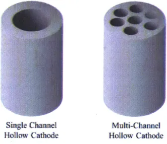
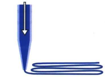
Figure 1: Single channel vs. multi-channel hollow cathode 9 Figure 2: Continuous direct ink writing schematic 10 Figure 3: Mayenite ceramic synthesis process 12
Figure 4: Hyrel 3D printer with Nordson pneumatic extruder 14
Figure 5: Water based alumina slurry prints 15
Figure 6: Acetone based alumina slurry prints 17 Figure 7: Acetone based alumina vs. mayenite slurry, same vol. composition 18 Figure 8: Unsuccessful print of acetone-based mayenite slurry 19 Figure 9: Explosion of acetone-based mayenite slurry 19 Figure 10: Best obtained extrusion of acetone-based mayenite slurry 20
1. Introduction
Additive manufacturing has long been a topic of great interest, due to its ability to shape novel materials into complex geometries that are difficult to achieve with standard, subtractive manufacturing techniques. The additive manufacturing of ceramics, in particular, is of significance, because the manufacturing of ceramic parts with traditional, subtractive manufacturing methods is more difficult than in other materials, and additive manufacturing could open up great geometric flexibility for ceramics [1]. In recent times, many different types of ceramics have been successfully 3D printed through an additive process called direct ink writing, where a ceramic slurry is extruded continuously as filaments on a moving stage, but there are many ceramics that have still not yet been printed with this method. Thus, the direct ink writing process of a ceramic called mayenite was examined in an effort to create complex geometries out of a derivative material of mayenite, mayenite electride.
Mayenite electride has recently been a material of high interest, as it is the first electride demonstrated to be stable at room temperature, and because it has a very low work function and great ability release electrons [2]. The motivation behind additively manufacturing mayenite electride lies in these unique properties, which could lead to potential applications in the manufacturing of specialized cathode arcs with complex geometries, in order to increase the efficiency of these cathodes [3].
So far, no literature has shown work on the direct ink writing of neither mayenite
electride nor the precursor ceramic of mayenite. However there has been extensive work on the direct ink writing of many other ceramics [4]. This past work was essential to helping create a baseline formulation for the mayenite direct ink writing slurry. There has also been work done
on the synthesis of mayenite and of mayenite electride [5], which was also essential for the synthesis of these chemicals in this work and for the creation of an additive manufacturing process.
And thus, in an effort to move towards being able to manufacture mayenite electride in complex geometries, the composition of mayenite slurries for the purpose of direct ink write printing was studied. Different solvent and binder combinations were tested with the mayenite, as well as different volume ratios of the different components of the slurries. These slurry compositions were also first test run with a more readily available ceramic, alumina as an initial gauge of printability, and then later tested with mayenite.
2. Background
2.1 Mayenite Electride: Low Work Function Ceramic
Mayenite (12CaO - 7A203 or Cl2A7), in its electride form has shown to have many
unique and promising properties, including being the first room-temperature stable electride to
be demonstrated [2]. Mayenite electride has a lattice structure, that cages in electrons, allowing
for it to become a conductive material. This structure is what gives mayenite electride some of its most promising properties. One of these properties includes its low work function, as the electrons that are trapped inside the cage-like lattice structure of mayenite are easily emitted from the material. One potential application for a material with such a low work function could be in hollow cathodes of electric propulsion thrusters [6]. The work function is a critical property to the efficiency of the cathode as it determines the temperature at which the cathode operates at, and thus the power needed to maintain such a temperature [6]. Thus, a material such as mayenite electride would be excellent to use as the cathode. In fact, a hollow cathode with a
mayenite insert was tested by Rand and colleagues, and was found that it operated at close to the
state of the art, with a few issues with the formation of a contamination layer [6]. However, the
team maintains that mayenite still stands as a promising material for these cathodes, with some
further development.Furthermore, other recent work on these propulsion thruster cathodes has suggested that
more complex geometries would improve overall performance of these cathodes. These more
complex geometries are known as "multichannel" cathodes, which increases efficiency of the
cathode by having gas flow through the many different, smaller holes (rather than one single
hole, as in the case of the standard hollow single channel cathods), which reduces power
dissipation [3]. Delcroix and colleagues, who were the first to study these types of multichannel
cathodes, also predict that this new geometry will increase lifespan of the cathode [3]. More
recently, experiments were done on a multichannel hollow cathodes made of tungsten, and the
experiments confirmed that the multichannel cathode operated at lower cathode voltage and
lower temperature than a single channel hollow cathode, and can conduct higher currents than
both a single channel hollow cathode and a solid cathode [7]. Thus, it would be ideal if a novel
material like mayenite electride, with its low work function, could be manufactured in the more
complex shape that is the multichannel hollow cathode. In order to do this, advanced
Single Channel
Multi-Chaninel
Hollow Cathode Hollow Cathode
Figure 1: The geometry of a single channel hollow cathode and a multi-channel hollow cathode shown above.
There are many different ways that mayenite electride is formed, including single crystal
and thin film growth [2], but one of the most promising and simple methods is heating of the
precursor ceramic, mayenite, in a reducing atmosphere
[5].
By utilizing this method of mayenite
electride production, complex geometries of mayenite electride can be created by first using an
additive manufacturing technique (direct ink writing) on the ceramic powder form of mayenite,
then taking that mayenite printed part and heating it under a reducing atmosphere in order to
create part made of mayenite electride, with a complex geometry. In an effort to pursue this, the
direct ink writing of mayenite was explored.
2.2 Direct Ink Writing
Generally speaking, "direct ink writing" refers to an additive manufacturing process that
utilizes a moving computer controlled stage, onto which material is deposited onto, usually in
layers, to create a 3D structure [8]. There are many forms of direct ink writing, many of which
can be categorized into two basic categories: droplet-based printing and continuous (or "filament") printing [4]. For this project, a continuous, extrusion-based printing method was utilized, in which the "ink" was deposited into a syringe with a nozzle that was attached to an
air-pressure dispensing system, as shown in Figure 2. The pressurized air would cause the ink to extrude out of the syringe, and create continuous filaments as the controlled stage translated.
Figure 2: A schematic describing the process of direct-ink writing used in this work (continuous and extrusion based).
There are also many different types of ink formulations that can be used with direct ink writing in general, and also with continuous printing specifically [8]. A few examples of these inks are shear thinning colloidal suspensions/gels, polymer melts, and waxes [1]. For the purposes of this project, a shear-thinning colloidal ink, or ceramic slurry, was utilized. Oftentimes, these slurries are characterized by having a high loading (of around 40-55% by volume) of the ceramic particles [9]. In addition to the ceramic powder, the ceramic slurries also usually contain a solvent, a binder, and dispersant [10]. The solvent is used as the liquid that holds together all the colloidal particles and other elements of the mixture, and is often
evaporated out in systems such as the one used. Dispersant, as the name may suggest, is used to disperse the ceramic particles from each other, and keep them from clumping together within the slurry [10]. Such agglomerates of ceramic powder can detract from printing ability as they can occasionally clog up the nozzle and prevent the slurry from extruding [9]. Next, the binder is used to bind together the ceramic particles together, and can increase green strength and
flexibility of ceramic part [10]. Clearly, the composition of the ceramic slurry used in the direct ink writing process is crucial to the printing ability and the characteristics of the final printed part. Subsequently, in order to facilitate the additive manufacturing of mayenite electride, the composition of the printed slurry must be extensively studied.
3. Methods
3.1 Ceramic Synthesis
And so, the first step in additively manufacturing mayenite was in synthesizing mayenite. In order to synthesize mayenite, calcium carbonate powder and aluminum oxide powder were added together into an alumina high energy ball mill jar. The two powders were ball milled together for six hours using a ball mill, and the resulting powder was then scraped out of the ball mill jar. This composite powder was pressed into 3 discs of about 5 grams each, each of which were massed prior to being placed in platinum crucibles. The three platinum crucibles were placed into an alumina combustion boat, which was then inserted into a tube furnace. The samples were heated to a temperature of 1325 degrees Celsius over a time period of 163 minutes (2 hours and 43 minutes), then held at a constant temperature of 1325 degrees Celsius for 12 hours, and then finally brought back to a temperature of 25 degrees Celsius over a time of 163 minutes (2 hours and 43 minutes). The three different discs were then massed in order to make
sure the post-furnace mass was less than the original mass, to check that the sintering process
had occurred. Then, these discs were taken and crushed into smaller bits initially using a mortar
and pestle, then further in the ball mill in a zirconia jar. Below, in Figure 3, is a schematic
describing this process and the process to take the mayenite.
PAY^* kw"uWM Sm'k PmrwwOfqi
Figure 3: Process of ceramic synthesis for mayenite.
3.2 Slurry Making Process
The process for creating the slurry varied depending on the exact type of slurry that was
being created. As described in the prior section, the process of synthesizing powders was not a
trivial one, and took a minimum of about three days to create around 15 grams of the ceramic.
Due to this restriction, alumina (aluminum oxide) powder was used initially to test different
slurry compositions and how their subsequent extrusion. Alumina was used as the "test" ceramic
because it was already commercially sold as a powder, was already being used in the synthesis of
the mayenite, and has been widely studied in the literature as a candidate for direct write
extrusion printing. Usually, before testing any potential slurry composition with the mayenite, a
"practice" slurry was made with the alumina, using similar volume ratios, in order to get a gauge
for the viability of the slurry for printing.
The process involved in creating a slurry varied with the slurry composition. If
dispersant was being used in a slurry composition, the process involved first combining the
dispersant, ceramic powder, and solution together into a jar and mixing (mixing time dependent on mixing method). Then binder is then added to the jar, and the mixture was again mixed. If dispersant was not being used in a particular slurry composition, then the ceramic powder, binder, and solution were added into the jar all at once, and the mixture was then mixed.
As mentioned, different mixing methods were used with different types of slurry compositions. The first, milling, was to put alumina milling media inside the jar that held the slurry, and place the jar so that it would roll continuously in a rock tumbler, repurposed as a rolling mill, overnight. The slurry was separated from the alumina milling media after mixing with a disposable, 190 micron TCP Global filter. Other mixing methods included using a metal spatula and mixing by hand for a few minutes, or using a Lab Digital overhead stirrer, to mix more vigorously for a few minutes. Once the mixing process was finished, and the slurry was ideally homogeneous, then the slurry was ready for the printing process.
3.3 Extrusion Printing
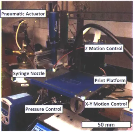
For printing, the slurry was placed inside of a Nordson EFD 3cc Optimum Syringe Barrel, with a luer-lock nozzle screwed in at the end. The different nozzles that were used were mainly 0.01" and 0.063" in diameter. At the opposite end of the syringe (the side without the nozzle), a Nordson EFD cartridge piston was placed so that pressure could be applied to the ink for extrusion. This whole syringe combination was then placed inside a Nordson HP3cc High Pressure Dispensing Tool, which was mounted on the printed itself. The printer itself that was used was the Hyrel3D Engine HR, and the pressure was supplied from an EFD Ultra 2400 dispensing workstation. The printer's stage was controlled by the software program Repetrel, a proprietary software from Hyrel3D, to which G-code commands were uploaded to in order to control the printing. Through this setup, the different slurry compositions were able to be tested
for their printability and viability for direct ink writing. Below, Figure 4 shows the setup of the
3D printing bed.
Pneum at Actuator
sringe
NozzlePrint Platform
X-Y Motion Conitrol
Pressure ControlK
50 MM
Figure 4: Hyrel machine with Nordson pneumatic extrusion.
4. Results: Slurry Compositions
4.1 Initial Tests: Water Based Alumina
As mentioned, the first slurry composition tests were done with alumina. These initial tests used deionized water as the solvent, again, as it was readily available, had a relatively high boiling point (and subsequently did not evaporate too much during slurry making), and was non-toxic. Additionally, polyvinylpyrrolidone was added as the binder, and an ammonium
used to thoroughly disperse alumina particles and mix in binder. Mechanical mixing was also
tested for this slurry, in order to save slurry creation time, but was found to be unsuccessful.
And ultimately, it was found that a starting point of 40% vol. ceramic powder was a good
starting point to start testing on mayenite.
Figure 5: Water-based alumina slurry, printed with a 40% vol. loading of alumina.
4.2 Water Based Mayenite
The next logical slurry to test was one of the same volume ratios as above, with deionized
water as solution, polyvinylpyrrolidone as the binder, ammonium polyacrylate solution (in
water) as the dispersant, but with the synthesized mayenite powder as the ceramic powder. The
same process as described above for this slurry (two days of mixing, with the rock tumbler).
However, it was found during the initial addition of the mayenite, dispersant, and deionized
water into the jar, that the three chemicals together were producing heat. Furthermore, the next
day, after mixing overnight, the mixture had turned into a completely rock-like structure,
nowhere near a slurry in viscosity. After looking further into the literature describing mayenite,
it was found that it is actually used in the process of making Portland cement, due to its rapid hardening ability and hydration reaction when mixed with water [11]. Thus, a different solvent needed to be used in order to effectively print with mayenite.
4.3 Secondary Tests: Acetone Based Alumina
The solvent that was tested was acetone, as it does not react with mayenite as water does, with cellulose acetate as the binder. Dispersant was not used with the acetone/cellulose acetate slurry mixtures, as the literature reporting the direct ink writing with this solvent and binder did not use any particular dispersant (although this may have been due to their lack of ceramic powder loading in inks printed) [12], and thus the decision to test the slurry without dispersant was made. Similar to the water based slurries, the acetone based slurries were again first tested with alumina.
A big difference in the process for these acetone based slurries was in the lower boiling
point of acetone, meaning that the acetone would quickly evaporate during the assembly or mixing of the slurry. And thus, when attempting to utilize the rock tumbler and alumina mixing media for the slurry, much acetone was lost during the straining process of the slurry, making it
impossible to know what the final, extruded composition was. To combat this, hand mixing was utilized, to get rid of this straining step. In addition, when adding acetone, first the jar with the alumina, binder, and mixing spatula was placed on a scale, which was then tared. Then, the appropriate amount of acetone was added, the slurry was mixed, and then placed back on the scale, to see how much acetone was lost during mixing, and more acetone was added
Ultimately, it was found that a composition of 40% vol. alumina,
2.5%
vol. binder, and
57.5%
vol. acetone was adequate for printing with a nozzle size of 0.01" in diameter, as shown
in Figure 6 with the print tests.
Figure 6: Acetone-based alumina slurry, printed with a 40% vol. loading of alumina.
4.4 Acetone Based Mayenite
With the printing achieved with the alumina-acetone slurry, the next step was to print the acetone based slurry with mayenite. The volume ratios of this slurry and methodology of creating this slurry was initially the same as described above, for the acetone based alumina slurry. However, one problem that was encountered was that mayenite seemed to act differently as a colloidal particle when compared to alumina in acetone, as a slurry with mayenite had a qualitatively different viscosity when compared to a slurry with alumina of the same volume ratio. This difference can be seen below in Figure 7.
Figure 7: (a) Acetone based alumina slurry, with a vol. 40% alumina powder, (b) Acetone based mayenite slurry, with a vol. 40% of mayenite powder. The mayenite slurry is less viscous (and is shown dripping) despite the similar volume loading of ceramic powder.
Due to this difference, it was inferred that the volume ratios had to be tweaked for the mayenite slurry in order to create a slurry that would properly print. However, before new volume ratios for the acetone based mayenite slurry could be properly investigated, a different
problem arose in the printing. During attempted printing of the mayenite slurry, no matter how
high pressure was (even at the maximum pressure of 70 psi on the EFD Ultra 2400 dispensing workstation), the slurry would not seemingly come out unless the nozzle opening was initially "cleared" with a needle or a smaller nozzle (meaning a smaller nozzle head was jammed up the nozzle head that was being used). And, even when the printing nozzle was "cleared," extrusion
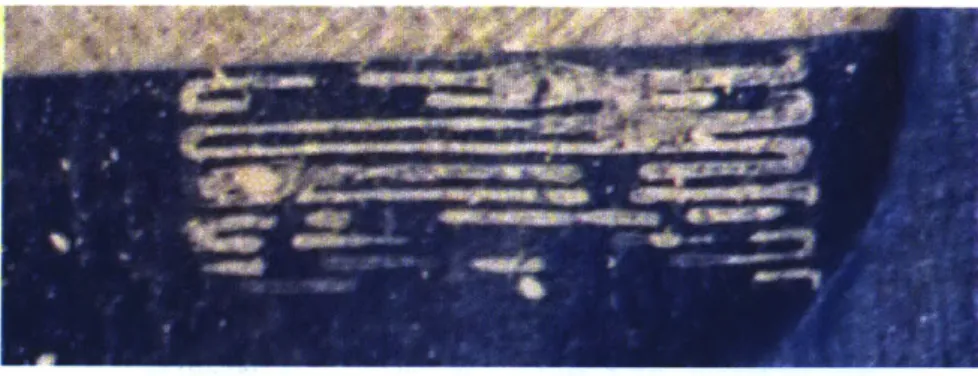
would usually only happen very minimally. Below, in Figure 8, we can see very minimal
Figure 8: Acetone-based mayenite slurry, but the slurry is barely able to be printed, even
at maximum pressure.
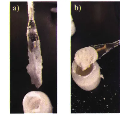
At one point, however, with the same slurry. that was printed the lines shown in Figure 8, and at the same pressure, a good portion of the ink suddenly exploded out, as shown in Figure 9.
However, all the ink did not explode out of the nozzle, as shown by the half full barrel of the
syringe in Figure 9, next to the explosion that had happened briefly prior.
Figure 9: Explosion of acetone-based mayenite slurry due to an over-pressurized syringe. However, something clogged the nozzle during the explosion, preventing all of the ink from exploding out all at once, as shown by the half-full barrel of ink.
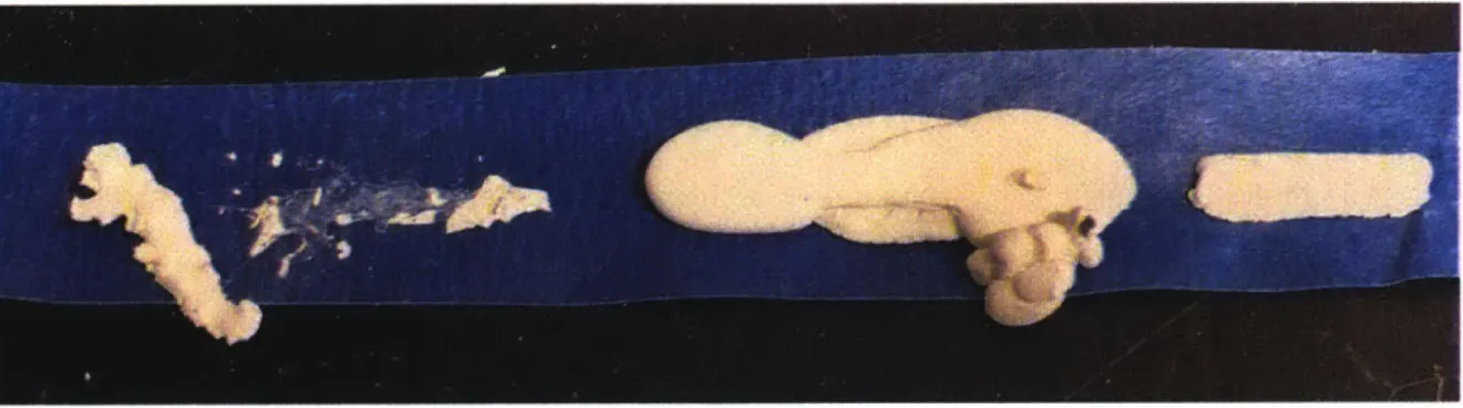
And finally, there was one semi-successful extrusion of the acetone-based mayenite
slurry, but only with a nozzle diameter that was much bigger (0.063" diameter) than nozzle
diameters that had been used for the acetone based alumina slurries (0.01" diameter). Below, in
Figure 10, the results of this enlarged nozzle extrusion can be seen.
Figure 10: The best attempts that were made to print an acetone-based mayenite slurry, done with a significantly larger nozzle size.
5.
Conclusions
Although mayenite was not completely successfully printed, from this work it can be
concluded that a better dispersal system for the mayenite powder needs to be pursued for the printing of mayenite to be successful. This was concluded through all of the mishaps in
attempting to print the mayenite. The mayenite often would have trouble extruding through the nozzle, seemingly because the nozzle would become clogged up with an agglomerate of mayenite. It was decided that the agglomerates of mayenite could have had a two potential sources: the acetone or the mayenite powder.
The reason acetone was a potential source of the inability of the mayenite slurry to print
ruled out because the acetone had not caused this sort of problem with the alumina, so it did not make sense that a similar problem was happening with the mayenite.
This meant that the source of the slurry's problems was in the mayenite powder itself. This conclusion would corroborate the result shown in Figure 9 above, in which the mayenite slurry suddenly explodes out of the nozzle due to being over-pressurized, but not all of the slurry leaves the nozzle during this explosive incident. Since not all of the slurry leaves the nozzle, it must mean that as the slurry was exploding out of the nozzle, some larger chunk of mayenite most likely clogged the nozzle and prevented the extrusion/explosion of the rest of the ink. This indicates that there are large clumps in the mayenite mixture that are not being formed by the evaporation of acetone, as the time scale of the explosion was too short for acetone to have evaporated and already created a clump. It would also explain how in Figure 8, the mayenite slurry barely was able to print at maximum pressure, but in Figure 9, the mayenite slurry exploded out (until it was clogged, again). This is because the nozzle was also most likely similarly clogged in Figure 8, where it barely printed.
This conclusion also corroborates the result in Figure 10, in which the best possible extrusion was done with a larger nozzle size. With a larger nozzle size, potentially more of the clumps of mayenite were able to pass through, allowing for a more successful extrusion.
And finally, this conclusion also potentially explains the large variation in slurry viscosity in alumina slurries and mayenite slurries that still have the same volume loading of ceramic, as shown in Figure 7. If the difference in apparent viscosity was due to the fact that the mayenite was clumping and not dispersing as well as the alumina powder, it would make sense that the mayenite slurry appeared less viscous. This is because rather than dispersing throughout the acetone and making the slurry more viscous by acting as a colloidal particle, the mayenite
was simply clumping together. In contrast, more of the alumina particles more readily dispersed throughout the acetone and acted as colloidal particles, making the acetone slurry appear more viscous.
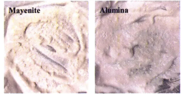
These large clumps are probably due to a lower degree of dispersion of the mayenite powder in the acetone when compared to the alumina powder. A quick comparison between a mayenite-acetone mixture and an alumina-acetone mixture, shown below in Figure 11, seems to confirm this, as the mayenite mixture has significantly larger chunks, when compared to the alumina mixture.
Mayenite
Figure 11: A qualitative comparison between the clumps of ceramic in a mixture of mayenite and acetone (left) and alumina and acetone (right).
Thus, it can be concluded from this work that synthesized mayenite does not disperse as well as the commercial alumina. In order to combat this, a dispersant could be added, the
mixture could be mixed more vigorously or for a longer time period, or the particle size of the
synthesized mayenite could try to be decreased. In order to determine the best route to increase dispersion, further work must be done.
6. Future Work
The big takeaway from this work was that much further work will be needed to be done in order to fully realize the direct ink printing of mayenite electride. First, more intensive powder characterization must be done on the mayenite, including an investigation on how it interacts with acetone (or any other potential solvent for the slurry) as a colloidal particle, in order to determine how to increase the dispersion of the mayenite in acetone. In tandem, more work could be done in identifying a potential dispersant that could work for the cellulose acetone based mayenite slurry, testing methods to decrease particle size of the synthesized mayenite, and finding new methods to better mix the slurries. These would all decrease the clumping the mayenite in the slurry, which was concluded to be the main problem thus far. Furthermore, an investigation on whether or not the acetone and cellulose acetate is the best solvent and binder combination for the printing of mayenite should be pursued. Another potential option is using isopropyl alcohol (IPA) as the solvent and polyvinyl butyral as binder, which could be easier as IPA has a higher boiling point when compared to acetone. Then, once the slurry composition is finalized, and the chemicals for the binder, dispersant, and solvent are chosen, an investigation on the mayenite slurry's rheology and its effects on printability would be a solid next milestone. And finally, in order to bring this work to application, the printing of the multichannel hollow cathode tubes with the DIW mayenite and the testing of these tubes must be pursued.
7.
Bibliography
[1] Eckel, Z. C., Zhou, C., Martin, J. H., Jacobsen, A. J., Carter, W. B., and Schaedler, T. A., 2016, "Additive Manufacturing of Polymer-Derived Ceramics," Science, 351(6268), pp.
58-62.
[2] Kim, S. W., and Hosono, H., 2012, "Synthesis and Properties of 12CaO 7A1203 Electride: Review of Single Crystal and Thin Film Growth," Philos. Mag., 92(19-21), pp. 2596-2628.
[3] Delcroix, J. L., Minoo, H., and Trindade, A. R., 1969, "Gas Fed Multichannel Hollow
Cathode Arcs," Rev. Sci. Instrum., 40(12), pp. 1555-1562.
[4] Lewis, J. A., Smay, J. E., Stuecker, J., and Cesarano, J., 2006, "Direct Ink Writing of Three-Dimensional Ceramic Structures," J. Am. Ceram. Soc., 89(12), pp. 3599-3609.
[5] Kim, S.-W., Hayashi, K., Hirano, M., Hosono, H., and Tanaka, I., 2006, "Electron Carrier
Generation in a Refractory Oxide 12CaO 7Al203 by Heating in Reducing Atmosphere: Conversion from an Insulator to a Persistent Conductor," J. Am. Ceram. Soc., 89(10), pp. 3294-3298.
[6] Rand, L. P., Waggoner, R. M., and Williams, J. D., 2011, "Hollow Cathode With Low Work
Function Electride Insert," ASME, pp. 317-323.
[7] Cassady, L. D., "LITHIUM-FED ARC MULTICHANNEL AND SINGLE-CHANNEL
HOLLOW CATHODE: EXPERIMENT AND THEORY," p. 273.
[8] Lewis, J. A., 2006, "Direct Ink Writing of 3D Functional Materials," Adv. Funct. Mater.,
16(17), pp. 2193-2204.
[9] Lewis, J. A., 2002, "Direct-Write Assembly of Ceramics from Colloidal Inks," Curr. Opin.
Solid State Mater. Sci., 6(3), pp. 245-250.
[10] "Ceramic Slurry -an Overview I ScienceDirect Topics" [Online]. Available:
https://www.sciencedirect.com/topics/engineering/ceramic-slurry. [Accessed: 06-May-2019]. [11] Zhen, G., Lu, X., Cheng, X., Chen, H., Yan, X., and Zhao, Y., 2012, "Hydration Process
of the Aluminate 12CaO-7AI203-Assisted Portland Cement-Based
Solidification/Stabilization of Sewage Sludge," Constr. Build. Mater., 30, pp. 675-681.
[12] Pattinson, S. W., and Hart, A. J., 2017, "Additive Manufacturing of Cellulosic Materials with Robust Mechanics and Antimicrobial Functionality," Adv. Mater. Technol., 2(4), p.
1600084.
[13] Austin, L. G., Yekeler, M., Dumm, T. F., and Hogg, R., 1990, "The Kinetics and Shape
Factors of Ultrafine Dry Grinding in a Laboratory Tumbling Ball Mill," Part. Part. Syst.