Publisher’s version / Version de l'éditeur:
IEEE Transactions on Biomedical Engineering, 60, 4, pp. 1013-1022, 2012-11-29
READ THESE TERMS AND CONDITIONS CAREFULLY BEFORE USING THIS WEBSITE. https://nrc-publications.canada.ca/eng/copyright
Vous avez des questions? Nous pouvons vous aider. Pour communiquer directement avec un auteur, consultez la première page de la revue dans laquelle son article a été publié afin de trouver ses coordonnées. Si vous n’arrivez pas à les repérer, communiquez avec nous à [email protected].
Questions? Contact the NRC Publications Archive team at
[email protected]. If you wish to email the authors directly, please see the first page of the publication for their contact information.
NRC Publications Archive
Archives des publications du CNRC
This publication could be one of several versions: author’s original, accepted manuscript or the publisher’s version. / La version de cette publication peut être l’une des suivantes : la version prépublication de l’auteur, la version acceptée du manuscrit ou la version de l’éditeur.
For the publisher’s version, please access the DOI link below./ Pour consulter la version de l’éditeur, utilisez le lien DOI ci-dessous.
https://doi.org/10.1109/TBME.2012.2230326
Access and use of this website and the material on it are subject to the Terms and Conditions set forth at
Real-time blood circulation and bleeding model for surgical training
Boisvert, Jonathan; Poirier, Guillaume; Borgeat, Louis; Godin, Guy
https://publications-cnrc.canada.ca/fra/droits
L’accès à ce site Web et l’utilisation de son contenu sont assujettis aux conditions présentées dans le site LISEZ CES CONDITIONS ATTENTIVEMENT AVANT D’UTILISER CE SITE WEB.
NRC Publications Record / Notice d'Archives des publications de CNRC:
https://nrc-publications.canada.ca/eng/view/object/?id=3632eb13-17ad-42fd-9e90-1e9892e0b07c https://publications-cnrc.canada.ca/fra/voir/objet/?id=3632eb13-17ad-42fd-9e90-1e9892e0b07c
Real-time Blood Circulation and Bleeding Model
for Surgical Training
Jonathan Boisvert, Guillaume Poirier, Louis Borgeat and Guy Godin
Abstract— Intra-operative management of bleeding is a critical skill all surgeons must possess. It is however very challenging to create a safe and realistic learning environment for its acquisition. In this paper, we propose a simple and efficient approach to integrate blood circulation to computerized surgical simulation systems and allow for real-time processing of punctures, ruptures, and cauterization of blood vessels. Blood pressures and flows are calculated using a system of ordinary differential equations, which can be simulated very efficiently. The equation system itself is constructed using a graph of the vessels’ connectivity extracted from magnetic resonance angiograms (MRA) and completed with virtual vessels deduced from the principle of minimum work. Real-time performances of the method are assessed and results are demonstrated on ten patients who underwent an MRA before removal of a brain tumour.
I. INTRODUCTION
Training new surgeons efficiently in realistic conditions without compromising patient safety has always been chal-lenging. Surgical interns can acquire a wealth of knowledge in the classroom, but practical education is nonetheless necessary. Certain skills can be acquired by practicing on manikins or cadavers where mistakes can be committed without doing harm to a patient and where trainees can spend as much time as they need to perfect their techniques with minimal supervision. However, static manikins and cadavers don’t breathe, bleed, or present sudden complications.
Similar problems arise when introducing new surgical equipment such as medical robots. Those new tools often come with a significant learning curve. New manual skills must be acquired and mastered in realistic conditions before one can operate a medical robot safely and efficiently. Unfortunately, traditional mentoring is difficult since the surgeon and his/her first assistant/resident may not even be in the same room when performing robot-assisted surgery (e.g. [1]).
Computerized surgical simulators have emerged as a solu-tion to alleviate some of the difficulties previously mensolu-tioned. Suitable tool-tissue interaction models [2] coupled to haptic devices allow trainees to feel how much force needs to be applied for different manipulations and to learn hand-eye coordination for specialized techniques (e.g. microsurgery, robot-assisted surgery, or endoscopy). Rare variations of the anatomy can be generated at will and dynamic elements such as breathing, heart beat, and ambient sounds can easily be integrated for enhanced realism.
One area where computerized surgical simulators can have a major impact is surgical hemostasis. The presence of blood or
Corresponding author’s email address: [email protected]. Authors are affiliated with the National Research Council of Canada.
hemorrhages in the operating field is a fundamental challenge in surgery since the visibility of key anatomical structures is impeded and stopping bleeding is a time-critical task. A successful model of surgical hemostasis should include elements such as blood circulation in the vessels, the presence of hemorrhages, and the ability to cauterize.
Significant efforts have been targeted at fluid simulation and visualization of blood in the operating field. Simple particle systems were initially used to approximate blood presence in the scene [3]. Smoothed particle hydrodynamics was then con-sidered since it allowed to integrate fluid dynamics to particle systems [4], [5]. Three-dimensional and two-dimensional grid-based approaches to fluid simulation were also investigated [6], [7]. Finally, a layered height field approach was recently proposed [8].
These approaches consider hemorrhages as local phenom-ena and blood circulation in the body is not taken into consid-eration. However, vascular anatomy often plays an important role in surgical planning as well as in the execution of the surgery. For example, finding and cauterizing the blood vessels feeding a tumour before removing it will generally reduce blood loss for the patient. Important arteries can also be located near the surgical field and additional care must then be taken to avoid major hemorrhages which could have debilitating consequences for the patient. In other words, simulating blood circulation in real time in a vascular model is extremely beneficial for learning and practicing surgical hemostasis.
There are multiple strategies to simulate blood flow in the vascular system. One can elect to perform fluid simulation on a three-dimensional mesh[9], [10], [11], [12]. This approach is very flexible, but it has the drawback of being computationally expensive. Thus, it is applicable only to small sections of the vascular system. For the same reason, it is also difficult to apply this strategy in real time with advanced 3D visualization and soft-tissue simulation running in parallel as part of a larger surgical simulation system.
One way to reduce tremendously the computational require-ments of the simulation is to consider blood vessels as being a network of tubular structures where each section has a constant circular cross-section. In such circumstances, one could use the Hagen-Poiseuille equation to describe the relationship between pressure drops and volumetric flow rate in the blood vessel. This idea was used by Wu et al. [13] in the context of angiography simulation. Tuchschmid et al. [14] used the same idea to study absorption of distention liquids by the vascular system during hysteroscopy or transurethral resection of the prostate.
One of the limitations of previous approaches is the rel-atively restricted set of operations that could be performed in real time. The creation of new hemorrhages, cauterization, and operations such as vessel subdivision were not previously included. Thus, we propose in sections II and III a blood circulation model which allows hemorrhages and dynamic manipulations.
Furthermore, previous approaches assumed complete or nearly complete vascular data. Clinical imaging protocols usually only perform angiography near the operating theatre with a finite resolution. As a result, small vessels, vessels that cross image boundaries, and vessels carrying blood at a lower velocity (e.g. veins) are often absent from vascular models segmented from angiographic images. We thus propose in section IV an approach to deal with incomplete arterial models.
The integration of such a model to a real surgical simulation system also comes with important challenges. Section V there-fore details how the proposed scheme was integrated within the NeuroTouch surgical simulation system [15] (http:// www.neurotouch.ca), which is a complete simulator that provides soft-tissue simulation, haptic feedback, advanced vi-sualization techniques, and surface fluid simulation. Section VI then presents experimental results as well as demonstrations of the proposed method and section VII discusses advantages, drawbacks and future work. Finally, section VIII offers a brief summary of the presented material.
II. DIFFERENTIALMODEL FORBLOODCIRCULATION
The differential model used to simulate blood circulation for surgical training includes three components. First, the inter-connected vessels themselves carry blood through the vascular system. Second, the hemorrhages allow blood to escape from vessels and should be successfully managed during a surgery. Finally, the pressure sources supply the energy necessary to overcome friction and force the blood circulation. The pressure and flow in those elements are governed by different equations, which when combined together form the differential model that must be solved during simulation.
A. Blood Vessels
The relationship between the hydrostatic pressure drop and volumetric flow rate in blood vessels is often approximated by the Hagen-Poiseuille law (see [14], [13] for example), which is summarized by the following equation:
∆p = 8µL
πr4q, (1)
whereq is the volumetric flow rate, r the radius of the vessel, µ the blood viscosity, L the vessel length and ∆p the pressure drop in the vessel.
This approximation is based on a steady, laminar, axisym-metric, and fully-developed flow in a cylindrical container. Small vessels generally comply with those assumptions quite well. Larger vessels may not necessarily do so and it is often necessary to add terms to the Hagen-Poiseuille law to better model the flow. Olufsen et al. [16] demonstrated that
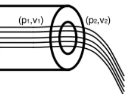
(p1,v1) (p2,v2)
Fig. 1. Simple hemorrhage located at the end of a blood vessel.
for vessels with a radius from 0.2cm to 0.5cm an additional term that describes the blood inertia would be beneficial. The relationship between pressure and flow then becomes:
8µL β2 1νπr2 dq dt + 8µL πr4q = ∆p, (2)
where ν is the kinematic viscosity of blood and β1 the first
root of the Bessel functionJ0(βn) = 0.
Since we are primarily interested in neuro-surgeries, we were not interested in blood vessels larger than0.5cm. Other approximations can be derived from the Navier-Stokes equa-tions for larger blood vessels. Higher-order differential terms would then be necessary to properly describe the relationship between flow and pressure.
B. Hemorrhages
In order to integrate hemorrhages in our simulation, we must establish a relationship between pressure and flow. Moreover, in order to obtain predictable real-time performances, we must also limit ourselves to a linear relationship. Fortunately, this can be done with a few assumptions.
Let us consider a blood vessel which ends with a small circular hole (see Fig. 1). In such case, Bernoulli’s equation for incompressible fluids gives us [17]:
z2+ p2 ρg+ v2 2 2g+ hf = z1+ p1 ρg + v2 1 2g (3) where v1,p1,z1 and v2,p2,z2 are respectively the velocities,
pressures, and elevation on both sides of the hole, and hf is
the head loss (which corresponds to the energy dissipation due to friction).
Conservation of mass implies thatπr2
1v1= πr22v2(r1being
the radius of the blood vessel and r2 the radius of the hole).
Now, assuming atmospheric pressure atp2(p2= 0), no change
in elevation (z1= z2), and expanding the head loss using the
Darcy–Weisbach equation (hf = fDLv 2 2 2g = K v2 2 2g) [17], we obtain : v2(p1) = v u u t 2p1 ρ⇣K + 1 −r42 r4 1 ⌘ . (4)
The constantK allows to take into consideration how much energy is lost when the blood exits a blood vessel. The actual value depends on a large number of factors, such as the shape of the hemorrhage, the thickness of the vessel wall, its physical characteristics, and the Reynolds number of the flow. In practice, a rough approximation is sufficient since our goal is to qualitatively reproduce the effects of surgical
manipulations on hemorrhages and not to predict the amount of blood loss. For the case presented in Figure 1, we used K ≈ 1.5 which corresponds to a sudden constriction followed by a pipe exit [18]. In most cases, the hemorrhage will be perpendicular to the vessel’s tangent. In these cases, we used K ≈ 10, which corresponds to a tee fitting in a pipe system with laminar flow [17], [18].
In order to comply with the real-time constraints of our problem, we further simplify this relationship by linearizing it between the minimum pressure (p1 = 0) and the maximal
pressure (ps, which is the systolic pressure) experienced in the
brain vascular system. Equation 4 then becomes:
v2≈γp1, with: γ = v u u t 2 psρ ⇣ K + 1 −r42 r4 1 ⌘ . (5) C. Pressure Source
The vascular network needs an external pressure source or pump to force the blood through the vessels. Unlike many organs, the brain receives pressurized blood from multiple arteries, namely, the two vertebral arteries and two carotid arteries. Each of those entries is thus connected to a time-varying pressure source. The pressure profile used is a si-nusoidal rhythm between the systolic and diastolic pressures (respectivelypsandpd):
∆p(t) = (ps−pd)
2 sin(ωt) +
ps+ pd
2 . (6)
However, nothing would prevent the use of a more elaborate windkessel model [19] or even the use of functionals that mimic different types of arrhythmia.
D. Vascular System
The blood vessels, hemorrhages, and pressure sources are connected together and the topology of the resulting graph gives rise to a system of differential equations. A first set of equations is found by balancing the flow entering and leaving all nodes except the sink, which is an arbitrarily chosen node that has atmospheric pressure (p = 0). This can be compactly expressed as:
Aq = 0, (7)
whereA is the node-edge adjacency matrix with constituting elements defined as:
Ai,j = 8 > < > :
1 if edgej leaves nodei
−1 if edge
j enters nodei
0 otherwise
. (8)
The second and final set of equations is given by the characteristic equations of constituting elements (Equations 2, 5, and 6). The complete system of equations for the vascular system can thus be expressed as:
✓ 0 A 0 B C AT ◆ 2 4 q0 q p 3 5= 0 K(t) 1 (9)
whereB, C and K are deduced from Equations 2, 5, and 6. In order to simulate this system, one must discretize. Thus, let us consider the following:
q0≈ qn
∆ + f
−(q
n−1, qn−2, . . . , qn−N), (10)
where qn designates the flows for the nth time step, ∆ is
the time elapsed between two consecutive time steps, andf−
completes any explicit finite difference scheme to approximate the first derivative.
After reorganization,qn andpn (respectively the flows and
pressures for thenthtime step) are given by:
qn pn 1 = M−1 0 −Bf−+ K(t) 1 (11) with M = ✓ A 0 (B ∆+ C) A T ◆ .
Explicitly computing the inverse in Equation 11 is, of course, not the only possible strategy to solve the system. A direct solver that supports non-symmetric sparse matrices, such as UMFPACK [20], may also be a good choice. However, the inverse only has to be computed once if no changes are made to the structure of the vascular graph. Thus, for a graph with less than approximatively 2000 elements, Equation 11 results in less computational resources being consumed (see Figure 8). Furthermore, the number of instructions needed will not vary for a pre-defined problem size. These two properties are especially important since other demanding tasks need to be performed in real time (e.g. soft-tissue deformation, collision detection, haptic feedback computation).
III. REAL-TIMEUPDATES TO THEDIFFERENTIALMODEL
In the course of a simulation, user actions will cause changes in the equation system that describes the blood circulation. Recomputing the whole inverse matrix from Equa-tion 11 should, however, be avoided to maintain real-time performances. Fortunately, it is possible to reuse the current inverse matrix and to update it to take in account the user’s actions at a much lower computational cost.
A. New Hemorrhages
As a surgery progresses, blood vessels get damaged and bleeding occurs. The importance of the bleeding depends on the nature of the damage, but also on the blood pressure at the bleeding site. When a new hemorrhage appears, two modifications need to be performed to the system. First, an additional equation is needed to describe the relationship between the flow and pressure for the new hemorrhage. Then, the flow balancing equation of the originating node needs to be corrected to include the blood volume exiting the wound. Both operations can be performed by a single block-wise inversion operation which, after taking into account the sparse nature of the new matrix elements, is given by the following equation:
M0−1 = M ui −γuT j 1 1−1 =E F G H 1 with: (12)
E = M−1−(M−1)i(1 + γ(M−1)j i)−1γ(M−1)j F = −(M−1) i(1 + γ(M−1)ji)−1 G = (1 + γ(M−1)j i)−1γ(M−1)j H = (1 + γ(M−1)j i)−1,
where ui anduj are, respectively, the ith andjth column
of an identity matrix. A subscript after parenthesizes (e.g. (M−1)
i) refer to a specific column of a matrix while a
superscript refer to specific row (e.g.(M−1)j). Consequently,
the combination of both subscript and superscript refers to a given element of the matrix.
The new line inM0describes the pressure/flow relationship
of the new hemorrhagej that connects the node i with the sink and the new column modifies the flow balancing equation for node i.
B. Cauterization, Clamping and Ligature
In order to maintain hemostasis, it is often necessary to stop or reduce the flow of blood in vessels (either permanently or temporarily). A surgeon can clamp, ligature, or cauterize a vessel using an electrosurgical device to reduce its effective radius. Reducing the radius of a single vessel changes only one element in the matrixM (which describes the whole system). The difference between the new element and its former value is given by: (∆M )n+ii = 8µL π r−2−r0−2 ∆β2 1ν + r−4−r0−4 ! . Thus, updating the inverse M−1 can be performed by
applying a simplified Sherman-Morrison formula [21]: (M + ∆M )−1= M−1−(∆M ) n+i i (M−1)n+i(M−1) i 1 + (∆M )n+ii (M−1)i n+i (13) The above formula implies performing a single dyadic product ((M−1)
n+i(M−1)
i
), which is considerably faster than recomputing the inverse of the complete matrix.
C. Vessel Subdivision
Vessels can be quite long and operations such as cauteriza-tion usually apply only to a short subseccauteriza-tion. Thus, it may be necessary to subdivide the representation of a long vessel into shorter segments. This process is done in two steps.
First, the equations associated with the new segments, the new nodes and the new flows need to be integrated to the current description of the vascular system. This first step is done using a block-wise inversion. The new lines in the matrix M describe the characteristic equations of the new vessels and the new flow balancing equations of the new nodes. New columns of existing lines are used to complete existing flow balancing equations when needed.
The second step removes the old vessel from the flow balancing equations using the Sherman-Morrison formula. One must be careful to perform those two actions in order, otherwise the graph may become disconnected, thus leading to a singular M matrix.
IV. VASCULARNETWORKCOMPLETION
Patient-specific models extracted from medical images are, by nature, incomplete. Numerous reasons contribute to explain this phenomenon. For instance, vessels smaller than the image resolution are unlikely to be detected and modelled correctly. The image volume is finite and vessels cross image boundaries. Moreover, angiographic images are often based on the detec-tion of a moving liquid. The vessels will not be detected if the velocity of the liquid is not sufficient. Because blood travels faster in the arteries than in the veins, veins are often not visible in modalities such as time-of-flight magnetic resonance imaging (ToF-MRA). For all those reasons, it is necessary to complete vascular networks extracted from images.
We therefore need to add new virtual vessels at the end of each leaf in the graph in order to complete it before simulation. Those virtual vessels act as a substitute for the parts of the vascular network that are not visible on the original images. Both the length and the radius of those vessels can equivalently be adjusted to obtain physiologically realistic flows. We chose to adjust the length for numerical stability reasons. Thus, we set the radius of those vessels to be equal to the visible vessel they prolong. Then, we optimize the length of the virtual vessels so that the flows in the original vessels are physiologically realistic.
A simple yet powerful way to model realistic flows in arter-ies comes from the principle of minimum work as proposed by Murray [22]. In a few words, Murray postulated that the sum P of the power expenditures to circulate the blood through a vascular system Pq and the metabolic consumption of the
bloodPb should be naturally minimized.
It follows from Murray’s hypothesis that the optimal flow in a vessel is linked to the cube of its radius as demonstrated by the following equations:
P = Pq+ Pb= pq + bV = q2l8µ πr4 + blπr 2 , ∂P ∂r = 0 =⇒ ˜q = r 3π 4 s b µ (14)
where r is the vessel radius, µ the blood viscosity, and b = 1.93 10−6J/mm3/s is the metabolic cost of blood.
The length of the virtual vessels are therefore obtained by minimizing the difference between optimal flows as predicted by the principle of minimum work and the actual flow in the vessels. This can be formalized as follows:
minimize l 5 5q − ˜q5 5 subject to ✓A0 0 C0 A0T ◆ ✓q0 p0 ◆ =✓ 0 K0 ◆ l > 0 , (15)
whereA0,q0,p0,K0, andC0 are augmented versions ofA,q,p,
K, and C where the virtual vessels were added. After a few algebraic transformations, the problem becomes:
minimize l 6 6 6 6 6 6 6 6 6 6 γ −C−1 0 1T A0T7A0C0−1A0T8−1 A0C−1K 0 166 6 6 6 6 6 6 6 6 with γ = C−1K − ˜q C0=C 0 0 diag(πr8µl4) 1 subject to l > 0 , (16) which is a bounded non-linear problem that can be efficiently optimized using a non-linear optimizer such as L-BFGS-B [23].
V. INTEGRATION INTO ASURGICALSIMULATIONSYSTEM
Blood circulation is only one aspect of a surgical simulator. Such simulators are complex systems where numerous com-ponents must be integrated: soft-tissue deformation models, haptic devices feed-back, surface fluid simulation, surgical instrument simulation, photo-realistic computer graphics, etc. The integration of such a blood circulation model to the full system is therefore far from being trivial.
The work described in this paper was done within the con-text of the development of a complete patient-specific surgery simulation framework called NeuroTouch [15] (http:// www.neurotouch.ca). This framework specifically targets brain surgery and already incorporates a large number of software components necessary for convincing surgical sim-ulation. Moreover, this framework can be used for a wide range of procedures and adapted hardware configurations were developed. For instance, specific hardware platforms were created for craniotomy as well as endonasal procedures. While the integration solution proposed here is specifically adapted to the NeuroTouch framework, different solutions could certainly be implemented for other simulators.
In NeuroTouch, the high resolution visual appearance of soft-tissues is stored in a three-dimensional texture (which will be referred to as the visual texture). This texture is linked to the deformable polygonal models used for tissue simulation through an initial parameterization. Therefore, during simu-lation, there is no need to create new surface textures each time the mesh is deformed or a piece of tissue is removed using a surgical instrument. Corresponding areas of the 3D surface texture are simply mapped on the exposed tissue area, and will follow deformation of the coarser simulated mesh. For NeuroTouch, it is therefore possible to perform the visual integration of the blood vessels by pre-rasterizing them into this visual texture.
NeuroTouch already integrates advanced algorithms to sim-ulate in real time the behaviour of blood on the surface of a deformable mesh [8]. It was therefore necessary to connect the blood circulation model to the current blood simulation. Prior to the integration of the blood circulation model, information stored in the visual texture, combined with timing information relating to the last cauterization/cutting actions, were used to determine the amount of blood produced for a given surface fragment/pixel.
With a blood circulation model, the intensity of bleeding must be proportional to the flow in an hemorrhage located on a vessel at the corresponding location. That location depends on the current deformations. Thus, we used another three-dimensional texture to track the identity of the blood vessel and/or hemorrhage corresponding to a given location in the deformable mesh.
Due to the fact that the vascular structure only intersects a small proportion of voxels in a volumetric grid, it is clear that an array representation would waste a significant amount of memory due to the large texture size required to achieve satisfactory resolution. Thus instead of a conventional three-dimensional texture, an octree texture was implemented [24], [25], [26]. In typical cases, these textures had 5123 elements,
which means 512MB of uncompressed memory. The memory requirement would typically go down to about 1MB with the help of the octree texture. Once the vessel had been identified via the octree texture, then corresponding pressures and/or flows from hemorrhages could be retrieved to control the rate at which surface blood accumulates.
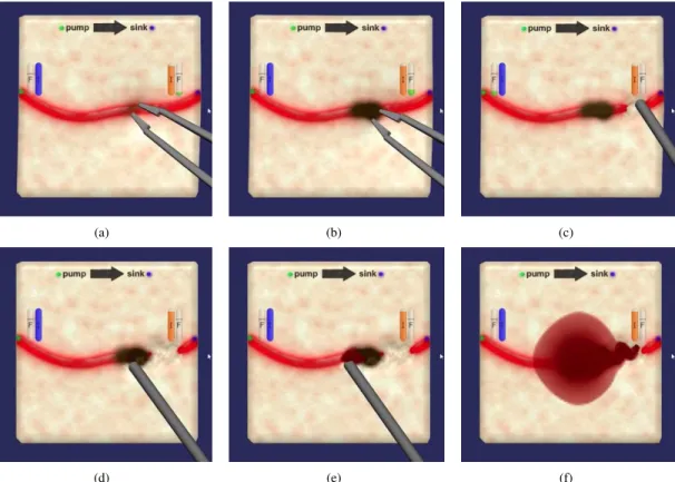
The behaviour of surgical instruments also had to be modified to reflect the modifications they could cause to the vascular model. The instruments were already governed by sophisticated models [27], [28]. We therefore only had to add certain actions to update the vascular model. The bipolar (instrument visible at Figure 2(a)) now reduces the internal radius of the vessel it touches and the suction device (visible at Figure 2(c)) now adds hemorrhages to the vascular model when the interior of a blood vessel is exposed.
Figure 2 presents an example of interaction where bleeding is modulated by the blood circulation model and where this model is modified because of the actions taken by the surgical instrument. Please note that a computer animation including a live video demonstrating those manipulations is available as supplementary material (link to the video). Figure 2(a) corresponds to the cauterization of a blood vessel with a bipolar tool. This manipulation results in the subdivision of the original vessel and the reduction of the internal diameter of one of the subdivided segments. Then (Figure 2(c)), a suction device is used on the downstream vessel. This manip-ulation results in very little bleeding as the upstream vessel was obstructed by the cauterization. However, damaging the upstream vessel (Figure 2(e)) results in a much more intense hemorrhage. Careful observation even reveals what looks like a wave propagating on top of the blood pool, which may be caused by the variation of arterial pressure during a cardiac cycle.
VI. EXPERIMENTS ANDRESULTS
The proposed method was sucessfully applied to datasets from a cohort of ten patients who underwent a ToF MRA examination at NRC’s (National Research Council) Institute for Biodiagnostic in Winnipeg (Canada) using a Siemens TrioTim 3T scanner. All examinations covered parts of the brain and, in a few instances, part of the neck. Blood vessels were segmented using a method proposed by Sato et al. [29]. The connectivity and centerlines were then computed from distance transforms.
(a) (b) (c)
(d) (e) (f)
Fig. 2. Typical example of interaction between the simulator and the blood circulation model. (a), (b): Cauterization modifies the internal radius of the affected vessel. (c) downstream damages to the vessel results in very little bleeding. (d), (e), (f) Upstream damages result in a larger hemorrhage.
It should be noted that the proposed method can be applied regardless of the vascular network provenance. It would, therefore, also be entirely possible to use computer generated vascular networks [30], [31], [32] instead of patient-specific data.
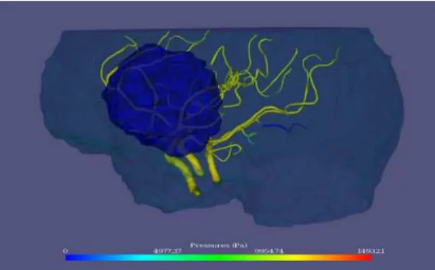
Figure 3 presents a typical example of the vascular network extracted from one of the patients. Semi-transparent cyan surface indicates the approximate limits of the brains. Semi-transparent blue surface indicates a brain tumour.
A. Simulation Results
All the extracted vascular networks were simulated using the proposed approach with and without the model completion method presented in section IV.
The pressure source in all cases was configured with systolic and diastolic pressures (psandpd) of respectively112 and 64
mmHg. Its frequency was set to70 beats per minute. Pressures and flows were evaluated at every0.1s intervals. Colours were assigned based on pressure values computed at every node in the vascular network and linearly interpolated between the nodes along the blood vessels.
Figures 4 and 5 illustrate graphically the simulated pressures in the vessels respectively without and with model completion. In Figure 4, blood vessels always terminate at atmospheric pressure (p = 0), which is unnatural since some of those vessels are rather large arteries that should support a much larger pressure. Any hemorrhage located near the end of one of those vessels would have its flow rate severely underestimated. However, when using completion, the pressure at the end of
the visible vessels is compatible with the vessel size. In Figure 5 the end of the vessels are therefore not blue except for one vessel that was cauterized prior to capturing the image. Hemorrhages near the end of the visible vessels would be much more realistic.
Figure 7 illustrates the effect of the model completion on the simulated flows. Flows in completed models are generally lower and closer to the optimal (predicted by the principle of minimum work) than those terminating at p = 0. Smaller vessels tend, however, to be associated with flow higher than the predicted optimum.
Examples of hemorrhages are presented in Figure 6. As predicted, the velocity of blood ejected out of an hemorrhage is greater at higher blood pressures. In order to avoid large jets and allow for an easier visualization, K was set to a larger than usual value (500) to produce this image. Blood loss, in this case, is visualized by particle systems rendered by Phong splatting [33], [34].
B. Performances
As mentioned previously, computational resources are pre-cious in a surgical simulator. Real-time performance is crucial and many demanding sub-systems compete for resources. Evaluating the performance of the different solving strategies is therefore important. In this context, we implemented and compared two resolution strategies.
First, we used UMFPACK [20], which is a state of the art package dedicated to solving unsymmetric sparse linear systems. UMFPACK needs to build and maintain information
Fig. 3. Typical vascular network extracted from a ToF MRA and used for simulation. Tumor is identified in blue.
Fig. 4. Example of the pressures obtained when simulating a vascular model without virtual vessels.
such as row ordering, LU factors, etc. Thus, the first resolution of a system Ax = b takes significantly longer than further resolutions with different b vectors. We thus tested the two scenarios.
Second, we used the strategy described in the paper, where a non-sparse inverse of the system is maintained and used for resolution. We tested the scenario where the resolution was performed with the inverse matrix (which is basically a matrix multiplication) as well as the scenario where this inverse matrix had to be updated.
Figure 8 presents the average time needed to perform those different operations as a function of the number of elements in the vascular systems (number of nodes and edges combined). The simulations were repeated between5000 (for the shortest experiment) and100 times (for the slowest).
It appears from Figure 8 that the non-sparse resolution tech-nique is more efficient until approximatively 3000 elements when pre-computations do not need to be updated. On the other hand, updating a dense inverse matrix is faster than recomputing the factorization of the sparse system matrix until approximatively 200 elements.
VII. DISCUSSION ANDFUTUREWORKS
Blood circulation and surgical hemostasis are essential aspects of a realistic and useful surgical simulation. We believe that we made a significant contribution by achieving the integration of a live vascular model to a surgical simulator at a realistic computational cost. Feedback from neuro-surgeons
Fig. 5. Example of the pressures obtained when simulating a vascular model completed with virtual vessels at its extremities.
Fig. 6. Example of a generalized cylinder colour-code with pressure values and hemorrhage visualized by splatted spherical particles.
confirm that this component does improve the value of Neu-roTouch as a learning tool. Our experience also helped us identify a certain number of areas where further improvements could be accomplished, especially for applications where a more exact model would be required.
A. Interaction with Surgical Tools
Interactions between surgical tools and the vascular model are still relatively simple in the proposed method. For instance, cauterization operates identically on small and large vessels. It would make sense that the larger vessels be more difficult to cauterize since heat is dissipated over a larger volume.
102 103 104 10−6 10−5 10−4 10−3 10−2 10−1 100 Number of elements Time(s)
UMFPack with refactoring UMFPack without refactoring Sherman−Morrison update Non−sparse resolution
Fig. 8. Time for numerical computations for one simulation time step.
The head loss used for hemorrhages is another example of potential refinement. At the moment, the head loss constant K is a rough estimate that does not change in time or as a function of the context. It is very likely that the nature of the tool used to puncture a vessel changes the flow in the associated hemorrhage. Other factors such as the puncture angle, the velocity of the tool, the vessel size, etc. may also change an hemorrhage’s properties.
We believe that in vitro experiments and in situ observations should be carried out in the future to help refine the constants of the current method and improve interaction models. Given the large number of variables at play, experimental results may also help in determining ranges of acceptable values that could be used to incorporate randomness to the simulation. Experienced surgeons and mentors could also help identifying factors that are important to the learning experience, and possibly help find reasonable parameters for different training scenarios.
One technical challenge that still needs to be addressed is to find a fast and reliable method to distinguish between vessel punctures and vessel ruptures when vessels are rasterized in a three-dimensional texture. At this moment, rasterized vessels will never be ruptured. They will, however, be punctured multiple times which might lead to a similar, but more complex, result. The solution to this problem probably lies with a tighter integration of the soft-tissue dissection method and the vascular model simulation.
B. Quantitative Validation
The current model was qualitatively validated based on feedback from experienced neuro-surgeons and footage of actual surgeries to insure a sufficiently realistic experience for NeuroTouch end-users skill development, which was our main objective. Relative metrics derived from the simulation can already be useful to reinforce learning of good surgical techniques. However, if absolute quantitative metrics were required (such as the actual amount of blood loss during a simulation) to further track a user’s progression or to assess him or her, then more extensive validation would be needed. Two different kinds of validation should then be performed.
First, physical correctness of the models should be assessed using either in situ or in vitro experiments. In situ data could be collected using imaging modalities that would measure simultaneously the geometry of the vascular network and
the flow in its constituting vessels. Hemorrhages may be difficult to study using this strategy, but in vitro experiments using sufficiently realistic vascular phantoms could be used instead. Those experiments would collectively lead to a better understanding of the deviations between the proposed model and the physical phenomena that it simulates. We would then need to determine what deviations are acceptable in the context of surgical training.
A second important kind of validation would therefore evaluate the proposed model as a part of a training method. In other words, it would evaluate under what circumstances and to what extend a blood circulation model leads to better surgical training. Typically, this would involve collecting feed-back from a large number of surgical residents and mentors. Quantitative validation in this context would mean selecting specific tasks, creating quantitative metrics, and comparing the trainees scores with independent performance indicators (number of years into residency, independent scores from their mentors or certification body, etc.).
In both cases, there are several research challenges that will need to be tackled. Some of them are of practical nature while others concern methodological difficulties. Furthermore, both approaches will need a multi-disciplinary team to combine the necessary expertise. We hope to launch new studies to investi-gate those two aspects concurrently as they can be performed independently and will offer complementary conclusions. C. Vascular Model Completion
The vascular model completion method that was proposed does improve the realism of the pressures and flows. Figure 7 also revealed that smaller vessels (less than 1mm in radius approximatively) tend to carry more blood than the principle of minimum work predicts even with virtual vessels acting as downstream vessels equivalence.
There are more than one plausible hypothesis to explain this fact. First of all, it is possible that entire vessel branches are missed during the extraction of the patient-specific model. The under-represented small vessels would then have to carry more blood from the larger arteries. Researching ways to add virtual vessels not only on the leaves of the vascular network, but also on vessels where bifurcations could have been missed would be both useful and challenging. Second, the L2 norm that is minimized to find the virtual vessels’ length
may be exaggerating the importance of large flows in arteries. Perhaps, theL1 norm could lead to improved results. Finally,
the optimization procedure may simply tend to fall into local minimums. This hypothesis is, however, less likely as multiple starting points were tried and did not change significantly the final value of the objective function.
D. Patient-Specific Model Extraction
Flow and pressures are connected via the fourth power of vessels’ radius. The quality of the extracted vascular network therefore has tremendous effects on the simulated flows and pressures.
There exists a large number of alternative methods to segment blood vessels in medical images. Kirbas et al. [35]
and Lesage et al. [36] offer good reviews. However, these methods have different specificity and sensitivity with respect to vessel detection and different accuracy and precision char-acteristics with respect to the measured radii and centerlines of the detected vessels. At this moment, it is still unknown what would be the best segmentation method in the context of vascular flow simulation. A comparative study might be needed in the future.
The accuracy of the vessels’ connectivity is also extremely important to achieve correct hemostatic behaviour. One way to improve patient-specific models would be to inject more prior knowledge into the modelling stage. For instance, Jiang et al. [37] used the principle of minimum work to compute the connectivity of the coronary arteries. The same idea could be transposed to brain vessels. However, anastomosis in the circle of Willis would make this method difficult to apply without further modifications. Furthermore, adaptive detection of the vessels might be helpful to raise the likelihood of finding dimmer vessels where bifurcations are expected.
VIII. CONCLUSION
We proposed in this paper an efficient method to simulate vascular networks and to interact with them during surgical simulations. Moreover, we proposed a method to use incom-plete patient-specific models using the principle of minimum work. The proposed method was validated as a concept by its integration into an existing surgical simulation platform and was also validated in terms of performances.
Real-time performances that were achieved as well as the quality of the resulting simulations lead us to believe that the proposed method should result in better computerized surgical simulators and might, more specifically, open new possibilities to learn and practice surgical hemostasis.
ACKNOWLEDGMENTS
The authors would like to thank all the developers and researchers who contributed to the NeuroTouch platform.
REFERENCES
[1] G. R. Sutherland, I. Latour, and A. D. Greer, “Integrating an image-guided robot with intraoperative MRI: a review of the design and construction of neuroarm,” IEEE Eng Med Biol Mag, vol. 27, no. 3, pp. 59–65, 2008.
[2] S. Misra, K. Ramesh, and A. Okamura, “Modeling of tool-tissue interactions for computer-based surgical simulation: a literature review,”
Presence: Teleoperators and Virtual Environments, vol. 17, no. 5, pp.
463–491, 2008.
[3] U. K¨uhnapfel, H. C¸ akmak, and H. Maaß, “Endoscopic surgery training using virtual reality and deformable tissue simulation,” Computers and
Graphics (Pergamon), vol. 24, no. 5, pp. 671–682, 2000.
[4] J. Qin, Y.-P. Chui, W.-M. Pang, K.-S. Choi, and P.-A. Heng, “Learning blood management in orthopedic surgery through gameplay,” IEEE
Comput Graph Appl, vol. 30, no. 2, pp. 45–57, 2010.
[5] W.-M. Pang, J. Qin, Y.-P. Chui, T.-T. Wong, K.-S. Leung, and P.-A. Heng, “Orthopedics surgery trainer with PPU-accelerated blood and tissue simulation,” Med Image Comput Comput Assist Interv, vol. 10, no. Pt 2, pp. 842–9, 2007.
[6] S. Rianto, L. Li, and B. Hartley, “Fluid dynamic simulation for cutting in virtual environment,” in 16th International Conference in Central
Europe on Computer Graphics, Visualization and Computer Vision.
University of West Bohemia, 2008.
[7] T. Kerwin, H.-W. Shen, and D. Stredney, “Enhancing realism of wet surfaces in temporal bone surgical simulation,” IEEE Trans Vis Comput
Graph, vol. 15, no. 5, pp. 747–58, 2009.
[8] L. Borgeat, P. Massicotte, G. Poirier, and G. Godin, “Layered surface fluid simulation for surgical training.” International Conference on
Medical image computing and computer-assisted interventioon, vol. 14,
no. Pt 1, pp. 323–330, 2011.
[9] J. Cebral and R. Lohner, “Efficient simulation of blood flow past complex endovascular devices using an adaptive embedding technique,”
Medical Imaging, IEEE Transactions on, vol. 24, no. 4, pp. 468–476,
2005.
[10] D. Steinman, J. Milner, C. Norley, S. Lownie, and D. Holdsworth, “Image-based computational simulation of flow dynamics in a giant intracranial aneurysm,” American Journal of Neuroradiology, vol. 24, no. 4, pp. 559–566, 2003.
[11] S. Appanaboyina, F. Mut, R. L¨ohner, C. Putman, and J. Cebral, “Compu-tational fluid dynamics of stented intracranial aneurysms using adaptive embedded unstructured grids,” International Journal for Numerical
Methods in Fluids, vol. 57, no. 5, pp. 475–493, 2008.
[12] L. Grinberg, T. Anor, E. Cheever, J. Madsen, and G. Karniadakis, “Simulation of the human intracranial arterial tree,” Philosophical
Trans-actions of the Royal Society A: Mathematical, Physical and Engineering
Sciences, vol. 367, no. 1896, pp. 2371–2386, 2009.
[13] X. Wu, J. Allard, and S. Cotin, “Real-time modeling of vascular flow for angiography simulation,” Medical Image Computing and
Computer-Assisted Intervention–MICCAI 2007, pp. 557–565, 2007.
[14] S. Tuchschmid, M. Bajka, D. Szczerba, B. Lloyd, G. Sz´ekely, and M. Harders, “Modeling intravasation of liquid distension media in surgical simulators,” Medical Image Analysis, vol. 12, no. 5, pp. 567– 576, 2008.
[15] S. Delorme, D. Laroche, R. Diraddo, and R. Del Maestro, “NeuroTouch: A physics-based virtual simulator for cranial microneurosurgery train-ing,” Neurosurgery, Jan 2012.
[16] M. Olufsen and A. Nadim, “On deriving lumped models for blood flow and pressure in the systemic arteries,” Math Biosci Eng, vol. 1, no. 1, pp. 61–80, 2004.
[17] R. D. Blevins, Applied fluid dynamics handbook. Krieger Pub Co, 1984, p. 558.
[18] Crane(Corporation), Flow of fluids through valves, fittings, and pipe. Crane Co., 2009.
[19] W. H. Guier, G. C. Friesinger, and R. S. Ross, “Beat-by-beat stroke volume from aortic-pulse-pressure analysis,” IEEE Trans Biomed Eng, vol. 21, no. 4, pp. 285–92, Jul 1974.
[20] T. Davis, “Algorithm 832: UMFPACK v4. 3—an unsymmetric-pattern multifrontal method,” ACM Transactions on Mathematical Software
(TOMS), vol. 30, no. 2, pp. 196–199, 2004.
[21] W. H. Press, S. A. Teukolsky, W. T. Vetterling, and B. P. Flannery,
Numerical recipes in C: the art of scientific computing. Cambridge
University Press, 1992.
[22] C. D. Murray, “The physiological principle of minimum work: I. the vascular system and the cost of blood volume,” Proc Natl Acad Sci U
S A, vol. 12, no. 3, pp. 207–14, Mar 1926.
[23] C. Zhu, R. Byrd, P. Lu, and J. Nocedal, “Algorithm 778: L-BFGS-B: Fortran subroutines for large-scale bound-constrained optimization,”
ACM Transactions on Mathematical Software (TOMS), vol. 23, no. 4,
pp. 550–560, 1997.
[24] D. Benson and J. Davis, “Octree textures,” in ACM Transactions on
Graphics (TOG), vol. 21, no. 3. ACM, 2002, pp. 785–790.
[25] J. Gibbs, D. Petty, and N. Robins, “Painting and rendering textures on unparameterized models,” in ACM Transactions on Graphics (TOG), vol. 21, no. 3. ACM, 2002, pp. 763–768.
[26] S. Lefebvre, S. Hornus, F. Neyret, et al., “Octree textures on the GPU,” in GPU Gems 2. Addison-Wesley, 2005, vol. 2, ch. 37, pp. 595–613. [27] V. Mora, D. Jiang, R. Brooks, and S. Delorme, “A computer model of soft tissue interaction with a surgical aspirator,” Medical Image
Computing and Computer-Assisted Intervention–MICCAI 2009, pp. 51–
58, 2009.
[28] D. Jiang, N. Choudhury, V. Mora, and S. Delorme, “Characterization of suction and CUSA interaction with brain tissue,” Biomedical Simulation, pp. 11–19, 2010.
[29] Y. Sato, S. Nakajima, N. Shiraga, H. Atsumi, S. Yoshida, T. Koller, G. Gerig, and R. Kikinis, “Three-dimensional multi-scale line filter for segmentation and visualization of curvilinear structures in medical images,” Medical Image Analysis, vol. 2, no. 2, pp. 143–168, 1998. [30] M. Schneider, S. Hirsch, B. Weber, and G. Sz´ekely, “Physiologically
Image Computing and Computer-Assisted Intervention–MICCAI 2011, pp. 404–411, 2011.
[31] R. Karch, F. Neumann, M. Neumann, and W. Schreiner, “A three-dimensional model for arterial tree representation, generated by con-strained constructive optimization,” Computers in biology and medicine, vol. 29, no. 1, pp. 19–38, 1999.
[32] M. Kretowski, Y. Rolland, J. B´ezy-Wendling, and J. Coatrieux, “Fast algorithm for 3-D vascular tree modeling,” Computer methods and
programs in biomedicine, vol. 70, no. 2, pp. 129–136, 2003.
[33] M. Botsch, A. Hornung, M. Zwicker, and L. Kobbelt, “High-quality surface splatting on today’s GPUs,” in Point-Based Graphics, 2005.
Eurographics/IEEE VGTC Symposium Proceedings. IEEE, 2005, pp.
17–141.
[34] M. M¨uller, D. Charypar, and M. Gross, “Particle-based fluid simulation for interactive applications,” in Proceedings of the 2003 ACM
SIG-GRAPH/Eurographics symposium on Computer animation.
Eurograph-ics Association, 2003, pp. 154–159.
[35] C. Kirbas and F. Quek, “A review of vessel extraction techniques and algorithms,” ACM Computing Surveys, vol. 36, no. 2, pp. 81–121, 2004. [36] D. Lesage, E. Angelini, I. Bloch, and G. Funka-Lea, “A review of 3D vessel lumen segmentation techniques: Models, features and extraction schemes,” Medical Image Analysis, vol. 13, no. 6, pp. 819–845, 2009. [37] Y. Jiang, Z. Zhuang, A. Sinusas, L. Staib, and X. Papademetris, “Vessel
connectivity using Murray’s hypothesis,” Medical Image Computing and