Behavior-based planning and prosecution architecture for
Autonomous Underwater Vehicles in Ocean Observatories
The MIT Faculty has made this article openly available.
Please share
how this access benefits you. Your story matters.
Citation
Balasuriya, Arjuna, Stephanie Petillo, Henrik Schmidt, and Michael
Benjamin. “Behavior-Based Planning and Prosecution Architecture
for Autonomous Underwater Vehicles in Ocean Observatories.”
OCEANS’10 IEEE SYDNEY, 24-27 October, 2010. Sydney, NSW,
Australia, IEEE, 2010.
As Published
http://dx.doi.org/10.1109/OCEANSSYD.2010.5603896
Publisher
Institute of Electrical and Electronics Engineers (IEEE)
Version
Author's final manuscript
Citable link
http://hdl.handle.net/1721.1/120741
Terms of Use
Creative Commons Attribution-Noncommercial-Share Alike
Behavior-Based Planning and Prosecution
Architecture for Autonomous Underwater Vehicles in
Ocean Observatories
Arjuna Balasuriya, Stephanie Petillo, Henrik Schmidt, Michael Benjamin
77 Massachusetts Avenue, Cambridge, MA 02139, USAEmail: [email protected]
Abstract- This paper discusses the autonomy framework
proposed for the mobile instruments such as Autonomous Underwater Vehicles (AUVs) and gliders. Paper focuses on the challenges faced by these clusters of mobile platform in executive tasks such as adaptive sampling in the hostile underwater environment. Collaborations between these mobile instruments are essential to capture the environmental changes and track them for time-series analysis. This paper looks into the challenges imposed by the underwater communication infrastructure and presents the nested autonomy architecture as a solution to overcome these challenges. The autonomy architecture is separated from the low-level control architecture of these instruments, which is called the ‘backseat driver’. The back-seat driver paradigm is implemented on the Mission Oriented Object Suite (MOOS) developed at MIT. The autonomy is achieved by generating multiple behaviors (multiple objective functions) linked to the internal state of the platform as well as the environment. Optimization engine called the MOOS-IvP is used to pick the best action for the given instance based on the mission at hand. At sea operational scenarios and results are presented to demonstrate the proposed autonomy architecture for Ocean Observatory Initiative (OOI).
Keywords: Autonomous Underwater Vehicles (AUVs), Underwater
Gliders, MOOS, MOOS DB, MOOS-IvP, OOI-CI, behavior-based autonomy
I. INTRODUCTION
Marine explorations and sampling is experiencing a paradigm shift from platform-centric to distributed networks of stationary nodes, mobile gliders and autonomous underwater vehicles (AUVs). In order to sample the hostile, wide area of the ocean and to conduct time-series analysis of these important unknown ocean processes, it is necessary to have these sensor nodes continuously sample the environment and react to the changes in the field. It is hard to capture these ocean processes using stationary moorings or mobile platforms with smaller apertures. It is necessary to come up with new concepts of operations to capture these natural phenomena autonomously and change the sampling strategies to track these features to understand the ocean better.
Adaptive ocean sampling methods have been demonstrated previously by a fleet of gliders [3]. Due to low-power consumption gliders are capable of operating for long durations compared to propelled AUVs [4]. Gliders depend on the ocean currents for their movement which makes it hard to control. On the other hand AUVs can control their own motion and can change their trajectories to changing environmental features. Such reactive behavior is necessary for adaptive ocean sampling. In order to introduce intelligent data-gathering to a cluster of underwater vehicles, it is necessary that they have some sort of communication. Most of the commercially available AUVs are fitted with acoustic modems. Due to low bandwidth, latencies and communication uncertainties, underwater communication infrastructures cannot be used as the back-bone of the sensor network. The micro-modem manufactured by Woods Hole Oceanographic Institute can go up to eight 256-byte frames per packet [1]. Due to underwater severe multipath reflections, curved propagation paths due to uneven temperature distribution, etc. the communication can have latencies and loss of data. Due to these limitations in underwater acoustic communication, the underwater mobile sensor network cannot be built on such communication infra-structure. This paper proposes the ‘nested autonomy architecture’ where each mobile node will be intelligent to take action to the changing environmental conditions without depending much on the communication infra-structure. Using the low-bandwidth communication network each node will broadcast its status and detected feature positions. These updates from nodes in the cluster will activate collaborative behaviors in each node.
In Section 2 a brief description is given on the Ocean Observatory Initiative (OOI) sponsored by the National Science Foundation (NSF). Section 3 discusses the behavior-based MOOS-IvP architecture. The Observing System Simulation Experiment (OSSE) conducted in 2009 is presented in section 4 and the conclusions from these at sea experiments are discussed in section 5.
II. OCEANOBSERVATORYINITIATIVE
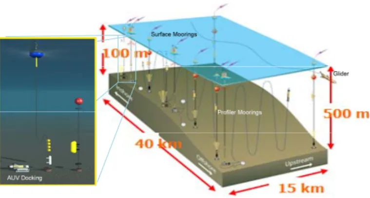
Ocean Observatory Initiative (OOI) is sponsored by the NSF and is currently under construction. By the end of year 2015 it is expected that there will be 3 global scale, 5 regional scale, 2 coastal scale nodes in place and all these will be connected through the cyber-Infrastructure (CI). The science and operations community will have access to these Costal, Global, and Regional Scale Nodes (CGRSN) through CI. Global and coastal scale nodes will be equipped with gliders and AUVs for adaptive ocean sampling missions. AUVs will be docked to these observatories for charging their batteries and to exchange data as shown in Fig. 1. During operations the observatory will talk to the vehicles via acoustic modems.
Fig. 1: Observatory Setup, courtesy of OOI-CI
During operations AUVs will be communicating mainly their status information to the observatory and the observatory will be sending high level commands such as mission changes to the AUV. At present gliders are not equipped with modems and they communicate via satellite communication links when they surface. On completion of an operation AUVs docks onto the observatory to transfer collected data as well as to charge their batteries. During operations AUV carry out its mission using the on-board intelligence and depend less on the communication network. Net-centric nested autonomy architecture is discussed in the next section.
III. NESTED AUTONOMY ARCHITECTURE The objective of the Nested Autonomy is to enhance the system performance beyond what is achievable by the autonomy on-board a node. This is associated with the inherent layering of the communication infrastructure, with the underwater network connectivity being provided by low-bandwidth acoustic communication (ACOMMS), and the above-surface networking being provided by high-bandwidth, but latent, radio frequency (RF) communication through a regularly surfacing gateway node. On-board each node, the computer bus and ethernet networking provide very high bandwidth communication between the sensing, modeling and control processes. The bandwidth ranges from 100byte/min for the acoustic communications to 100Mbyte/min for the on-board
communication. Similarly the communication channels have latencies and intermittencies ranging from virtually instantaneous connectivity of the on-board sensors and control processes to latencies of 10-30 min for information flowing to and from the observatory planners. This, in turn, has critical implication to the time scales of the adaptability and collaborative sensing and control. Due to these latencies and intermittencies with the observatory, small scale adaptivity, such as autonomously reacting to the episodic environmental events or tracking a detected feature must clearly be performed without the observatory intervention.
The core of the nested autonomy paradigm is the autonomous, integrated sensing, modeling and control, command and control framework on each individual platform. In combination with the collaborative cluster autonomy, the integrated node autonomy enables the environmental and tactical adaptivity, which may compensate for the reduced physical acoustic apertures of the AUVs.
A. The MOOS-IvP Autonomy Architecture
The Autonomous Command, Control and Communication
(AC3) nested autonomy is implemented within the MOOS-IvP
architecture for autonomous control, developed and maintained under a GPL license by MIT, Oxford University, and NUWC. MOOS-IvP is composed of the Mission Oriented Operating Suite (MOOS), an open source software project for communication between, and nested control and coordination of, software processes running on the nodes of network of autonomous platforms [2]. iRTSon MOOS DB Acoustic Samples Status Control Real-time Sonar Interface pHelmIvp Adaptive, Behavior-based AUV Control
Vehicle Nav, Data
Data Acomms Commands iMicroModem MOOS-MVC Interface pHuxley Heading Speed Depth Vehicle NAV Status Heading, Speed Depth WHOI Micromodem BF21 MVC Main Vehicle Computer NMEA CCL Vehicle Nav Results pSigProc Signal Processing Environmental Parameters
Fig. 3: Example of a MOOS tree on-board Bluefin 21’ AUV MOOS is a publish/subscribe architecture where each MOOS process interact each other via the ‘bulletin board’ MOOS DB as illustrated in Fig. 3. The exact copy of the moos-tree, except the processes which talk to hardware, can be used in simulation by replacing the hardware with a software model. MOOS-IvP is fully portable and platform independent, but typically implemented under GNU/Linux. MOOS-IvP also contains the IvPHelm shown in Fig. 4, a behavior-based helm that provides the core of the behavior-based control architecture [2]. The IvP-Helm runs as a single MOOS process as shown in Fig. 3,
and uses multi-objective optimization with the Interval Programming (IvP) model for behavior coordination. The MOOS processes include all necessary control functions as well as sensing and processing modules, with the MOOSDB providing the unified interface standard that enables the fully autonomous integration of sensing, modeling and processing, and control.
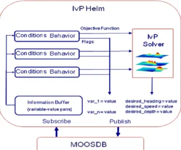
Fig. 4: IvP-Helm is MOOS Process called pHelmIvP in the MOOS community
The IvP Helm, as a software module, can be viewed as an interface between the set of behaviors and the MOOSDB and the other system components connected to MOOSDB. Its primary function at run time is to arbitrate between behaviors by soliciting objective functions from each, over a common decision space, and performing multi-objective optimization. Besides posting the resulting decision to the MOOSDB, the helm also posts other variable-value pairs based on requests of the behaviors generated during the behaviors’ function producing iteration. This includes state information that one behavior may communicate to another across iterations, such as a condition that marks the completion of one behavior and triggers the activation of another as described by the CONDITION and ENDFLAG parameters below. The helm, upon startup, reads a configuration, i.e., mission, file with sets of parameters. The key parameters for behaviors used in experiments reported here are described in the following sections. An important component of our research objectives is to allow behaviors to be adaptive not only to environment events, but also to periodic direction from field control. This means a mission file is not a static script with a start and completion, but more aptly described as a state space with an initial state and conditions for migrating between states based on events; mission-control, environment or otherwise.
Following parameters describe properties inherited by all behaviors.
PRIORITY: The priority weight of the produced objective function. A behavior may also be implemented to dynamically determine its own priority weight.
DURATION: The time duration before the behavior is marked completed. If none provided, the behavior will not time-out. The clock begins when the behavior first becomes active. CONDITION: A condition that must be satisfied for the behavior to be active. It is a equal-separated pair such as DEPLOY =true. If more than one condition is given, they all must be satisfied. The variables are MOOS variables and the helm automatically subscribes to a variable appearing as a behavior condition.
RUNFLAG: A variable and a value posted while the behavior is active. It is a equal-separated pair such as TRANSITING=true. More than one runflag may be provided and can be used to satisfy or block the conditions of other behaviors.
ENDFLAG: A variable and a value posted when the behavior has completed. The circumstances causing completion are unique to the individual behavior, but if any behavior has a DURATION specified, the endflags are posted upon time-out. The value of this parameter is a equal-separated pair such as ARRIVED HOME=true.
UPDATES: A MOOS variable from which updates to behavior parameters are read from after the behavior has been initially instantiated and configured at the helm startup time. Any parameter and value pair that would have been legal at startup time is legal at runtime. This is one of the primary hooks to the helm for mission control; the other being the behavior conditions described above.
B. The Back-Seat Driver Paradigm
To allow the MOOS-IvP network control to be applied on a variety of fixed and moving nodes with different control software, a “back-seat driver” paradigm was adopted and integrated with the MOOS-IvP control software infrastructure. The idea is that all high-level control, including the adaptation to measured and estimated parameters, is performed in a payload computer (PLC) running MOOS-IvP. The PLC will also handle all communication with the network, either through a radio link while surfaced, or an acoustic modem when submerged. All lower level control, and basic navigation and platform safety tasks are handled by the native vehicle control software running in the main vehicle computer (MVC), i.e. Huxley in the case of the Bluefin AUVs. The communication between the PLC and the MVC is performed over an ethernet socket, operated by a MOOS process pHuxley running on the PLC, as illustrated in Fig. 4. The commands passed to the MVC are simply continuous updates of desired heading, speed and depth, which the MVC then translates to desired rudder, thrust and elevator signals to the tail cone. The MVC will return current navigation and state data, which pHuxley will then publish in the MOOSDB. . In this architecture, the PLC appears to the MVC as a simple NMEA (NMEA is an industry standard for communication between marine devices) device, and vice versa. The basic safety tasks performed by the MVC
include mission abort due to bottom altitude limit violations, and lack of commands from the PLC in a certain specified time, as well as an overall mission timeout. Higher level safety tasks such as exceeding the specified operating radius, and individual behavior timeouts or failures, are handled by the PLC.
IV. OBSERVING SYSTEM SIMULATION EXPERIMENT
(OSSE)
Interactive Observatory Facility Services
Portable Control SW Event Response Services Multi Objective Observation Catalog Event DB/Model facility/asset protection services Planning Services Includes ASPEN, facility/asset protection services Data & event notices Responses Mission Simulator Plans or commands to control SW Includes MOOS/IvP and CASPER Onboard Autonomy Shore-Side Planning
Fig. 5: Planning and Prosecution Modules
In order to demonstrate the ‘back-seat’ driver paradigm along with the Jet Propulsion Laboratory (JPL) planners [5], an experiment was conducted in the Mid-Atlantic Bight.
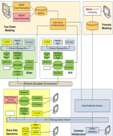
Fig. 6: Software Module Dependencies in OSSE
Planning and Prosecution sub-system under the OOI-CI will be delivering these services by the end of year 2015. Concept of operation is described in Fig. 5. There are two components for the JPL planner. ASPEN act as the shore-side planner and will reside on the observatory side and CASPER will be on-board an AUV interacting with the MOOS-IvP Autonomy. Software module dependencies are described in Fig. 6.
Experiment consisted of 5 environmental models, 4 Slocum gliders, 3 AUVs, and 1 Satellite pass. Gliders were not equipped with micro-modems so they communicated to the shore using SATCOM when they were on surface. AUVs communicated through using ACOMMS as shown in Fig. 7. The gateway buoy has a radio link to the supporting ship R/V Arabella. MIT Top side was setup on the ship and the planner was running at JPL. Based on the environmental models the planner picked the operation box and conveyed it to the top side. Top side then sent a re-deploy message to the AUVs using the acoustic link.
Fig. 7: Experimental Setup for OSSE
AUVs were deployed to carry out different tasks such as loitering and environment sampling. Three AUVs participated in this experiment were; REMUS, and 2 IVERs as shown in Fig. 8.
V. CONCLUSIONS
Planning and prosecution sub-system capabilities were demonstrated at sea by implementing the planning algorithms and the MOOS-IvP behavior-based autonomy architecture on AUVs. The implementation of the back-seat driver autonomy was similar for all the three AUVs. Only difference was how each vehicle’s behaviors were captured. The communication infrastructure was tested and commands were sent to the AUVs while they were operating underwater and their missions were changed. Top side situation display was able to receive status messages from these vehicle while they were operating and was able to feed these updates to the Google Earth enabling scientists in different parts of the world to see the experiment in real-time.
ACKNOWLEDGMENT
The authors would like to thank the JPL for information on ASPEN/CASPER planners, OOI-CI team for their suggestions and the Rutgers team and California Polytechnic team for their support during the experiments.
REFERENCES
[1] Acoustic communication group, “Micro-Modem Software Interface Guide”, WHOI, Document ID: 401040, Ver. 3.03, Feb. 25, 2010
[2] Michael Benjamin, Paul Newman, Henrik Schmidt and John
Leonard,”Extending a MOOS-IvP Autonomy System and Users Guide to the IvPBuild ToolBox”, MIT CSAIL Tech. Report TR-2009-037, August
2009.
[3] Edward Fiorelli, Naomi Ehrich Leonard, Pradeep Bhatta, Derek Paley, Ralf Bachmayer, David M. Fratantoni, “Multi-AUV Control and Adaptive Sampling in Monterey Bay”, Proc. of IEEE AUVs 2004, June
2004.
[4] Oscar Schofield, Josh Kohut, David Aragon, Liz Creed, Josh Graver, Chip Haldeman, John Kerfoot, and Hugh Roarty, Clayton Jones, Doug Webb and Scott Glenn, “Slocum Gliders: Robust and Ready”, J. of Field
Robotics, 2007.
[5] David R. Thompson, Steve Chien, Arjuna Balasuriya, Stephanie Petillo, Yi Chao, Peggy Li, Bronwyn Cahill, Julia Levin, Michael Meisinger, Matthew Arrott, Oscar Schofield. “Spatiotemporal Path Planning in Strong, Dynamic, Uncertain Currents”. Proc. of the IEEE International