Publisher’s version / Version de l'éditeur:
Vous avez des questions? Nous pouvons vous aider. Pour communiquer directement avec un auteur, consultez la première page de la revue dans laquelle son article a été publié afin de trouver ses coordonnées. Si vous n’arrivez pas à les repérer, communiquez avec nous à [email protected].
Questions? Contact the NRC Publications Archive team at
[email protected]. If you wish to email the authors directly, please see the first page of the publication for their contact information.
https://publications-cnrc.canada.ca/fra/droits
L’accès à ce site Web et l’utilisation de son contenu sont assujettis aux conditions présentées dans le site LISEZ CES CONDITIONS ATTENTIVEMENT AVANT D’UTILISER CE SITE WEB.
Proceedings of the 2011 15th International Conference on Computer Supported
Cooperative Work in Design (CSCWD), pp. 649-656, 2011-06-08
READ THESE TERMS AND CONDITIONS CAREFULLY BEFORE USING THIS WEBSITE. https://nrc-publications.canada.ca/eng/copyright
NRC Publications Archive Record / Notice des Archives des publications du CNRC :
https://nrc-publications.canada.ca/eng/view/object/?id=9fcbc8c3-46d7-4ae1-9537-b8fd824f3644
https://publications-cnrc.canada.ca/fra/voir/objet/?id=9fcbc8c3-46d7-4ae1-9537-b8fd824f3644
NRC Publications Archive
Archives des publications du CNRC
This publication could be one of several versions: author’s original, accepted manuscript or the publisher’s version. / La version de cette publication peut être l’une des suivantes : la version prépublication de l’auteur, la version acceptée du manuscrit ou la version de l’éditeur.
For the publisher’s version, please access the DOI link below./ Pour consulter la version de l’éditeur, utilisez le lien DOI ci-dessous.
https://doi.org/10.1109/CSCWD.2011.5960187
Access and use of this website and the material on it are subject to the Terms and Conditions set forth at
Integration of indoor localization with facility maintenance
management
I nt e gra t ion of indoor loc a liza t ion w it h fa c ilit y m a int e na nc e
m a na ge m e nt
N R C C - 5 4 4 2 5
S u n , H . ; X u e , H . ; S h e n , W . ; H a o , Q . ; X i a o , T .
A u g u s t 2 0 1 1
A version of this document is published in / Une version de ce document se trouve dans:
15th International Conference on Computer Supported Cooperative Work in
Design (CSCWD 2011), Lausanne, Switzerland, June 8-10, 2011, pp. 1-8
http://www.nrc-cnrc.gc.ca/irc
The material in this document is covered by the provisions of the Copyright Act, by Canadian laws, policies, regulations and international agreements. Such provisions serve to identify the information source and, in specific instances, to prohibit reproduction of materials without written permission. For more information visit http://laws.justice.gc.ca/en/showtdm/cs/C-42
Les renseignements dans ce document sont protégés par la Loi sur le droit d'auteur, par les lois, les politiques et les règlements du Canada et des accords internationaux. Ces dispositions permettent d'identifier la source de l'information et, dans certains cas, d'interdire la copie de documents sans permission écrite. Pour obtenir de plus amples renseignements : http://lois.justice.gc.ca/fr/showtdm/cs/C-42
Integration of Indoor Localization
with Facility Maintenance Management
Hongbo Sun1,2, Henry Xue1, Weiming Shen1, Qi Hao1, Tianyuan Xiao2
1
Centre for Computer-assisted Construction Technologies National Research Council Canada, London, Ontario, Canada
2
National CIMS Engineering Research Centre, Tsinghua University, Beijing, China [email protected], [henry.xue; weiming.shen; qi.hao]@nrc.gc.ca
Abstract—This paper proposes an architecture for integration
of indoor localization systems and decision support systems and/or manufacturing executive systems. In this paper, an indoor localization integration architecture is introduced under the scenario of an intelligent building localization system to uncover the relations among the necessary components and functions. Implementation details are also thoroughly explored, including class diagrams, work flows and the interface of the key component. The proposed architecture has the advantages of scalability and reconfigurability. In this architecture, different types of wireless sensors technologies including WiFi, ZigBee and RFID can be integrated simultaneously to support “smart environments”. Information from different data sources is transparent to information consumers (application systems), which means they can track “real” time position information of the interested assets in spite of the data sources. An application has been designed and implemented with the proposed architecture.
Keywords—Wireless sensor network, Localization, WiFi,
RFID.
I. INTRODUCTION
Wireless sensor networks have become a key technology for different types of “smart environments”. As a result, an intense research effort is currently underway to enable the application of wireless sensor networks for a wide range of industrial problems. [1]
Recently, there has been a growing interest in the design, development and deployment of sensor systems for applications of high-level inference, which has lead to an increasing demand on interconnecting wireless sensor networks with other emerging technologies [2], such as RFID technology [3], multimedia-based surveillance systems [4], biomedical technology [5], mobile agent-based networks [6], P2P technology and business processes [7] and semantic technology [8]. With sensor technology being incorporated into these technologies, demands from an increasing number of autonomous and intelligent applications can be met.
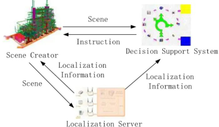
In an intelligent building, facilities or electronic appliances have to work in harmony in order to offer the occupants more convenient and smart services. Some of these services are location-based, such as the occupancy and lighting system, both based on human location, and the garage gate control, based on car location. This kind of localization is an indoor location problem. Other than outdoor localization problem that
uses GPS as the main technology, different wireless sensor technologies should be integrated in order to get a high resolution for the signal shield of buildings. One example has been in intelligent building facility maintenance where generic position information is needed from localization systems in line with the created scene which supports the decision support systems and/or indoor applications (Figure 1). An effective localization algorithm can then use all the available information from the wireless sensor nodes to infer the position of the individual devices.
Scene Creator Decision Support System
Localization Server Scene Scene Localization Information Instruction Localization Information
Figure 1. A building localization system application scenario
A sensor can know its own location either via a built-in GPS-like device or a localization technique. A straightforward localization approach would gather the information (e.g. connectivity, pair-wise distance measure) about the entire network into one place, where the collected information is processed centrally in order to estimate the sensors' locations using mathematical algorithms, such as Semi-definite Programming and Multidimensional Scaling. However, at the same time, many techniques attempt localization in a distributed manner. The relaxation-based techniques start with all the nodes in their initial positions and then they keep refining their positions using algorithms such as local neighborhood multilateration and convex optimization. The coordinate-system stitching techniques divide the network into overlapping regions, with nodes in each region being positioned relative to the region's local coordinate system (a centralized algorithm may be used here). The local coordinate systems are then merged, or “stitched”, together to form a global coordinate system. Localization accuracy can be
improved by using a set of beacons that extrapolate unknown node locations from the beacon locations.
Besides position information, wireless sensors can also provide other information to support various applications. However, the information providers need middleware to make them well-organized and work harmoniously.
The aim of this work is to develop middleware with multiple measurements to coordinate the different types of
wireless systems in the Lab and provide various pieces of information for different applications. This method takes advantage of, not only algorithms on a distributed environment and executed in individual nodes, but also schemes that pool all data from the network and perform a centralized computation. The technologies involved in the system integration include ZigBee, WiFi and RFID systems.
II. ARCHITECTURE A p p l i c a t i o n s ( F M M ) L o c a l i z a t i o n S e r v i c e C e n t r e APP Intefaces Fetching Agent(C#) Internal Database Web Services (.net) Wifi API Enterprise Portal(JSP) Administrator Workbench Wifi Engine Zigbee API Zigbee Engine Rfid API Rfid Engine
Figure 2. Integration Architecture of Sensor Systems
This architecture describes the integration framework for localization systems (Figure 2). Applications access all kinds of localization data via .net web services. Users configure the Localization Service Centre by Administrator Workbench, set the parameters of fetching agent (C#) or retrieve the statistical data via Enterprise Portal (JSP). The internal database stores history localization data, configuration settings, user information and settings. The Localization Service Center integrates APIs of different localization systems, RFID, ZigBee and WiFi. For extensibility reasons all APIs present themselves as web services.
As Figure 3 shows, the detailed implementation architecture of localization systems integration can be separated into five parts: business explorer, web services interface, administrator workbench, supporting services and database.
The business explorer is the interface between the software and the users. The Enterprise portal provides a web-based interaction method to configure, monitor and control the whole system. The Fetching agent is more useful for passive localization updating systems which constantly updates the localization information to given applications. The common functions of business explorer are state monitor, access control, execution control, configuration management, fault tolerance control,
The Web services interface supports the business explorer and 3rd party applications by web services. It provides abilities such as, getting information, controlling execution, setting configuration parameters, controlling authentication access and reporting logs.
The Administrator workbench gathers all of the abilities of the configuration parameter settings.
The database is used to store the raw data and all kinds of information needed or generated by this software. It can be more than one physical database according to the system scale. The databases can also be deployed on distributed physical computational nodes.
Supporting services is a type of middleware which performs the key operations of this software. Above the hardware layer, there are 6 layers: data source, representation, information, dispatch (Agent), coordinator and the formalization layer. The hardware layer deals with all the hardware involved and offers different methods to communicate among them. All the low level systems that are closely related to the hardware are looked upon as data sources. The representation layer transforms raw data from the lower level to a unique format in order that the whole system has a unique data representation semantic. After the computation, the engines feed data to the database as information according to the representation settings. The Dispatch layer has one or several agents, working together harmoniously to fulfill the application requirements. The Service center registers all the abilities provided by this software and the fetching application services served by the agent layer. When some user requirements reach this layer, privilege control will check the authentication information first, and then organize a proper workflow to satisfy these requirements. The script layer gives a formal description of all the abilities provided.
The kernel of this architecture is the service center, which is in charge of web services registration and workflow organization.
In some architecture, the portal may directly access the services provided by lower level systems. But from the view of reuse and security this architecture only allows portal access to lower level services by well-established web services. And, at the same time, these web services are also very important to third party applications. These applications can only access this system by these web services.
Representation management is the main part related to heterogeneous sensor systems; only in this way can representation heterogeneousness be eliminated before the data goes into this system as meaningful information.
The Dispatch layer can be as simple as only mapping requirements to the data source or be as complicated as several agents being used for work load balancing and work transmission.
Computing engines in this architecture are deemed as separated data sources, and because the factory pattern
will be used in the future implementation, new computing engines can be easily added into this system.
The Script layer is not the most necessary layer in the whole system, but it is most useful for evaluation of this system and the application heterogeneousness can be easily erased by this layer.
As the first step toward the development of the above architecture, the rest of this report will focus on the integration of the AeroScout Wifi-RFID system with the Facility Maintenance Management (FMM) system.
III. IMPLEMENTATION
A. Interfaces Provided by Web Service Interface
• Grouping Services
o Group and unGroup
Group and ungroup a set of assets by a given UUID list from FFM. After the success of grouping, the information of the group of assets can be retrieved from the location system by calling the group name.
• Localization Services o getLocationData
Get location data from localization systems by a list of assets.
B. Fetching Agent Class Diagram and Interface
As Figure 4 shows, the fetching agent can be divided into three parts: log window, configuration panel and command panel. The log window presents background events performed by this software. The configuration panel sets the initial parameters of the current execution. The Host is the IP address of the localization services. The User and Pwd are the authentication information of the localization services. The Sens and Freq set the sensitivity and frequency of the moving detection for the passive updating localization systems, respectively. The command panel contains interactive buttons to change the current execution. The Connect makes the connection with the localization services. The Start begins to scan the position changing from the localization system. The Reset updates the parameter settings according to the configuration panel; and the End button triggers the stop event of the current execution.
C. Fetching Agent Workflows
• Initialization process
The initialization process, Figure 5, is launched when the start button is clicked. This includes a bi-directional hand-shaking process by getting a list of the assets residing in FMM (getFMMAssetIDList), matching the list with assets in the localization System, and setting a list of traceable assets for FMM (setTrackableAssetList).
Figure 4. Fetching Agent Class Diagram.
Figure 5. Initialization Process Workflow.
w_main: : WSNAgent myBusinessRule :
BusinessRule myFMMInterface : FMMInterface myDataAccess : DataAccess myAeroScoutInterface : AeroScoutInterface 1: getAssetsTrackingRequirement( ) 2: getFMMAssets( ) 3: assetIDmapping( ) 4: getTracableAssetIDs( ) 5: assetID 7: getInitialLocations( ) 6: initialLocation 8: saveLocalization( ) 9: UUIDmapping( ) 10: setTracableAsset( ) 11: TrackableAssetCount 12: setRefreshParameters( ) 13: startRefresh( ) 14: appendLog( )
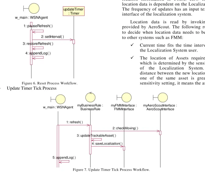
• Reset process
The reset process, Figure 6, is launched when the reset button is clicked. It resets the interval of the timer and the sensitivity of moving detection.
Figure 6. Reset Process Workflow.
• Update Timer Tick Process
The Update Timer Tick process, see Figure 7, is launched every given time period. It updates the localization information of each required asset. The Localization agent constantly pushes the assets’ location information to FMM. How to update the location data is dependent on the Localization systems. The frequency of updates has an input text box on the interface of the localization system.
Location data is read by invoking the APIs provided by AeroScout. The following rules are used to decide when location data needs to be “pushed” to other systems such as FMM:
Current time fits the time interval setting by the Localization System user.
The location of Assets required is moved, which is determined by the sensitivity setting of the Localization System. When the distance between the new location and the old one of the same asset is greater than the sensitivity setting, it means the asset moved.
Figure 7. Update Timer Tick Process Workflow.
IV. RELATED ISSUES
A. Matching assets using UUID
A Universally Unique Identifier (UUID) is an identifier standard used in software construction, standardized by the Open Software Foundation (OSF) as part of the Distributed Computing Environment (DCE). The intent of UUIDs is to enable distributed systems to uniquely identify information without significant central coordination. A UUID may also be used with a specific identifier intentionally used repeatedly to identify the same thing in different contexts.
An UUID is a 16-byte (128-bit) number. The number of theoretically possible UUIDs is therefore about 3 × 1038. In its canonical form, a UUID consists of 32 hexadecimal digits, displayed in 5 groups separated by hyphens, in the form 8-4-4-4-12 for a total of 36 characters (32 digits and 4 hyphens). For example:
550e8400-e29b-41d4-a716-446655440000
The assumption for matching assets in multiple application systems is that each asset in the real world has a Universal Unique Identification code (UUID) that all systems know beforehand. The UUID is first issued to both FMM and Localization systems by the BIMServer when an asset element is created in the IFC model.
The UUIDs of the same asset used in the FMM and BIM system are different because of the generation method. For example, asset 521 (in AeroScout location system) is represented as 521e8728798-7b8b-3d0c-889f-f8facafaf70d in BIM, while in FMM it is represented as 2dc3a985-3bcd-4503-b525-faa00608f8c2. Hence, these two different representation mappings should be stored separately.
B. Showing locator map
The FMM system uses a URL API provided by AeroScout Mobile View to show assets on a map. Since the API only provides a single value search in its Locator, FMM needs to “group” multiple assets together in order to show multiple assets on the map. The URL for searching a FMM group is:
w_main : WSNAgent updateTimer : Timer 4: appendLog( ) 1: pauseRefresh( ) 2: setInterval( ) 3: restoreRefresh( )
w_main : WSNAgent myBusinessRule :
BusinessRule myFMMInterface : FMMInterface myAeroScoutInterface : AeroScoutInterface 5: appendLog( ) 1: refresh( ) 2: checkMoving( ) 3: updateTrackableAsset( ) 4: saveLocalization( )
http://<AeroScoutHost>:8080/asset-manager-web/pages/ accessServlet? screenId= locator&searchValue=FMM [Note] Use part of the name of an asset as the search value for showing a single asset on the map. <AeroScoutHost> in the URL needs to be replaced with the IP address of the web server of AeroScout Mobile View.
C. AeroScout APIs
AeroScout provides its API in the form of Web Services as follows [8]:
• AreaAPIService: Provides functions for manipulating
Locations, Areas and Zones.
• AssetAPIService: Provides functions for Asset
management.
• AssetBusinessStatusAPIService: API for fetching Asset
Business Status Entities.
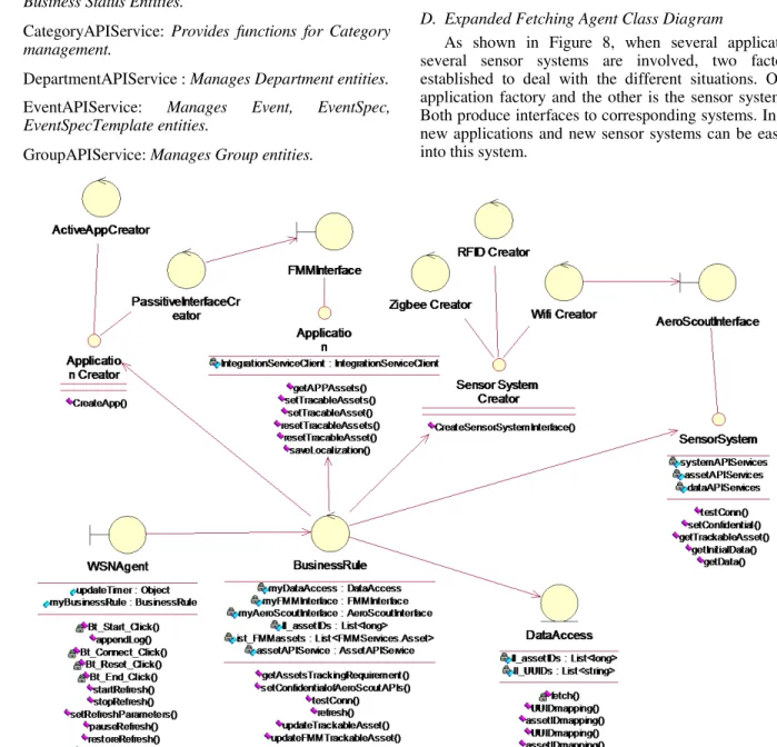
• CategoryAPIService: Provides functions for Category
management.
• DepartmentAPIService : Manages Department entities. EventAPIService: Manages Event, EventSpec, EventSpecTemplate entities.
• GroupAPIService: Manages Group entities.
• LocatorAPIService: Provides functions for querying
the different types of Location Reports.
• PermissionAPIService: Manages Permission entities. • RoleAPIService: Manages Role entities.
SystemAPIService: For non-specific system calls. For
example, use this to get the latest API version.
• TagAPIService: Manages Tag entities. • UserAPIService: Manages User entities.
What we use in this system are systemAPIService, assetAPIService and locatorAPIService. SystemAPIService is used for testing the connection to AeroScout Engine by checking if it can get the right AeroScout Engine version. AssetAPIService is used to get asset information in AeroScout. LocatorAPIService is used to get location information.
D. Expanded Fetching Agent Class Diagram
As shown in Figure 8, when several applications and several sensor systems are involved, two factories are established to deal with the different situations. One is the application factory and the other is the sensor system factory. Both produce interfaces to corresponding systems. In this way, new applications and new sensor systems can be easily added into this system.
V. CASE STUDY
This case is designed for the validation of the integration of AeroScout’s location engine to our indoor FMM system. All necessary services and codes for Fetching Agent are finished before starting this case.
The localization related services in FMM are written in Java and deployed by Apache Geronimo2. The invoked localization services of the AeroScout system are written in Microsoft .net and deployed in the Internet Information Services.
All necessary components are deployed as shown in Figure 9. The Localization Server reads the localization data of the active tags according to the settings of the AeroScout system. The Fetching Agent reads the localization data of the assets which bind with some active tags from the Localization Server by invoking related web services at times. After determining the movement, it maps the moved assets of the AeroScout system to the FMM assets and updates their locations by invoking the related web services of the FMM system. When the FMM system needs to show the localization information of the given assets group, it first invokes Group Service of Fetching Agent. Then the FMM system redirects to the URL of Mobile View with the group name as a parameter. The location information will be displayed in Mobile View web page.
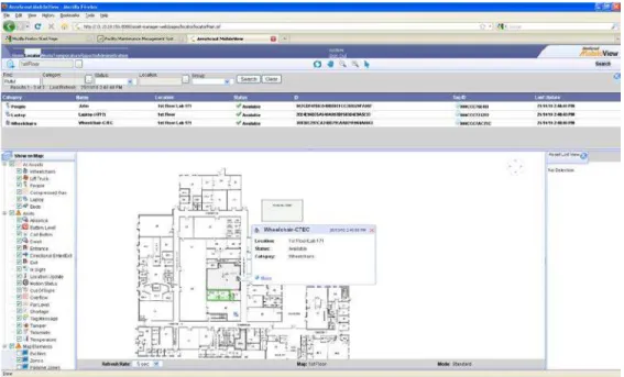
After all the preparations are finished, including codes, web services, AeroScout settings, and API tests, the first step is to start all the web services needed and the Fetching Agent. According to the requirements demonstrated in Figure 5, in this case the frequency is set to 30 seconds. And the sensitivity is about a half meter. When the distance between the old location and the new location exceeds that threshold, the Fetching Agent will update the location information in the FMM system, which can show the latest locations of the traceable assets (Figure 10).
A 2.5-D “real” time demonstration of the given active assets can also be viewed with the Mobile View web pages (Figure 11).
Comparing with locations of corresponding assets in the Localization server, the synchronization delay of location data is acceptable and no information is lost.
Figure 9. Deployment of Components.
Figure 10. Location Data in FMM system
Figure 11. Mobile View invoked by FMM system
Tags Fetching Agent Localization Server FMM Mobile View <<WiFi>> <<Web Services>> <<Web Services>> <<http>>
VI. CONCLUSION
This paper summarized the design and implementation of the indoor localization systems with FMM. It presented the architecture, interfaces and web services. The AeroScout Wi-Fi-RFID system has been integrated with an indoor FMM system. By request, the web services provide locations and other information of the assets from the AeroScout location engine to the FMM. It also pushes data to the FMM when the asset location information is updated.
In the proposed integration architecture, other wireless sensor systems (such as WiFi, ZigBee and RFID technologies respectively) can be loosely coupled and can work complementarily to support different requirements for various kinds of applications in smart environments. The same asset existing in different systems can automatically be mapped to each other. And the application systems can get real-time location information regardless of which localization system it is from.
REFERENCES
[1] Ichiro Satoh. “A location model for smart environments”. Pervasive and Mobile Computing, vol. 3, pp. 158-179, 2007.
[2] Jennifer Yick, Biswanath Mukherjee and Dipak Ghosal. “Wireless sensor network surbey”. Computer Networks, vol.52(12), pp.2292-2330, 2008.
[3] Hai Liu, Miodrag Bolic, Amiya Nayak and Ivan Stojmenovic. “Taxonomy and Chanllenges of the Integration of RFID and Wireless Sensor Networks”. IEEE network. Vol. 22(6), pp. 26-32,2008.
[4] Xiangjun Zhu, Shaodong Ying and Le Ling. “Multimedia sensor networks design for smart home surveillance”. Proceedings of Chinese 2008 Control and Decision Conference, Yantai, Shandong, China, pp. 431-435, 2008.
[5] Jeonggil Ko, Tia Gao, Richard Rothman and Andreas Terzis. “Wireless Sensing Systems in Clinical Environments”. IEEE Engineering in Medicine and Biology Magazine, Vol.29(2), pp.103-109, 2010.
[6] Mert Bal, Weiming Shen and Hamada Ghenniwa. “Collaborative Signal and Information Processing in Wireless Sensor Networks: a Review”. Proceedings of the 2009 IEEE International Conference on System, Man, and Cybernetics, San Antonio, TX, USA, pp. 3151-3156, Oct. 2009. [7] Gustavo Gutierrez, Boris Mejias, Peter Van Roy, Diana Velasco and
Juan Torres. “WSN and P2P: a self-managing marriage”. Proceedings of 2008 Second IEEE Inernational Conference on Adaptive and Self-Organizing System Workshops, Venice, Italy, pp. 198-201,2008. [8] Vincent Huang and Muhammad Kashif Javed. “Semantic Sensor
Information Description and Processing”. Proceedings of the second International Conference on Sensor Technologies and Applications, Cap Esterel, France, pp.456-461,2008.
[9] AeroScout Inc. “AeroScout MobileView v4.1 Integration Guide”, User Guide, 2008.