The Arctic Switch Fabric Control Interface System
by
Elizabeth F. Y. Ogston
Submitted to the Department of Electrical Engineering and Computer Science in Partial Fulfillment of the Requirements for the Degrees of
Bachelor of Science in Computer Science and Engineering and Master of Engineering in Electrical Engineering and Computer Science
at the Massachusetts Institute of Technology February 1996
( Massachusetts Institute of Technology 1996. All rights reserved.
Author
-/ Departme{t of Electrical Engineering and Computer Science February 9, 1996 Certified George A. Boughton Thesis Supervisor Accepted by -F.R. Morgenthaler Chairman, Departmental Com •ttee on Graduate Theses
.IASSACHUS fTTS IJSITiU i;.
OF TECHNOLOGY
JUN 111996
The Arctic Switch Fabric Control Interface System
byElizabeth F. Y. Ogston
Submitted to the Department of Electrical Engineering and Computer Science on February 9, 1996, in partial fulfillment of the
requirements for the degrees of
Bachelor of Science in Computer Science and Engineering and Master of Engineering in Electrical Engineering and Computer Science
Abstract
This thesis describes the design and implementation of ANCIS, a control interface program for an Arctic router network. ANCIS creates a simple read/write interface to a set of registers located in each Arctic router chip of the network. These regis-ters control router configuration, keep track of a variety of statistics and errors, and can be used for placing test signals directly on the router pins. They are accessed through several layers of protocol using a JTAG scan ring. ANCIS will be used for configuration and testing of the Arctic Switch Fabric Network in the StarT-NG, for testing individual Arctic routing chips, and for testing 4 Arctic network boards.
Thesis Supervisor: George A. Boughton
Acknowledgments
Contents
1 Introduction 7 2 ANCIS Design 2.1 Design Outline ... 2.2 Script Interface ... 2.3 Arctic Interface ...2.4 Extest, Arcintest, and Low Level Scan 2.5 JTAG Board Low Level Control ....
3 ANCIS Implementation
3.1 Scripts . . . .
3.2 Arctic Interface ... . ...
3.3 Extest, Arcintest, and Low Level Scan . . . . 3.4 JTAG Board Low Level Control ...
4 ANCIS Testing and Use
4.1 Exam ple . . . . 5 Future Work 6 Conclusion A ANCIS Code A.1 ancis.h ... A.2 data_stream.h ... 15 . . . . 15 . . . . 16 . . . . 16 . . . . . 19 . . . . 21 . . . . . . . . . . . . . . . . . . . . . ...
A .3 data_stream .c . . . .... 49 A .4 scripts.h . . . . . . .. .. 56 A .5 scripts.c . . . . . . .. .. 57 A .6 upperlevel.h . . . . . . .. .. 67 A .7 upper_level.c . . . . . . .. .. 68 A.8 arctic_access_ops.h ... 76 A.9 arctic_access_ops.c. .... ... ... .. .... ... 77
A.10 access_m acs.h . . . .... 79
A.11 access_m acs.c . . . .. . 81
A .12jtag_trans.h . . . .. . . . .... 83 A.13jtag_trans.c ... ... 84 A .14 board.h . . . . . . .. .. 90 A .15 board.c . . . . . . .. .. 91 A .16 sim .h . . . . . . .. .. 95 A .17 sim .c . . . . . . .. .. 97
List of Figures
1-1 Block diagram of the StarT-NG ... ... 8
1-2 A StarT-NG Node ... ... 9
1-3 An 8 leaf sub-network of the switch fabric fat tree . ... . . 9
1-4 The Arctic Router ... 10
1-5 The Registers within an Arctic ... ... . 11
1-6 Boundary and Low Level Mode Scan Rings . ... 12
1-7 The JTAG Scan Ring ... 12
1-8 The JTAG Controller Board ... 13
1-9 ANCIS Structure ... 14
2-1 The Arctic JTAG Interface ... 18
2-2 The JTAG TAP Controller ... ... 20
3-1 A Sam ple Script File ... 24
3-2 Arctic Interface Functions ... 25
4-1 Verilog/ANCIS Interaction ... .. ... .. 35
4-2 Script File Used in the Text Example . ... 36
Chapter 1
Introduction
The Arctic Network Control Interface System (ANCIS) is a set of programs designed to allow easy access to configuration, statistics, error, scan, and control registers in the Arctic Switch Fabric Network of the StarT-NG. This information is stored within the Switch Fabric Network, and is accessed through an IEEE standard JTAG scan ring. ANCIS is concerned with hiding the complexity of the JTAG interface by providing a simple read/write register interface to the StarT-NG. In addition, ANCIS can be used for testing single Arctic routers, and 4 Arctic boards.
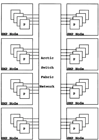
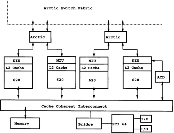
StarT-NG is a joint project between MIT's Computation Structures Group and Motorola to develop a message-passing parallel machine using a Motorola 620 based commercial SMP. The StarT-NG consists of eight SMP sites, each with four proces-sors. (Fig 1-1) These processors are connected by the Switch Fabric Network, a fat tree of 4x4 routers. The network connects to the processors through a Network Interface Unit on each processor's L2 Cache Interface. (Fig 1-2)
The Arctic Switch Fabric Network is a 32 leaf fat tree constructed from 16 circuit boards with 4 Arctics on each board. Figure 1-3 shows the fat tree configuration for an 8 leaf branch of the network. Arctic is a 4x4 200 MB/link/second packet-switched router developed by MIT. Each Arctic has an expanded IEEE standard JTAG interface used for accessing various registers within the chip. These registers are used for configuring the router, collecting statistics and error information, and for testing.
8MP Node 3MP Node Arctic Switch Fabric Network p SNP Node
Figure 1-1: Block diagram of the StarT-NG
Arctic Switch Fabric
Figure 1-2: A StarT-NG Node
ARCTIC
TCLK
JTAG Interface TDO
Figure 1-4: The Arctic Router
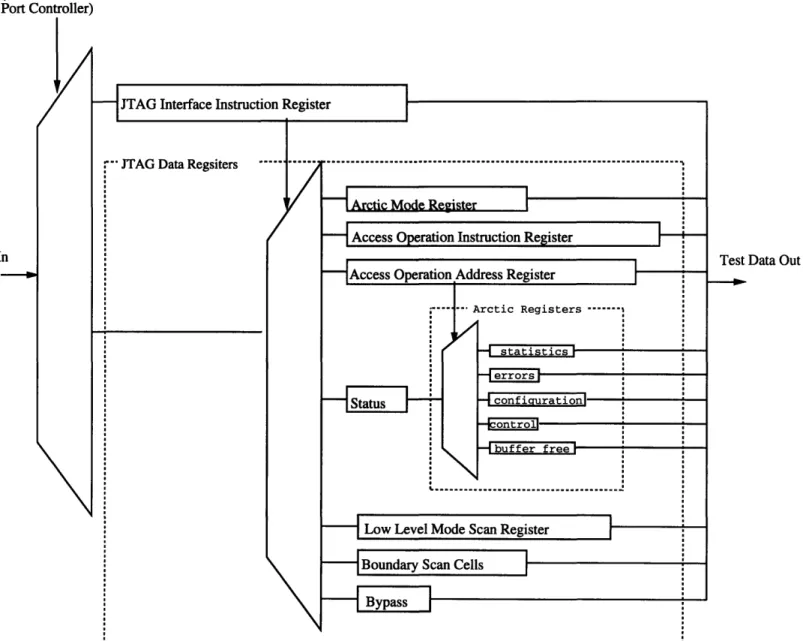
The JTAG interface (Fig 1-4) to an Arctic consists of a clock(tclk), a Test Mode Select (tms) line, a Test Data In (tdi) line, and a Test Data Out (tdo) line. The tms line is used to cycle through a finite state machine, the states of which define whether the JTAG interface is idle or accessing a register. In some of these states the tdi and tdo lines are connected to a selected register within the Arctic and the register's contents can be serially written or read. (Fig 1-5) There are two classes of registers accessible through the JTAG port. First are the JTAG Data registers which are selected using the JTAG Interface Instruction Register. Among the JTAG Data Registers is a Status and Data register. The Data part of this register can be one of a number of Arctic Data Registers. Which Arctic Data Register is accessed by the Data Register is determined by the value in the Access Operation Address Register. The Arctic User's Manual [2] describes in detail how Arctic registers are accessed.
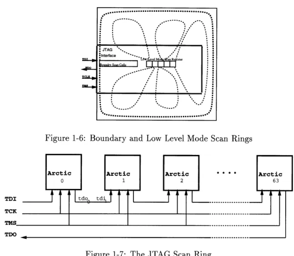
JTAG Data Registers also include two scan cell registers . The Low Level Mode Scan Register connects to a series of six scan rings that can be used to test the Arctic chips. The Boundary Scan Cells register allows bits to be input to or read from each of the Arctic's pins. (Fig 1-6)
(Test Access Port Controller)
-JTAG Interface Instruction Register
:'" JTAG Data Regsiters ..---...--..
S/ Arti Mod Reste
- Access Operation Instruction Register
I|
reAccess Operation Address Register
... .. Arctic Registers ---. -4statistics ! ! - ttsconfigurationl | I "-cnrl I : I buffer free]
I\
S Low Level Mode Scan Register
"" Boundary Scan Cells
Bypass
-.. ... ... ... ... ...
Figure 1-5: The Registers within an Arctic
lata In Test Data Out
Figure 1-6: Boundary and Low Level Mode Scan Rings
Figure 1-7: The JTAG Scan Ring
scan ring allowing all the chips to be controlled together. (Fig 1-7) In the scan ring the same clock and tms signals are sent to all the Arctics, and the tdo line of each Arctic in the ring is connected to the tdi line of the next. In this way registers on all the routers can be accessed though a single JTAG interface to the network. This interface is connected to a JTAG Controller Board (Fig 1-8) which consists of three FIFOs that accept and buffer the tms, tdi, and tdo bits. The Controller Board sits on the ISA bus of a Power PC. The ANCIS system runs on this computer and access
the Controller Board FIFOs using memory mapped writes and reads.
ANCIS itself was designed with several layers of abstraction corresponding to the underlying hardware interfaces. (Fig 1-9) Within the StarT-NG the highest level is a set of C commands that can be called by a script interface written by Motorola. For testing purposes a different script interface was written that allows tests to be input to a single Arctic or to the 4 Arctic network board directly through the JTAG Controller
MS FIFO
IDI FIFO DO FIFO TMS TDI TDOFigure 1-8: The JTAG Controller Board
Board. The next layer of abstraction deals with the somewhat complicated protocol required by Arctic for accessing registers through the JTAG interface. Finally, the lowest abstraction layer masks the protocol required by the JTAG Controller Board.
PC
ISA
script files data files
log files
JTAG Board Device Driver
Chapter 2
ANCIS Design
The basic ANCIS structure consists of three layers of programs. At the highest level a script interface is used for writing test and configuration sequences. This is followed by the Arctic Interface which is a set of read/write register commands used by the script interface and accessed by Motorola's script interface within the StarT-NG. Finally at the lowest level is a set of JTAG board commands used by the Arctic Interface to actually send bits to the network.
2.1
Design Outline
The basic ANCIS structure is shown in figure 1-9. The program layers depicted are:
Script Interface :
Reads testing script files and translates them to Arctic Interface commands.
Arctic Interface :
Translates commands from the Script Interface commands, or those received from the Motorola Script Interface, into bits to be sent to the controller board.
JTAG board low level control :
Runs the controller board. Sends bits from the Arctic Interface and deals with controller board commands and controller board status.
2.2
Script Interface
Script files are used to list a set of Arctic Interface Commands to be run using the command run_script. Within a script command argments can either be listed or replaced with a reference to a separate file. Scripts can output log files, and compare log files to check files. Finally, scripts are made more general by allowing for variables that are replaced by command line arguments. Details are given in section 3.1.
2.3
Arctic Interface
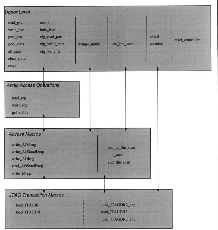
The layering of the Arctic Interface corresponds to that of the Arctic Access Opera-tions, Access Macros, and JTAG Transaction Macros described in the Arctic User's Manual [2]. The design is essentially the same as that described by Mark Nodine [5] for his proto-type Arctic Device Drive Design. However, it allows for the chain of Arctics rather than a single Arctic. It also includes instructions for extest and arcintest.
Upper Level
The upper level of the Arctic Interface consists of the commands accessible to the Script Interface. These include separate reads and writes for each register within Arctic, and resets for the JTAG port, and JTAG controller board. Arctic Registers are listed in figure 1-5.
Each register within Arctic has a different length and format, making separate read/write commands for each necessary. In addition, each read and write can be done on a selected set of Arctics in the scan chain, bypassing the others. Upper Level write commands accept the data to be written directly into the JTAG scan chain. Read commands output whichever bits are returned from the scan chain on the read. Thus it is up to the user to know the data format for the register being accessed.
Upper Level commands also take an argument defining which Arctics in the scan chain are to be operated on. Arctics that are not required for the command are put
into a bypass mode where the one bit bypass register is switched into the scan chain. The data argument given to the Upper Level commands must contain the bits for all of the Arctics being accessed, in scan chain order. However, ANCIS automatically inserts and removes the one bit bypasses. The format of data arguments is discussed in more detail in section 3.2.
Arctic Access Operations
Arctic Access Operations are used to issue reads and writes of the Arctic Data Reg-isters. (Fig 2-1) Reads and writes to Arctic Data registers are two-phase operations.
This is because the Arctic Data Register desired must first be selected by writing the Access Operation Address Register. This connects the Arctic Data Register to the AOS_and_Dreg (Arctic Operation Status and Data Register) path. Next, the opera-tion desired must be written to the Access Operaopera-tion Instrucopera-tion Register. After a read or write has been called in this manner, some time later a status and returned data will appear in the AOS_and_Dreg. The read or write is not valid until a COM-PLETED status is returned. There are however some registers that are guaranteed to be read or written immediately and thus do not return a status. These registers are the port/statistics control register, the system-reset control register, the error counters, and the buffer-free counters. A status check is performed by calling the get_status instruction which repeatedly reads the AOSand_Dreg until a completed status is returned for all Arctics being accessed. The status check is placed at this level because any lower level would need to be passed the location of the status bits within the data chain for each Arctic being accessed, as well as a flag indicating whether status is required for the operation.
Access Macros
The Access Macros package Arctic Access Operations into JTAG Transaction Macros. The Arctic Mode, Access Operation Address, Access Operation Instruction, Status and Data, and Low Level Mode Scan Registers are all accessed by placing a select-register command in the JTAG Instruction Register. (Fig 2-1) This connects the
JTAG Data Registers
S---IArctic Mode Register
Access Operation Address Register
Arctic Data Registers
Status. I- -. --- L ... . % ' .• [" . ..17 ---..5 I
...
r,4UYkYgH....Low Level Mode Scan Register
- Boundary Scan Cells
SBypass
TY A PI t f, YI + t; IR i f
Test Data Out
JTAG Interface Instruction Decode
Figure 2-1: The Arctic JTAG Interface
18 Test Data In Test Test Mode Si
i
I
I
I
nerace nsruc on egser
selected register to the tdo and tdi lines so it can be read or written. Access Macros deal with this process of selecting the correct register to be read or written, and then actually accessing that register.
Lowest Level: JTAG Transaction Macros
All JTAG registers are accessed by cycling through the states in the JTAG TAP controller. (Fig 2-2) The tms line changes these states and the tdi line carries the data to be shifted into the registers in the Shift-DR and Shift-IR states.
This level creates the tms and tdi streams. It inserts bypass instructions into the instruction part of the tdi stream and inserts single bypass bits between the register data arguments. It also pulls out bypass bits while reading back the data and before
returning it.
2.4
Extest, Arcintest, and Low Level Scan
The Extest and Arcintest instructions are used to access the boundary scan rings on the Arctics. The boundary scan register allows bits to be read directly from, or written to, the pins of Arctic. Additionally, it includes 16 extra bits for each input and output port since the links between Arctics run twice as fast as the routers themselves. The scan ring also contains the status control register. (Please see the Arctic Manual for more details.) Extest disconnects the pins from the rest of Arctic so that tests of the board interconnect can be run. Arcintest disconnects Arctic from the pins so tests of the Arctic circuitry can be run.
The Low Level Scan instruction is used to access the manufacturing test rings within Arctic. These are scan cells used for running test vectors generated from the HDL model of the chip. There are 6 manufacturing test rings, each corresponding to one bit in the Low Level Mode Scan Register. Each write to the Low Level Mode Scan Register writes one bit to each manufacturing test ring. Each ring is 525 bits long, and thus to do a scan the Low Level Mode Scan Register must be written 525 times before the system clock is cycled. Similarly, the boundary scan register is 338
bits long and the system clock must not be cycled while the register is being written. Because of this Extest, Arcintest and Low Level Scan use an additional set of JTAG Transaction Macros to allow them to pause in the Pause-DR state rather than the Run-Test-Idle state (which advances the system clock).
Since the Low Level Mode Scan Register and Boundary Scan Cells are JTAG Data Registers instead of Arctic Data Registers, Extest, Arcintest and Low Level Scan do not follow the layers of abstraction used by the rest of the Arctic Interface. Extest and Arcintest both deal directly with the Pause-DR JTAG Transaction Macros. Low Level Scan uses its own set of Access Macros as well as these JTAG Transaction Macros. (Fig 3-2)
2.5
JTAG Board Low Level Control
The JTAG board low level controller receives sets of tdi and tms bits from the Arctic Interface, sends them to the JTAG board, sends "go" commands at the appropriate times, and reads back the tdo data coming out of the board. Detail on how the JTAG controller board works can be found in Professor Moona's paper [4].
The boardsend_bits instruction treats the data it is given as a single set that can be sent to the JTAG board along with a "go" command. The JTAG board repeats the last bit in a set when it is idle and thus each set of bits must end in a pause state. In addition the JTAG board's FIFOs are 4k bytes long so that each set of bits must be less than 4k bytes.
Chapter 3
ANCIS Implementation
ANCIS was implemented in C as a set of library functions. At the top level these are called by Motorola's scripting interface. For testing, these functions are accessible through a testing script interface also implemented in C. At the lowest level ANCIS interacts with a simple device driver for the JTAG Controller Board.
3.1
Scripts
The following section describes the script interface used to test the Arctic chip and 4 Arctic board. Scripts are used to list and run a set of ANCIS commands. The output received when the commands are run can be written to a log file for examination. Moreover, these log files can be checked against compare files containing the correct outputs so that any errors are automatically caught. Scripts are made more general by the use of command line arguments that can replace < arg# > strings within the script file, and the ability to replace ANCIS command arguments with the name of a file containing the correct arguments.
Scripts are run using the command:
runscript<file_name> <argl> <arg2> ....
Tells the Interpreter to run the commands listed in the given filename. Com-mands listed here can be any of the Direct Arctic Interface comCom-mands. These are described in section 3.2.
The arl, arg2, etc. arguments to runscript can be used to replace the text < arg# > within the script with the text given in the argument.
ANCIS commands should be listed within scripts as described here. Each com-mand in a script should be on a separate line followed by a list of the comcom-mand's arguments, also each on separate lines. Alternatively, argument lists can be replaced by the keyword FILENAME followed by the name of a file containing the replaced arguments. Details of each ANCIS command and the arguments they take are given in section 3.2.
For each command given, data must be provided separately for each Arctic in the scan chain. Arctics are labeled by scan chain number from 0 to 63. If data is not provided for an Arctic that Arctic is bypassed while the command is run. Data for individual Arctics should be listed as the keyword ARCTIC followed by an Arctic number on a line by itself immediately preceding the actual data. Data for Arctics should be listed in increasing Arctic number order. For commands that do not take inputs, the Arctics operated on can be defined by listing just the ARCTIC
< Arctic# > lines.
In addition to the ANCIS commands, there are three log commands allowed in a script:
startlog<filename> :
Writes the command's outputs to a log file. If this command hasn't been called outputs are ignored.
endlog :
Must be called sometime after starting a log, and before opening another.
compare_logs <logfile> <comparison file> <results file> :
Can be used when running a test to see if the correct data was received. Writes any discrepancies to the results file.
startlog my.log portstat
$1
statistic ARCTIC 1 ARCTIC 14 ARCTIC 33 readpsc FILENAME leaves.arcs cfgwriteport 2 ARCTIC 7 data ARCTIC 52 data endlogFigure 3-1: A Sample Script File
3.2
Arctic Interface
This section describes the details of the functions used in each layer of the Arctic Interface. All functions are implemented in C. Figure 3-2 gives a block diagram of the functions and their interaction.
The JTAG interface to the Arctic Scan Chain receives data one bit per clock cycle on the tms and tdi lines. Data to be written into a register is given to the ANCIS upper level functions as a set of bits. ANCIS adds bypass bits and padding to be entered on the tdi line while the JTAG controller cycles states. It also creates the
corresponding set of bits to be entered on the tms line.
These sets of bits are passed around ANCIS as data_streams; structs used to abstract the idea of sets of data in which bits need to be inserted, changed, or removed. Data_streams are implemented as a list of integers that contain the bits of the stream and a size variable that keeps track of the stream's overall size. Data_stream structs are accessed through a set of functions for data_stream creation, deletion, and bit or
Figure 3-2: Arctic Interface Functions
byte reads and write.
Upper Level
Upper Level functions are listed below. Upper Level functions are used to access each register within the Arctics. In addition there are reset commands for the JTAG ports and the JTAG controller board. Register data arguments are given to, and returned by the Upper Level as data.streams. These are written as if the Arctic chain only contained those Arctics that are operated on, bypass bits are not included. The int Arctics[] argument defines which Arctics in the scan chain a command is to operate on. Arctic[] is a list of integers the size of the scan chain. Arctics[i] contains a 0 if Arctic i in the scan chain should be bypassed, and a 1 if Arctic i should execute the function.
Upper Level functions include:
void read_psc (struct data_stream *data, int Arctics[]);
Reads the port/statistics control registers for the specified Arctics. inputs: arctics
outputs: data out
void write_pse (struct datastream *data, int Arctics[]);
Writes the give data into the port/statistics control registers for the specified Arctics.
inputs: data
outputs: acknowledgement
void reset (int Arctics[]);
Resets the specified Arctics. Clears the error counters and disables all input and output ports.
inputs: arctics
outputs: acknowledgement void reset_controller ();
Resets the JTAG controller board and all of the Arctics' TAP controllers. inputs: none
void portstat (int port, enum STATS stat, struct data_stream *data,
int clear, int Arctics[]);
Reads the given statistics register for the given port in the specified Arctics. Clears the statistic register after reading if clear is set to 1.
inputs: port, statistic, arctics outputs: data out
void portstats (int port, struct data_stream *data[6], int clear, int Arctics[]);
Reads all the statistics for a given port in the specified Arctics. Clears the statistics read if clear is set to 1.
inputs: port, arctics outputs: data out
void allstats (struct data_stream *data[4][6], int clear, int Arctics[]);
Reads all statistics for all ports in the specified Arctics. Clears the statistics read if clear is set to 1.
inputs: arctics outputs: data out
void clearstats (int Arctics[]);
Clears all the statistics counters on all ports in the specified Arctics. inputs: arctics
outputs: acknowledgement
void errors (struct datastream *data, int clear, int Arctics[]);
Reads the error counters for the specified Arctics. Clears te counters after reading them if clear is set to 1.
inputs: arctics outputs: data out
void bufs free (struct datastream *data, int Arctics);
Reads the buffer free counters for the specified Arctics. inputs: arctics
outputs: data out
void cfgreadport (int port, struct datastream *data[5],
int Arctics[]);
Reads the configuration registers for the given port in the specified Arctics. inputs: port, arctics
outputs: data out
void cfgwriteport (int port, struct datastream *data[5], int Arctics[]);
Writes the configuration registers for the given port in the specified Arctics. inputs: port, data in
void cfgwrite-all (struct datastream *data[5], int Arctics[]);
Writes the configuration registers for all ports in the specified Arctics with the same data.
inputs: data in
outputs: acknowledgement
void change_mode (enum MODES mode, int Arctics[]);
Changes the mode in the given Arctics to mode. Changing to configuration mode requires that all input and output sections of the chip be disabled for 480ns prior to entering configuration mode. It is the user's responsibility to make sure this is done.
inputs: mode, arctics outputs: acknowledgement
void extest (FILE *data_in, FILE *data_out, int size, int Arctics[]);
Runs an extest sequence on the given Arctics using the data in datain and writing the output to dataout.
inputs: sequence size, data in outputs: data out
void arcintest (FILE *data_in, FILE *data_out, int size, int Arctics[]);
Runs an arcintest sequence on the given Arctics using the data in datain and writing the output to dataout.
inputs: sequence size, data in outputs: data out
void dollmscan (FILE *datain, FILE *data_out, int Arctics[]);
Runs a low level scan on the given Arctics using the data in datain and writing the output to dataout.
inputs: data in outputs: data out
Note: extest, arcintest and low level scan use a different set of lower level commands and thus are described in separate sections.
Arctic Access Operations
Arctic Access Operations are used to issue reads and writes to the Arctic Registers. Since these are split phase operations, the getstatus instruction must be called after calling the readreg instruction to retrieve the requested data, or after calling the writereg instruction to confirm the write. However, there are some registers that are
guaranteed to write quickly and do not use the get_status instruction after a write. These are the port/statistics control register, the system-reset control register, the error counters, and the buffer-free counters.
Arctic Access Operation functions include:
void read_reg (enum REGISTERS address, int Arctics[]);
Sets up the register to be read. Actual reading is done by a call to getstatus.
void write-reg (enum REGISTERS address, struct data-stream *ds, int data_len, int Arctics[]);
Writes the data in ds to the given register. The write isn't completed until a call to get_status returns COMPLETED. (unless you are writing one of the fast registers listed above)
int getstatus (struct datastream *ds, int data_len,
int Arctics[], int status?);
Continues to read the AOSandDreg until a COMPLETED or error status is returned by all the Arctics. Returns the status. Setting the status? argument to 0 indicates that the getstatus is being called on one of the fast registers and the status does not need to be checked.
Access Macros
Access Macros are used to package Arctic Access Operations into JTAG Transaction Macros. These select the correct register to be accessed, then do the access.
Access Macro functions include:
void writeAOAreg (enum REGISTERS address, int Arctics[]); Writes the AOAreg with address for each Arctic specified.
void write_AOSandDreg (struct datastream *ds, int data_len,
int Arctics[]);
Writes ds to the AOSandDreg.
void write_AOIreg (enum INSTRS instruction, int Arctics[]); Writes the AOI reg with instruction for each Arctic specified. void read_AOSandDreg (struct data_stream *ds, int Arctics[],
int datalen);
Reads the AOSandDreg into ds.
void writeMreg (short mode, int Arctics[]); Writes the given mode for each Arctic specified.
Lowest level: JTAG Transaction Macros
JTAG Transaction Macros create the tms line bits used to cycle though the JTAG
TAP controller states. They also pad the tdi line so that the desired data is entered in the correct JTAG controller states.
JTAG Transaction Macros include:
void loadJTAGIR (enum INSTRS instr, enum INSTRS alternate, int
Arctics[]);
Loads the JTAG instruction Register with instr, ignores returned bits. The instr argument is a single instruction that is repeated for each Arctic to be operated on. All other Arctics are given the instruction named by alternate. Alternate will be bypass for most instructions and clamp for arcintest and extest instruc-tions.
TAP Controller States: Run-Test-Idle Select DR Scan Select IR Scan Capture IR Shift IR Exit1 IR Update-IR Run Test Idle
void load_JTAGDR (struct datastream *ds, int Arctics[], int data_len);
Loads the JTAG Data Register with ds, puts returned bits into ds. The ds argu-ment does not contain any data for Arctics to be bypassed. Thus load_JTAGDR puts in bypass bits for all bypassed Arctics when sending ds to the Controller Board and removes them again before returning the data received.
TAP Controller States: Run-Test-Idle Select DR Scan Capture DR Shift DR Exit1 DR Update-DR Run Test Idle
func-tions. Extest, Arcintest and Low Level Scan use an additional set of JTAG Transac-tion Macros. These are described in secTransac-tion 3.3.
3.3
Extest, Arcintest, and Low Level Scan
As described in section 2.4 Extest, Arcintest and Low Level Scan are accessed in a different manner then the other registers on the Arctics, and thus use different sets of commands.
Extest, Arcintest, and Low Level Scan Upper Level Commands include:
void extest (FILE *data_in, FILE *data_out, int size, int Arctics[]);
1. Writes the extest instruction to all Arctics specified in Arctics[], writes the clamp instruction to all others.
2. Feeds in the data in the datain file. Size indicates how many sets of extest scans there are. Writes the data returned into the dataout file.
void arcintest (FILE *datain, FILE *data out int size, int Arctics[]);
1. Writes the arcintest instruction to all Arctics specified in Arctics[], writes the clamp instruction to all others.
2. Feeds in the data in the datain file. Size indicates how many sets of arcintest scans there are. Writes the data returned into the dataout file.
void do_llmscan (FILE *data-in, FILE *dataout, int Arctics[]);
Does a complete low level scan (525 cycles) using the data in the file datain and writing the data returned to the file data_out.
Low Level Scan Access Macros
void set_up_llmscan (struct datastream *ds, int arctics[]);
Writes the JTAG Instruction Register and reads the first scan. Writes the data that is returned into ds.
void Ilmscan (struct datastream *ds, int arctics[]);
Cycles the system clock. Reads ds into the scan rings, puts returned data into ds.
void end_llm.scan ();
Extest, Arcintest, and Low Level Scan JTAG Transaction Macros void loadJTAGDR2_beg (struct data_stream *ds, int Arctics[],
int data_length);
Does first scan and ends in the Pause-DR state. Fills in bypass bits before scanning and removes them again before returning data.
TAP controller states: Run Test Idle Select DR Scan Capture DR Shift DR Exitl DR Pause DR
void loadJTAGDR2 (struct data_stream *ds, int Arctics[],
int data_length);
Cycles the system clock then does the next scan. Fills in bypass bits before scanning and removes them again before returning data.
TAP controller states: Pause DR
Exit2-DR Update_DR Run Test Idle Select DR Scan Capture_DR Shift DR Exitl-DR Pause DR void load_JTAGDR2_end ();
Returns the TAP controller to Run-Test-Idle. TAP controller states:
Pause DR Exit2-DR UpdateDR Run Test Idle
3.4
JTAG Board Low Level Control
There are two functions that allow access to the JTAG Controller Board. The first, board_send_bits is used to send a set of accesses to the Controller Board and receive
the data returned by those accesses. The second is used to reset the board.
int board_send_bits (struct data_stream *tdi, struct datastream *tms);
1. Sends the given tms and tdi bits out to the board. Bits must end in a pause state and begin in the state the last instruction left them in.
2. Sends a go instruction to the board.
3. Waits until the board is finished, and reads the data from TDO into the tdi datastream.
int board_reset ();
1. Resets the JTAG board
2. Writes two idle bytes and reads one to fill up the byte left in the serial to parallel converter and the bit left in the tdi buffer.
Chapter 4
ANCIS Testing and Use
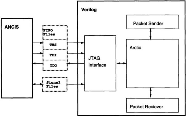
A simplified version of the script interface has been implemented. In addition, the Arctic Interface Commands to read and write the statistics, mode, and configuration register commands have been implemented and debugged. The current system is being tested using a Verilog model of the Arctic chip as shown in Fig. 4-1. The testing setup is somewhat convoluted since Verilog provides no easy way of communicating with other programs while running a simulation. However ANCIS needs ongoing commnication with the chip model since it must know the results of each getstatus instruction before generating its next set of commands.
To allow ANCIS to interface to the Verilog model of Arctic the JTAG controller board functions are simulated by reading and writing to a set of files. There is one file for each of the tms and tdi fifos. ANCIS generates sets of tms and tdi bits and writes them to these files. The data is then read into memories within the Verilog model. Verilog enters the bits in the tms and tdi memories into the Arctic Verilog model using a modified JTAG interface of an Arctic test program written by Richard Davis [3]. Tdo bits returned from the Arctic model are written to another memory, which is written to a file which ANCIS reads after Verilog has completed each stage of the simulation.
Control between ANCIS and Verilog is maintained with another set of files. Once ANCIS has generated a set of tms and tdi bits it increments a counter and indicates the number bytes in the fifo files in a signal file. Verilog continuously reads this file
ANCIS
Figure 4-1: Verilog/ANCIS Interaction
until the counter is increased, at which point it reads the fifo files and begins it's simulation. Meanwhile ANCIS waits for a Verilog signal file to be written. Verilog creates this file when it's simulation is finished, ANCIS erases it again, and goes on to generate the next set of fifo bits.
4.1
Example
Figure 4-2 shows a script file that runs the startup procedure for a single Arctic then reads the port statistic control register to show a read operation. The following section goes over the ANCIS debugging log file for this script to demonstrate how ANCIS works.
Configuring an Arctic involves five steps. First the JTAG controller is initialized using the JTAG reset line. This is done by the JTAG Controller Board when it is reset. Second Arctic itself is reset using the reset command which writes to the system-reset register. Third Arctic is put into configuration mode and the configuration registers are written. Fourth, the mode it changed back to normal mode. Finally, the statistics
reset_controller reset ARCTIC 0 changemode config ARCTIC 0 cfgwrite_all regl ARCTIC 0 Offbdff8 reg2 ARCTIC 0 040f7bfe reg3 ARCTIC 0 00000000 reg4 ARCTIC 0 00000000 reg5 ARCTIC 0 000300ff changemode normal ARCTIC 0 clear-stats ARCTIC 0 writepsc ARCTIC 0 33333 readpsc ARCTIC 0
counters are cleared. This is done by reading the clear statistics registers. In the example the port statistics control register is then written to enable the inputs and outputs.
In the example the ANCIS level that issued each command is indicated by the indentation. Script commands are not shown since they mirror the Upper Level of the Arctic Interface. Arctic Interface Upper Level commands and their arguments are not indented. Arctic Access Operations are indented three spaces, Access Macros are indented six spaces, JTAG Transaction Macros are indented nine spaces, and controller board commands are indented twelve spaces. Commands at each Arctic Interface level are diagramed in figure 3-2. Figure 2-1 diagrams the different registers within Arctic.
The symbol < .... > indicates that lines have been deleted from the example to
make it readable. Most of the commands are only shown through the Arctic Access Operations; read_reg, writereg, and getstatus which are used to access the Arctic Registers. Notice that the the getstatus command is used for reading after the readpsc command and for checking status after writing the configuration registers, but is not required after the write_psc command.
The write_psc command demonstrates how the Arctic Access Operations are bro-ken down into Access Macros which write the sequence of JTAG registers required to access an Arctic Register. The write AOAreg within the readpsc command is used to show how Access Macros are further broken down into a sequence of JTAG Transaction Macros which create the sequence of load JTAGIR and load JTAGDR instructions required to write a JTAG register. Finally the write AOIreg instruction within the read_psc command shows the actually bits written to the board by the JTAG Transaction Macros. It also demonstrates the board go command which sends the bits in the board's FIFOs to Arctic.
Figure 4-3 is the grwaves window of the Verilog simulation after the example has been run showing that the registers within the chip are written correctly.
reset_controller
board_write addr:122 data:2 reset
write reg addr: 341 data:0 < .... >
change_mode config
write Mreg: 0
The controller board is reset by writing to address 122
Arctic is reset by writing its reset reg-ister
The change_mode instruction skips the Arctic Access Operation level and di-rectly issues the writeMreg Access Macro cfgwrite_all Configuratio2 data = configuration
00011111111110111101111111110000
01111111110111101111000000100000
00000000000000000000000000000000
00000000000000000000000000000000
11111111000000001100000000000000
write reg addr: le0 data:00011111111110111101111111110000
< .... >
get status < .... >
write reg addr: get status write reg addr:
< .... > get status
<
....
>
write reg addr:
<
....
>
get status
<
....
>
write reg addr:
get sta....tus
get status
rn is done by writing all 5 registers
Configuration registers require a status check after writing before the write is guaranteed lel data:01111111110111101111000000100000 le2 data:00000000000000000000000000000000 le3 data:00000000000000000000000000000000 le4 data:11111111000000001100000000000000 changemode normal write Mreg : 1 < .... >
clearstats < .... >
writepsc data =
110000000000000000
write reg addr: 200 data:110000000000000000
write AOAreg: 200 < .... >
write AOSandDreg data:110000000000000000 < .... >
write AOIreg instr: 0 < .... >
read psc
read reg: 200
write AOAreg: 200
load JTAGIR instr: 5
load JTAGDR data:0000000001
<
....
>
write AOIreg instr: 1 load JTAGIR instr: 6
Bits Sent To Board TDI
boardwrite addr:120 data:60 boardwrite addr:120 data:0 TMS
boardwrite addr:121 data:83 boardwrite addr:121 data:1 TDI
boardwrite addr:120 data:0 TMS
boardwrite addr:121 data:0
Writing an Arctic Register is done in three stages
First, the Arctic Operation Address Register is written to indicate which Arctic Register is being accessed
Second, the data is written to the Arc-tic Operation Status and Data Regis-ter
Finally, a "write" command is placed in the Arctic Operation Instruction Register
Accessing a JTAG register is done in two stages
First, the JTAG Instruction Regis-ter is written to indicate which JTAG Register is being accessed
Next, the JTAG Data Register is writ-ten with the data
Writing the JTAGIR or JTAGDR reg-isters consists of sending a set of bits for the TDI and TDO lines to the Controller Board, one byte at a time
An additional byte of TDI and TMS bits must be sent to fill the serial to parallel conversion space in the Con-troller Board
Access Op Address Reg
Access Op Instruction Reg
TMS
TDI
control reg ,jtag ireg
config reg
config reg
config reg
config reg
Figure 4-3: Verilog Grwaves Status Window
go command
board_write addr:122 data:0 ---- Please wait for Verilog to
run---board_read: status
board_write addr:122 data:1 boardread: If
board_read: ff board_read: ff load JTAGDR data:10
< .... >
get status
read AOSandDreg load JTAGIR instr: 7 < .... >
load JTAGDR data:000000000000000000
< .... >
psc read = 110000000000000000
The go command tells the controller board to send the bits in it's FIFO's to Arctic
For testing the go command is simu-lated by Verilog
A read of the controller board status tells ANCIS when the board's FIFO's are empty
The Controller Board must be told to stop after each go command.
ANCIS can then read the data re-turned in the Controller Boards TDO FIFO port port port port mregs ~I~a~I~lb7ID f e 0
f f
br
FF8mt
J000 300 F01)C0 ))0C"0)4ff, Cf[-dFfFOOZ8offf-InIO0000ý-10000000n,40f..7f'e-Offbd
Chapter 5
Future Work
Enough of ANCIS has been implemented to demonstrate that it will work, however there are still parts left unwritten. All of the lower level functions to read and write Arctic Registers are in place so the remaining read and write Upper Level functions should be easy to implement. The scan functions (dollmscan, extest and arcintest) have been sketched out, but still need to be fully implemented and tested.
There are several features that could be added to ANCIS as well. Upper Level functions can easily check that the length of the data arguments passed to them, and create an error if it does not match the length of the register to be read or written. The scripting language does not yet contain all the desired features. Currently none of the log file commands, or the commands to substitute in text or files to a script file have been written.
A future version of ANCIS will want to change where the boardgo commands are issued. Currently they are issued after each JTAG Transaction Macro. This is a mistake, at the JTAG Transaction Macro level a boardgo command only needs to be issued after each loadJTAGDR command. Boardgo commands really only need to be issued after each getstatus command or when the Controller Boards FIFO's are filled. However, this would necessitate that ANCIS to keep track of the number of bytes sent to the FIFOs and require that the get_status command has access to the Controller Board to issue the board_go commands. Moreover, as the Controller Board is not yet available, the exact controller board interface has yet to be tested.
Future versions of ANCIS could also keep track of the data in the JTAG In-struction Registers and Arctic Operation InIn-struction Registers for each chip and not rewrite them if the preceding command used the same instruction as the current one. Finally, the current Verilog model only allows testing of single Arctic length scan chains. Longer scan chains have been checked by hand. However, to make sure bypass instructions are issued correctly a new Verilog model with several Arctics in the scan chain needs to be written.
Chapter 6
Conclusion
ANCIS has been architected so that it provides a simple and usable read/write in-terface to registers in the Arctic Switch Fabric Network for testing procedures and the StarT-NG. At the lowest level it interfaces to the JTAG Controller Board using commands to a specified device driver. Moreover, the architecture allows ANCIS to be implemented easily in a clean, modular fashion.
Enough of the ANCIS read, write and reset commands have been written to initialize an Arctic. These commands have been tested on a Verilog HDL model of the chip to demonstrate their successful performance. In addition the basic design of the remaining commands has been laid out to facilitate future implementation.
The implementation work on ANCIS will be continued next semester by another student following the architecture specified in this thesis. The completed ANCIS system will be used in March to test stand alone Arctic chips, and subsequently to set up the Arctic Switch Fabric Network when it is completed.
Bibliography
[1] IEEE Standard Test Access Port and Boundary-Scan Architecture Std 1149.1, 1990.
[2] Andy Boughton and friends. DRAFT Arctic User's Manual.
[3] Richard Davis. Specification File For ARCTIC Tests, January 1994. [4] Rajat Moona. JTAG Controller Board, February 1995.
Appendix A
ANCIS Code
The Appendix contains the code written so far for the ANCIS system. These files are all currently in the /home/jj/elth/ANCIS/code2/ directory. Verilog simulation code is in the /home/prj4/arcticdf/arctic20testelth/ directory.
Arctic files include:
Scripting Language files: scripts.c, scripts.h
Upper Level commands: upperlevel.c, upperJevel.h
Arctic Access Operations: arctic_access_ops.c arctic.accessops.h Access Macros: access_macs.c accessmacs.h
JTAG Transaction Macros: jtag_trans.c jtag_trans.h Controller Board interface: board.c board.h
Verilog simulation interface: sim.c sim.h
A.1
ancis.h
/ *header file for all parts of the ANCIS program and scripts*/
#include <stdio.h> #include <stdlib.h> #define NA 1
/ *number of arctics in the scan chain*/
#define TEST 1 #include "datastream.h" 10 #include "sim.h" #include "board. h" #include "jtagtrans .h" #include "accessmacs .h" #include "arcticaccessops. h" #include "upper_level .h"
A.2
data_stream.h
/ *header file for data_stream abstraction Elth 11/28/95
*/
#include <math.h>
enum bit{ZERO, ONE};
struct data stream
{ 10
int size;
unsigned short *data;
};
/ *data kept in 16 bit chunks, space allocated when the data_stream is created
bits are labled starting at 0*/
struct datastream *create_data_stream(int size);
/* returns an empty data stream with size space in it */ 20
/ *size = number of bits*/
void delete_data_stream(struct data stream *ds);
/
* deletes the given data stream, deallocates memory used */void set_bit(struct data_stream *ds, long bitnumber, enum bit value);
/ *sets the given bit to value */
enum bit get_bit(struct data_stream *ds, long bitnumber);
/ *returns the value of given bit*/ 30
int set_byte(struct data_stream *ds, long start, short byte);
/*adds given byte to data stream begining at start*/
/
*start is the bit number, not the byte number*/int get_byte(struct data_stream *ds, long start, short *byte); /*returns the next byte in the stream. successive get_nextbyte
commands will return sucessive bytes returns 0 if there are no bytes left
returns number of valid bits if a byte is returned*/ 40
int get_ds_length(struct data_stream *ds);
struct datastream *append streams(struct data_stream *dsl, struct data_stream *ds2);
/ *returns a new data stream that consists of dsl followed by ds2
assumes both streams are full*/
50
struct data_stream *parse_tods(int datal, int sizel, int arctics[NA]);
/
*creates a data stream with datal for each specifiedarctic and no data for each bypasses*/
int add_bits(struct data_stream *ds, int num_bits, int start, 60
int bits);
/*add num_bits number of bits to ds starting at start (bit number)
from the number bits*/
/ * for debugging */ 70
void print_stream(struct data_stream *ds); void bin print(int digits, int number);
A.3
data_stream.c
/ * File containing all data stream functionsdata stream.h contains declarations. Elth 11/28/95
*/
/ * data streams are abstractions for the bit streams to be fed into the scan chain. At upper levels they are used to pass around data to be read into, or read out of the arctic
registers, at lower levels they contain control bits as well o0
data streams can be written and read bit by bit, or byte by byte. their correct length must be defined when they are created. Functions are also provided to get a streams length, create and destroy streams, and combine streams.
*/
#include "ancis.h"
20
void bin_print(int digits, int number)
{
int i;
for(i=0; i<digits; i++)
printf("%d", ((number & (1<< i)) >> i));
printf("\n");
I
struct data_stream *create_data_stream(int size)
/
*creates an empty data stream of size size. returns a pointer to it 30empty data streams have O's in all their data bytes*/
{
struct data_stream *ds;
int i;
if((
ds = (struct data_stream *)malloc(sizeof(struct data_stream))) == NULL) printf("uh oh, can't get enough memory \n");
ds->size = size; 40
size = size/16+1;
if(
(ds->data = (short *)calloc(size, sizeof(short))) == NULL) printf("uh oh, can't get enough memory \n");
for(i=0; i<size; i++)
ds->data[i] = 0;
return(ds); 5so
void delete_data_stream(struct datastream *ds)
/
*deletes the given stream, frees up memory*/{
free(ds->data); free(ds);
}
void set bit(struct data_stream *ds, long bit-number, enum bit value) 60
/
*sets the given bit address to the given value*/{
int i, j;
if(bit number >= ds->size)
{
printf("attempt to set bit outside data stream: %d, %d\n",
bit_number, ds->size);
return;
} 70
if (value == ZERO)
ds->data[bitnumber/16] = ds->data[bitnumber/16] & ~(1 << (bit number%16));
else
ds->data[bitnumber/16] = ds->data[bitnumber/16] |
(1 << (bit number%16));
80
enum bit get bit(struct data_stream *ds, long bit_number)
/ *returns bit bit number from data_stream*/
{
return((ds->data[bit_number/16] & (1 << (bit_number%16))) >> (bit_number% 16));
}
int set_byte(struct data_stream *ds, long start, short byte) 90
{
/*adds given byte to data stream begining at start*/
/*start is a bit number, not a byte number*/
/ *if the byte goes over the lenght of the stream,
truncates the number by filling in to the end of the stream*/
/
*returns number of bits set*/int word_num; int offset;
int mask; 100
short new_byte;
/*if byte outside the data_stream*/
if (start > ds->size)
{
ds->size, start);
return(O);
110
/ * find the offset from the begining of a word and the word number withing the stream */
offset = start % 16; word num = start / 16;
/ * if the entire byte falls within one word */
if(offset <= 8)
{
120/
* clear the correct byte within the word */mask = -(255 << offset);
ds->data[word_num]
=
ds->data[word_num] & mask;
/ *splice in the new byte*/byte = byte << offset;
ds->data[word_num] = ds->data[word_num] I byte; return(8);
130
/
*if the byte is spread over two words*/else
{
/ *first word, Isb of byte*/
mask = -(255 << offset);
ds->data[word_num]
= ds->data[word_num] & mask;
new_byte = byte << offset;
ds->data[word_num] = ds->data[wordnum] I newbyte;
/*second word, msb of byte*/ 140
/*if next byte is over the end of the data_stream stop */
/ *check this bound!!!*/
if((word_num+2) *8 > ds->size) return(offset);
mask = -(255 >> (16-offset));
ds->data[word_num+l] = ds->data[word_num+l] & mask;
new_byte = byte >> (16-offset); 150
ds->data[word_num+1] = ds->data[wordnum+l] I new_byte;
return(8);
}
}
int get_byte(struct data_stream *ds, long start, short *byte)
{
/ *returns the 8 bits starting at bit number start as the arg byte
returns number of bits return. If they byte goes over the end
int word_num; int offset;
short mask; short new_byte;
/
*if byte outside the data_stream*/if (start > ds->size)
{
printf("attempt to get byte not in data_stream: %d, %d\n",
ds->size, start); 170
return(O);
}
/ * find the offset from the begining of a word and the word
number withing the stream */ offset = start % 16;
word_num = start / 16;
/ * if the entire byte falls within one word */ 180
if(offset <= 8)
{
/ * mask off the correct byte within the word, and shift it over to the correct position*/
mask = (255 << offset);
*byte = ((ds->data[word_num] & mask) >> offset);
return(8); 190
}
/ *if the byte is spread over two words*/
else
{
/ *first word, Isb of byte*/
mask = (255 << offset);
*byte = (ds->data[wordnum] & mask) >> offset;
/ *second word, msb of byte*/ 200
/ *if next byte is over the end of the data_stream
stop*/
/ *check this bound!!!*/
if((word_num+2) *8 > ds->size) return(offset);
mask = (255 >> (16-offset));
*byte = (*byte 1 210
((ds->data[word_num+1] & mask) << (16-offset)));
return(8);
int get ds_length(struct data_stream *ds)
/ *returns lenght of data stream */
{
return(ds- >size); 220
}
struct data_stream *append_streams(struct data_stream *dsl, struct data_stream *ds2) int size;
int i, j;
struct data stream *newds;
int offset; 230
unsigned short maskl, mask2;
int dsoffset;
/ *create a new data stream*/
size = dsl->size + ds2->size; new ds = create_data_stream(size); / *transfer over data from dsl */
for(i=O; i<= dsl->size/16; i++) 240
new_ds->data[i] = dsl->data[i]; / *transfer over data from ds2*/
offset = dsl->size % 16; maskl = 65535 >> offset; mask2 = 65535 << (16-offset); ds_offset = dsl->size/16;
/ *clear overflow bits from dsl */ 250
new_ds->data[ds_offset] = new_ds->data[ds_offset] & -(65535 << offset); / *for each word in ds2, split it in half at offset, and
add two halfs one at a time*/
for(i=O; i<= ds2-> size /16; i++)
{
/ *first half of ds2 word*/
new_ds->data[ds_offset+i] = new_ds->data[ds_offset+i]
((ds2->data[i] & maskl) << offset); 260
/ *second half of ds2 word*/
new_ds->data[ds_offset+i+1] =
((ds2->data[i] & mask2) >> (16 - offset));
return(new_ds);
void printstream(struct data_stream *ds)
{
/ *print each bit of stream, in binary*/
int i;
for(i=0; i< ds->size; i++)
printf("%d", get bit(ds, i)); printf("\n");
}280
int add_bits(struct data_stream *ds, int num_bits, int start, int bits)
/*add num_bits number of bits to ds starting at start (bit number) from the number bits*/
/ *for now this is cludged using set byte and set bit*/
{
int i; int j;
290
for(i = 0; i<numbits/8; i++)
{
set_byte(ds, i*8,
(((255<<(i*8)) & bits)>> (i*8)));
I
j = (num_bits- (num_bits%8)); for(i=0; i<num_bits%8; i+-+)
set_bit(ds, j+i, ((1<<(j+i)) & bits)>> j+i); 300
struct data_stream *parse_to ds(int datal, int sizel, int arctics[NA])
/
*creates a data stream with datal for each specified arctic and no data for each bypasses*/{
struct data_stream *ds;
int i, j,k; 310
int count =0; int place =0; for(i=0; i<NA; i++)
{
if (arctics[i] == 1) count++;
I
ds = create_data_stream(count*sizel); 320
if (arctics[i] == 1)
{
for(j=O; j<sizel; j++)
{
setbit(ds, place++, ((datal & (l<<j)) >> j ));
330
return(ds);
A.4
scripts.h
int dostartlog(char log_namef); int do_endjog(); int do_read_psc(); int do_writepsc(); int do_reset(); int do_reset_controller(); int do_port_stat(); int do_portstats();int do_all stats();
int do_clear_stats(); 10 int do_errors(); int do_bufs_free(); int do_cfg_read_port(); int do_cfg_write_port(); int do_cfg_write_all(); int do_changemode(); int do_extest(); int do_arcintestO; int do_dollm_scan(); 20
int get_next_line(char data[6][60]);
struct datastream *read_arctic_and_data_lines(int arctics[, int num_bits); int read_arctic_lines(int arctics[);
A.5
scripts.c
/ * Elth Ogston11-16-95
Sample Scripting Lanugage to Interface with ANCIS commands
*/
/ * just now all that's needed is writepsc and readpsc, max arctics = 1*/
#include "ancis .h" #include "scripts. h"
/ *at present this scripting lanuage does NOT 10
provide for $? input commands
deal with FILENAME data replacement files allow for data check files
allow for comment lines starting with a #
It DOES
allow each ANCIS command to be entered read commands and ARCTIC/data inputs
•*/ 20
/ *global variables for these functions, the script file to read from, and the current line number being read */
int line_number = 0; FILE *script;
main(int argc, char *argvy)
{
char lineparses[6][60]; 30
/ * check for the correct number of arguments to the run_script command (i.e. one, the file name) */
if (argc != 2)
{
printf("to run type run_script <script file> \n"); return 1;
}
40
/ *open the script file for reading*/
if ((script = fopen(argv[1], "r")) == NULL)
{
printf("can't open file %s\n", argv[1]); return 1;
}
/ * the main loop of the program goes through the script file lines 50
one at a time, does a big if-then lookup of the command names and calls a do_that_command function. Each do_command function