Design and Construction of High-Temperature, High-Vacuum Tensile Tester for Fusion Reactor Materials
by Nick Schwartz
Submitted to the
Department of Mechanical Engineering
in Partial Fulfillment of the Requirements for the Degree of Bachelor of Science in Mechanical Engineering
at the
Massachusetts Institute of Technology
June 2018
2018 Nick Schwartz. All rights reserved.
The author hereby grants to MIT permission to reproduce and to distribute publicly paper and electronic copies of this thesis document in whole or in part in any medium now known or
hereafter created.
Signature of Author:
Signature redacted
A<fj)
f
Department of Mechanical EngineeringSignature redacted
Mayl1,2018Certified by:
IV Zachary Hartwig
John C. Hardwick sistint Professo of Nuclear Science and Engineering
Signature redacted
Thesis SupervisorMASSACHUSETS NTTTE
OFTECHNOLOGY
SEP 13 2018
LIBRARIES
Professor Rohit Karnik Associate Professor of Mechanical Engineering Undergraduate Officer Accepted by:
MiTLibraries
77 Massachusetts Avenue Cambridge, MA 02139 http://Iibraries.mit.edu/ask
DISCLAIMER NOTICE
Due to the condition of the original material, there are flaws in this reproduction. We have made every effort provide you with the best copy available.
unavoidable possible to
Thank you.
The images contained in this document are of the best quality available.
Design and Construction of High-Temperature, High-Vacuum Tensile Tester for Fusion Reactor Materials
by Nick Schwartz
Submitted to the Department of Mechanical Engineering on May 11, 2018 in Partial Fulfillment of the
Requirements for the Degree of
Bachelor of Science in Mechanical Engineering
ABSTRACT
Fusion energy is a promising carbon-free, limitless source of energy that could contribute to mitigating global climate change. One of the critical challenges in realizing fusion energy is the survival of structural materials in the extreme environment of a fusion device. Specifically, materials that surround the 100 million 'C plasma must survive high temperatures (>500 'C), intense thermal cycling, transient high heat loads, large structural forces during off-normal plasma events, and exposure to high energy neutrons. Neutron exposure leads to high levels of radiation damage, which results in changes to critical material properties such as ductility and strength.
In order to facilitate a better understanding of the effect of radiation on fusion material properties at high temperatures, a novel high-vacuum (<106 torr), high-temperature (<1000 0C),
tensile testing stand for irradiated specimens was designed and constructed. The test stand was designed to perform tensile testing of structural materials that have been irradiated by 12 MeV protons, which emulate the material response to high-energy neutrons produced in a deuterium-tritium burning fusion device. The specimen will then be heated to 500-1000 0C and tensile tested
in high vacuum to eliminate sample oxidation and provide clean measurements. The design and fabrication of the test stand are given in this thesis, and first results from its commissioning are presented.
Thesis Supervisor: Zachary Hartwig
Table of Contents
ABSTRACT 2
1. Overview 6
1.1 Previous Work 7
1.1.1 Tungsten as a Plasma-Facing Material 7
1.1.2 Material Properties of Tungsten Under Fusion Conditions 8
1.2 Objective 8
1.2.1 Research Objectives 8
1.2.2 Design Objectives 8
1.2.3 Description of Tensile Tester 8
1.2.4 Previous High-Temperature Tensile Testing 9
1.3 Functional Requirements of System 9
1.3.1 Temperature Requirement 9
1.3.2 Radiation Damage 9
1.3.3 Vacuum Requirement 10
1.3.4 Output Requirements 10
1.4 Design Methodologies Explored 10
1.4.1 Heating 10
1.4.2 Stress Measurement 11
1.4.3 Strain Measurement 12
1.4.4 Temperature Measurement 13
1.5 Design Methodologies Chosen 13
2. Design of the Test System 13
2.1 Structural Support 15 2.2 Vacuum System 16 2.3 Water-Cooled System 18 2.4 Measurement Tools 18 2.4.1 Stress 18 2.4.2 Strain 19 2.4.3 Temperature 19 2.4.4 Vacuum Measurement 20 2.5 Ergonomic Design 20
4. Conclusion 22
4.1 Review of Progress 23
4.2 Future Work 23
Table of Figures
Figure 1: Section view of ITER [2] 6
Figure 2: Visualization of SPARC Reactor 6
Figure 3. Example of necking in a tensile test 11
Figure 4. Diagram of additional forces from the bellows, felt by the load cell 12 Figure 5. Diagram of vacuum subassembly and connections to tensile tester 14
Figure 6. Vacuum chamber stand assembly 15
Figure 7. Claw-style mount on stand assembly 16
Figure 8. Vacuum chamber, all components 17
Figure 9. Bottom of vacuum chamber, including vacuum gauge 17 Figure 10. Vacuum pumps--roughing scroll pump (bottom) and turbo pump (top) 18 Figure 11. Load cell attached to universal joints on either side 19 Figure 12. Tensile test data: Kapton-coated thermocouple wire 21 Figure 13. Location of slippage: Quick-disconnect and pull-rod 22
1. Overview
Nuclear fusion is the process through which two atoms are fused together, releasing energy. Many private companies, universities, and governmental organizations like ITER (International Thermonuclear Experimental Reactor) are attempting to create reactors that can harness the power of fusion (fig. 1). Some of these organizations even have plans to build fusion power plants. In fact, MIT recently announced plans to build a compact, high-field fusion device, known as SPARC (fig. 2), as an intermediate step to a proposed high-field fusion energy pilot plant, known as ARC [1].
Figure 2: Visualization of SPARC Reactor
The fusion of atoms requires that they be in a plasma. Sustaining plasma presents many technical difficulties. To begin, the temperature needed to sustain plasma is extremely high. For example, the core of the plasma inside ITER must reach 150 million 'C [3]. The materials that are exposed to this plasma will be referred to as the plasma-facing components/materials throughout this paper. Although the containing magnetic fields insulate the plasma-facing surfaces from the
heat in the core of the plasma, some surfaces can still reach temperatures of 500-1000 'C. These materials must survive these temperatures without sacrificing major structural integrity [4] or contaminating the plasma.
In addition to the high temperatures that plasma-facing components must undergo, they are also damaged by high levels of radiation from high energy neutrons, specifically the 14.1 MeV neutrons which are produced by the leading candidate reaction for most fusion concepts: deuterium and tritium [5]. Radiation exposure is measured in displacements per atom (dpa), caused by particles (neutrons, in the case of fusion) elastically displacing material atoms through collision cascades. Radiation exposure to these materials can reach levels as high as 15 dpa per year in plasma-facing components, depending on the material [6]. Additionally, these same neutrons
produce helium gas through transmutation, leading to helium accumulation, which can further complicate the material response.
Radiation damage has been known to change many material properties. For example, hardening [7], embrittlement [8], reduction of thermal conductivity [9], void swelling [10], and an increase in ductile-to-brittle transition temperature (DBTT) [11] are a few of the anticipated effects.
A common technique for quantifying the effects of irradiation on material properties are by tensile tests. Tensile testing can provide information like Young's Modulus, Yield Stress, Ultimate Tensile Strength (UTS), and ductility.
1.1 Previous Work
1.1.1 Tungsten as a Plasma-Facing Material
Tungsten has been established as the material of choice for some the plasma-facing components of ITER. Tungsten has a high threshold for sputtering, a process by which particles from a solid are ejected after being struck by ions, contaminating the plasma. Additionally, it has a high melting point (around 3400 'C), so that the material does not soften and lose structural stability at high temperatures. Finally, it has a very high thermal conductivity, so that heat can quickly be transferred to the coolant from the plasma [12].
Specifically, Tungsten will be used in the divertor, which has the purpose of extracting the heat from the plasma while simultaneously keeping it pure. The divertor must be able to take high heat flux while also being able to withstand high fluxes of fusion neutrons. Additionally, Tungsten will likely be used by a power plant like ARC as a shield in the first wall, the other component of the fusion reactor that is in contact with the plasma. Given the use of Tungsten in critical plasma-facing components, it is extremely important that its mechanical behavior is well understood under high-temperature and radiation exposure [13].
ITER has a relatively low neutron flux, and we will just begin to see the effects of radiation damage in that machine. However, future generations of fusion power plants, like ARC, will begin to see much higher flux due to longer plasma pulses, which will significantly damage divertor and first wall materials.
1.1.2 Material Properties of Tungsten Under Fusion Conditions
A prior study has performed high-temperature tensile testing of tungsten, up to 600 'C. This study was done for the expressed purpose of finding the ultimate tensile strength and strain hardening exponent of Tungsten at elevated temperatures. In fact, Dube et. al. discuss that results from their experiments would be able to better predict the behavior of Tungsten for use in the divertor and first wall of ITER [4]. They found that the UTS and strain hardening exponent for tungsten at 600 'C are 436 MPa and 0.013, respectively. At room temperature, the UTS is 980 MPa and the strain hardening exponent is ~ 0.08 [14]. Moreover, Tungsten is extremely brittle at room temperature, and is more ductile at higher temperatures. However, the specimens that they tested had not been irradiated. Irradiation would add significant damage, affecting its strength and ductility as discussed in Section 1.
1.2 Objective
1.2.1 Research Objectives
Determining how mechanical properties change under irradiation at high temperature can lead to improved design of plasma-facing materials. Additionally, having the ability to quantify the lifetime lengths of plasma-facing components is a critical metric for predicting the economic feasibility of fusion power plants. More specifically, the goal is to measure how changes in temperature and irradiation affect the Yield Strength, UTS, and ductility. Yield strength is important because this information determines when a material will permanently deform. Additionally, UTS can provide insight into the maximum stresses that plasma-facing components can have, while maintaining safe operating conditions. And finally, ductility will shed light on the ability of Tungsten to resist fracture under fusion reactor conditions.
1.2.2 Design Objectives
The design of the test system must incorporate several aspects. This tensile tester must be able to handle radioactive samples from irradiation facilities, like ion accelerators or fission test reactors. More specifically, the initial specimens will be irradiated in a cyclotron by 10-30 MeV proton beams. However, this tester can be generalized to test samples from other irradiation facilities. During the tensile testing, the specimen must also be heated to temperatures comparable to those seen by plasma-facing components. However, to avoid the oxidation of tungsten at high temperatures, and those impurities ruining the test results, the specimen must be contained and heated within a vacuum.
1.2.3 Description of Tensile Tester
The tensile tester is the eXper 2611 from ADMET. This tensile tester has a 48-inch stroke, with a total vertical testing space of 54 inches and is rated to 10 kN. The tensile tester was ordered with a furnace heater that can reach 1150 'C.
1.2.4 Previous High-Temperature Tensile Testing
There is a commercial system for high temperature tensile testing in a vacuum. Gleeble 3800 provides a system that can heat specimen up to 3000 'C through direct resistance heating, and comes with a quenching system for quick cooling. However, as discussed later in section 1.4.1, direct resistance heating is not the best solution for our objectives. Additionally, the Gleeble system is fairly expensive, compared to the cost of building an in-house system suited specifically for our needs [15].
Additionally, several have designed their own retorts for high-temperature tensile testing inside a vacuum. For instance, Jack Taylor designed a retort that could heat specimen to 5400 'F (2982 'C) in a vacuum [16]. However, the method of temperature measurement in the specimen is not suitable for our needs, as explained in section 1.4.4. Additionally, Smith and Guard designed and built a high-temperature vacuum furnace that could heat specimen to 1600 'C [17]. However, this retort does not reach our desired vacuum levels. Finally, Bohn and Murphy designed a vacuum retort that could reach temperatures of 1000 'C, however, this experiment has no method of measuring the temperature of the specimen itself, only the temperature of the heating furnace [18].
1.3 Functional Requirements of System
In order to achieve the research objectives, the tensile tester must emulate conditions similar to those inside a fusion reactor. In order to emulate the high temperatures seen inside of fusion reactors, the specimen must be heated. Additionally, the specimen must be irradiated to emulate the effects of neutron flux through the material. Finally, the must be a high vacuum so that the tensile specimen does not oxidize, something which would compromise the tensile data. 1.3.1 Temperature Requirement
Tungsten has a ductile-brittle-transition temperature (DBTT) higher than room temperature. Therefore, it is generally only used as a structural element for high temperature environments [19]. Because of the change in material properties of tungsten at high temperatures, it is crucial that those temperatures be simulated. The temperature of tungsten within a fusion reactor is expected to range from 500 to 1000 'C [4]. The design of the system is based on a functional requirement of the specimen being tested reaching 1000 'C. However, based on previous high-temperature testing of Tungsten, we can conclude that effects on properties like Ultimate Tensile Strength (UTS), Yield Strength, and ductility will change at lower temperatures. As temperature increases, the UTS and Yield Strength decrease and ductility increases [20].
A decrease in UTS and Yield Strength will cause the material to fail before it normally would at room temperature. Furthermore, a decrease in ductility means that the specimen cannot bear as much strain as it could in room temperature conditions.
1.3.2 Radiation Damage
To emulate the damage from high neutron flux, which can be as high as 5 dpa/year [6] for tungsten as a plasma-facing component, we must first irradiate our samples. Furthermore, we must ensure that the damage to the specimen is uniform. In order to achieve uniform damage, the sample
must be small and thin. The diameter of the proton beam in the accelerator that will irradiate the samples is on the order of magnitude of millimeters. Therefore, our sample will roughly measure 2 mm x 0.5 mm x 0.2 mm. However, the tensile tester can be setup to handle specimens with
varying dimensions. The amount of radiation exposure can be quantified with a sensitive ammeter and knowing the flux of charge particles through the sample, measured in displacements per atom (dpa). As with the temperature requirement, it is important to see how UTS, yield strength, and ductility change. Generally for metals that undergo radiation damage, UTS and yield strength increase, and ductility decreases [21].
1.3.3 Vacuum Requirement
Tungsten is very known to readily oxidize at high temperatures, above 400 'C [21]. As any metal oxidizes, it's material properties begin to change because the composition of the specimen itself changes. Therefore, it is important that the specimen being tested does not oxidize. In order to ensure the validity of the test, oxidation can be minimized by a vacuum or inert gas environment. However, the concern with an inert gas is that it is significantly more difficult to decrease the partial pressure of oxygen down to the levels needed so that the specimen does not oxidize substantially [22]. Therefore, a vacuum environment was chosen for the purpose of this work. The functional requirement for this vacuum is lx 10-6 torr, which is roughly the vacuum requirement in ITER [14].
1.3.4 Output Requirements
There are several state properties that must be measured in order to correctly qualify and quantify the results of the tensile tester. Those properties include the temperature of the specimen, the pressure within the vacuum chamber, the stress on the specimen, and the strain of the specimen.
1.4 Design Methodologies Explored
1.4.1 Heating
There were several options for heating the tensile specimen. Those options include inductive heating, Joule heating, and furnace heating.
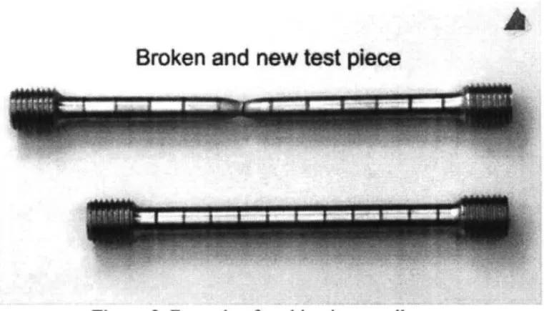
Joule heating or resistive heating occurs when a current is passed through a conducting specimen. Because the specimen has some resistance, the energy produced from current comes in the form of heat. However, as the specimen elongates, it begins to neck during a tensile test, meaning that the middle section has a reduction in cross-sectional area (fig. 3). Thus, the resistance begins to change in a localized manner. Essentially, under enough tension, the specimen will become thinner in the middle, increasing the resistance in that area. Because of this localized change, the temperature would not be consistent throughout the specimen [23]. Instead, the temperature would see an increase in the middle region, where the material is thinner and therefore heats up more quickly
A
Broken and new test piece
Figure 3. Example of necking in a tensile test
Inductive heating is the process by which a conductive material is heated by magnetic induction. An alternating current is passed through an electromagnetic coil that surrounds, but does not touch, the material. Magnetic eddy currents are induced in the material, which heats it up. Here, however, there are issues with localized changes in magnetic reluctance during necking, as described above
Finally, furnace heating describes a system in which a furnace surrounds the specimen. In this case, there is a vacuum chamber around the specimen, so the furnace must be outside the chamber. The furnace convectively heats the walls of the chamber, and the inner walls of the chamber release heat by radiation to heat the specimen. The major benefit of this system is that the specimen is heated uniformly. However, it is a very slow heating process because it is done radiatively. Additionally, heating with a furnace adds additional thermal stresses to the surrounding vacuum components, like the O-rings.
1.4.2 Stress Measurement
The tensile tester in this experiment has a limit of 10 kN (-2250 lbs). However, based off of previous results we predict that the tensile specimens will reach their Ultimate Tensile Strength somewhere between 10 and 100 lbs. This prediction is based off the fact that the UTS is roughly 400 MPa at 600 *C, without prior irradiation [4]. A conservative estimate of 1000 MPa is that
given a cross-sectional area of 0.1 mm2, a force of 22.5 lbf is predicted.
The load cell can either be placed within or outside of the vacuum chamber. Placing it within the chamber presents the problem that it must operate under elevated temperatures. Placing it externally alleviates the concern about increased operating temperature; however, this presents an additional problem of the stress induced by the vacuum pressure. Essentially, the external pressure will push on the bellows, inducing a higher readout on the load cell than what the actual force on the specimen is. Furthermore, the bellows will act like a spring as they expand-the force needed to pull will increase with elongation. Figure 4 below presents a visualization of the two forces on the bellows. Therefore, the range of the load cell should be based off the force vacuum-induced and spring forces of the bellows, in addition to the predicted force needed to break the specimen.
Pressure Force
External Pressure:
760 torr - -r Elongated bello ws,
acting as a spring
Internal Pressure:
10-- torr
Figure 4. Diagram of additional forces from the bellows, felt by the load cell
1.4.3 Strain Measurement
An accurate and repeatable way to measure strain is very important so that the measured tensile properties of the specimen are accurate. There are several approaches to measuring strain within a vacuum chamber, such as a Linear Variable Differential Transformer (LVDT), using a camera to view the specimen, or using lasers to track movement.
One of the difficulties of strain measurement in this case is that it takes place within a vacuum at very high temperature. Due to the vacuum requirement, mechanical access to the specimen must be done through vacuum ports. Furthermore, many electronic components cannot function inside the high-temperature zone of the vacuum chamber, and would need to be placed outside the vacuum. Each of the above options was considered, and the benefits and drawbacks of each are presented.
To begin, using an LVDT or another method of measurement that mechanically measures linear movement has its benefits in a simple working principle and easy repeatability. However, the negatives include the difficulty of keeping the electronics outside the high temperature region, while the sensors themselves are attached to the specimen or the grips. Moreover, the gauge length-the elongation-of the samples is on the order of magnitude of a few millimeters, increasing the difficulty of making accurate measurements.
Using a camera is a non-contact option that is based off the working principle of tracking pixels from frame to frame. Here, there is no worry about the vacuum or high temperature, because the camera can be placed outside the furnace, as long as there is a viewport. However, due to the size of our specimen, the strain will only be a few tenths of an inch until fracture, but the camera must be placed at least 6 inches (the outer diameter of the furnace) away from the specimen. This means that within the images produced, the area of importance is very small compared to the total
frame of view. This concern is problematic because the camera may not have a good enough resolution to capture enough pixels to correctly quantify the elongation of the tensile specimen. Additionally, the specimen will start in a slightly different place each time; therefore, the setup for the camera must be customized for each tensile specimen. Furthermore, there must be a viewing window both in the furnace and the vacuum chamber; these two windows will distort the image.
Finally, the last option is laser extensometry, which illuminates the specimen in 2 places. The interference pattern created is captured by a CCD camera, which is the processed to give information about the strain in the material [24]. This option has the same positives as a camera,
but requires a longer setup to ensure repeatability each time. It also has similar negatives to using a camera, in that camera image is distorted by the two viewing windows.
1.4.4 Temperature Measurement
The temperature of the specimen must be accurately and repeatedly measured. Additionally, the temperature of the specimen must be uniform. Given that the thermal conductivity of Tungsten is 174 W/mK [25] and the small size (a few millimeters, in each dimension) of the specimen, it can be assumed that the temperature in the specimen will be constant. There are two options for temperature measurement. The first is by optical pyrometry and the second by thermocouple feedthrough.
Optical pyrometry offers a non-contact solution in which a laser illuminates the surface of the object, and determines the surface temperature based off the black-body radiation the specimen
gives off. However, this method is limited by the ability to measure through optical ports.
A thermocouple feedthrough into the vacuum chamber offers a versatile solution. A type K thermocouple offers the cheapest, most accurate, and reliable solution [26]. A vacuum feedthrough can have multiple thermocouples, giving the option of measuring the temperature at several different points. The downside to this option includes having to re-attach (by spot-welding) thermocouple(s) to the specimen for every new test.
1.5 Design Methodologies Chosen
Although the design space was fairly large, I was able to narrow it immensely by decisions to the best methodologies discussed in the prior four sections. To begin, furnace heating offered the best solution because of its reliability and ability to evenly heat the tensile specimen. A load cell external to the vacuum chamber offers simplicity and reliability. Although, a final decision on the strain measurement has not been made, I believe that moving forward, using an LVDT is the best option, as it will give the most accurate measurements reliably. Finally, by measuring the temperature of the specimen with thermocouples, we can ensure that there is no gradient in the specimen and have the ability to measure other points of interest.
2. Design of the Test System
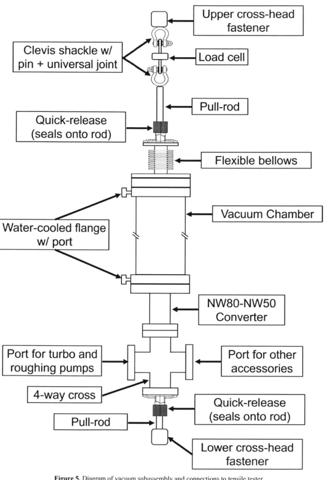
The assembly of the test system consists of several subassemblies. The structural support provides a place for the vacuum chamber to rest while not under tension. The vacuum system is where the tensile specimen is loaded and heated, and consists of the vacuum chamber, various flanges, and the vacuum pumps. The water-cooled system provides cooling to several flanges so that their O-rings do not fail. Finally, the measurement system describes how data is collected while tensile testing. Pictured below is a diagram of the vacuum chamber.
Upper cross-head
fastener
Clevis shackle w/
+-Loadcell
pin
+ universal
joint
+--FPllrod
Quick-release
(seals onto rod)
+--
Flexible bellows
VauuChbr
Water-cooled flange
w/ port
NW80-NW50
Converter
Port for turbo and
Port for other
roughing pumps
accessories
4-way cross
Quick-release
(seals onto rod)
Lower cross-head
fastener
2.1 Structural Support
The vacuum chamber itself must be supported by a mechanism that allows for variable height. The support structure is pictured in Figure 6. It is created from a simple 80/20 aluminum extruded frame and two water-jet cut pieces. The 80/20 allows for flexibility in the y- and z-directions due to its slotted rail profile. The waterjet pieces were designed to allow for flexibility in the x- and y-directions. Thus, no matter where the vacuum chamber is located relative to the frame of the tensile tester, the axis of pulling aligns with the axis of the specimen, alleviating transverse forces in the specimen.
The frame of the tensile tester already had tapped holes that were useful for mounting the 80/20 frame. The actual vacuum chamber itself hangs from the water-jet cut jaws of the support. The inside diameter of the jaws is larger than the outside diameter of the tube, so that the tube can be aligned along the z-axis. The figures below show the final stand assembly.
2.2
Vacuum System
The vacuum components were all chosen/designed based off the functional requirement for the vacuum level and the method of operation, including the installation and removal of samples. To begin, the tube that sits within the heater had to be able to withstand the high temperatures. 304 stainless steel was an excellent choice given its high yield strength at high temperatures. However, this material choice is limited at an intermittent service temperature of
870 'C [27]. Another option is to use Inconel 625, which has operating temperatures as high as 1093 C [28]. However, to demonstrate proof of concept, stainless steel is an easier material to prototype with, considering the ease with which it can be welded.
The ends of the tube needed to be water-cooled such that the O-rings that sealed the vacuum would not fail. The Viton O-Rings from MDC are rated to 150 'C. MDC supplied a thin, water-cooled flange that could be welded on to a 3-inch tube. Additionally, flexible bellows were welded on to the top of the vacuum assembly so that the pull-rods could pull the specimen, but not the stationary vacuum chamber. The Quick-Disconnect provides a vacuum seal both on the opposing flange, and the %/" pull rod. The 4-way cross on the bottom provides ports for a thermocouple feed and the vacuum pump.
To reach a pressure of 10-6 torr, both a roughing pump and turbo pump are necessary. For the purposes of a proof of concept demonstration, a scroll pump and turbo pump were used. Attached to the other end of the 4-way cross is a vacuum gauge. The images below display the various components of the vacuum assembly.
Figure 10. Vacuum pumps-roughing scroll pump (bottom) and turbo pump (top)
2.3 Water-Cooled System
The water-cooled flanges are important so that the outside of the vacuum chamber is not significantly impacted by the heat from the furnace. If the temperature of the seals on the vacuum chamber is too high, those vacuum seals will fail. Thus, the water-cooled flanges offer the ability to absorb much of the heat coming from the furnace. This protects sensitive electronics that are on the outside of the vacuum chamber.
2.4 Measurement Tools
The precise state measurement of the specimen is very important for quantifying results. There are four measurements that are important to the design of the system: stress, strain, temperature, and internal pressure inside the vacuum chamber. Stress and strain are actually calculated based off geometry; pull force and length of the specimen is actually what is measured. 2.4.1 Stress
The pull force is measured by an Omega strain gauge. This strain gauge can measure pull forces up to 250 lbs with an accuracy of +/-15%. It is important that the strain gauge be supported on either side by a universal joint. These joints play an important role if the tensile force is not aligned with the sample axis. Essentially, if the strain gauge is off axis in any direction, the universal joints can correct for this error, and will align the strain gauge with the direction of pull as soon as tension is applied. The image below displays the load cell and universal joints.
There are several issues with force measurement, due to the load cell being placed outside the vacuum chamber. The bellows account for two forces that the strain gauge reads, in addition to the load felt by the specimen. Because the pressure outside the vacuum chamber is higher than the internal pressure, there is a constant force that compresses the bellows, which is felt as tension by the load cell. Additionally, the bellows act as a spring, in which the force increases with elongation. These two forces can be accounted for by calibration measurements. With no specimen installed, the pressure force can be determined by the difference in measured forces-first at atmospheric internal pressure with the bellows under no tension, and then pumping down to a pressure of 10-6 torr. Obtaining a profile for the spring force of the bellows can be done simply by extending the bellows from its equilibrium length (2.0 inches) to its extended length (2.2 inches). Alternatively, MDC offers that the spring rate is 119.02 20%; using Hooke's law, an approximate load profile can be determined using this information.
2.4.2 Strain
We have yet to determine an exact solution to measuring strain. However, based on the information presented in section 1.4.3 using LVDT(s) is the best path moving forward. A possible solution could look like the strain measurement system presented by Taylor in his high-temperature vacuum furnace for tensile testing [16]. This solution would have the electronic components of the LVDT outside of the vacuum chamber, so that they are not exposed to the heat from the furnace. The moving shafts of the LVDT would be fed through a port into the vacuum, and attached to something, like the grips, that has enough stiffness as to not significantly affect the elongation measurement of the specimen.
2.4.3 Temperature
The decision to use a thermocouple feedthrough is very beneficial in terms of versatility. We are able to measure the temperature of several points in the system simultaneously. For now,
the system includes a thermocouple feedthrough with four thermocouples. We measure the temperature of the specimen in two places: on both grip sections of the specimen, so that the spot weld does not interfere with the material properties. Additionally, we measure the temperature of the vacuum chamber in two places: on the hot side of the water-cooled flange, and on the cool
side. If the cool side of the flange reaches above the temperature rating of the Viton O-Ring, we can signal to shut down the furnace, so that the vacuum is not compromised.
2.4.4 Vacuum Measurement
Replicating the conditions inside a fusion reactor are important for this experimental setup, especially the vacuum. A vacuum gauge at the attachment for the vacuum roughing pump reports the vacuum level. Again, if the vacuum is compromised, we can sense this and shutdown the
system.
2.5
Ergonomic Design
The design of the system also took human interaction into account. Installing and removing samples from the tensile tester are both important processes that must be done repeatedly and fairly easily.
The first design choice was which direction the sample would be removed and replaced; the options were through the bottom or through the top of the vacuum chamber. Removing through the top was preferable because the sample would be closer to shoulder height on most people, so that the user would not need to kneel down.
The process then to replace a specimen is the following: First, turn off the vacuum pumps and heater, and let the system cool down and vacuum equilibrate with the atmosphere. At this point, turn off the water to the system and open the clamshell heater, moving it to the side. Remove the clamps from the top water-cooled vacuum flange and undo the quick release flange that is sealed onto the bottom %" rod and unscrew the rod from the grounding connection. Now move the crosshead up until the gripper and specimen are accessible. If the specimen was tested until the break point, one will have to extract the pull rod and specimen manually from the bottom. Finally, one can place a new specimen in the grippers, with the bottom rod hanging from the specimen. The weight of the rod is not enough to stress the specimen past yielding, so the cross head can then be lowered, the bottom pull rod screwed into place and sealed, and the top water-cooled flange clamped back down.
Essentially, there are two detachment points in the vacuum: the bottom quick-release flange that seals on the pull-rod and the top water-cooled flange. By releasing these two seals, and pulling up the cross-head, one can remove the used tensile specimen and install a new one.
3. Initial Characterization of the System
Although high-temperature tensile tests with irradiated specimens was not achieved due to time constraints, proof of concept was demonstrated in several aspects of the design. To begin, we were able to achieve vacuum (5 x 10⁻⁶ torr) with a specimen inside the tensile tester. We expect that
to achieve even better vacuum after cleaning the vacuum system and pre-baking with the heater. The vacuum environment immensely diminishes the effect of oxidation as the specimen is heated. Furthermore, we were successful in collecting tensile data on a test specimen inside the vacuum chamber. Specifically, a strand of Kapton-coated thermocouple wire was attached to the pull rods, and tested until breaking. This wire had a diameter of roughly 1 mm, and a gauge length of-35 mm. Figure 12 shows the force vs elongation. There were auxiliary forces felt by the load cell, in addition to the tensile load on the wire. The first was the spring force of the bellows. Matching a best-fit line to this section, the measured spring constant is 99.2 lbs/in which is within the prescribed range (119.02 lbs/in 20%) given by MDC. Additionally, the pull rod actually began to slip, because the static force of friction from the quick-disconnect O-ring (fig. 13) was not large enough.
Not only were we able to achieve a vacuum, but we also found success in initial characterization of the tensile tester. The system works as predicted-it can measure the tensile load on a specimen in a vacuum. Improvements to the current system are discussed in the following section. 60 50 -Specimen Breaks 40 CD
Slipping Friction Force
30 from O-ring on Pull-Rod 0 IL 20-10 Spring-like Elongation of Bellows 0 0 0.2 0.4 0.6 0.8 1 Elongation (in)
O-Ring and pull-ro ?JWOm~t
Because the pull rod connected to the top cross-head slips, the required vacuum levels are not possible due to leaks through this joint. Therefore, we were not able to run a tensile test under vacuum. Due to the fact that we do not yet have a reliable method to measure the actual elongation ofjust the specimen itself, it is not possible to calculate strain.
4. Conclusion
Conventional tensile tests do not adequately describe the behavior of some fusion materials, like Tungsten, which will operate at elevated temperatures in the presence of radiation. Therefore, it was necessary to design and construct a tensile tester that could perform tests of irradiated samples at high temperatures. It was important, additionally, that the testing be done inside a vacuum chamber, so that the Tungsten does not oxidize.
At elevated temperatures, the yield strength and UTS decrease, but the ductility increases. However, samples that have been irradiated have increased yield strength and UTS, but decreased ductility. The combination of high temperatures and radiation damage leads to changes in the mechanical properties of plasma-facing materials. This tensile tester was constructed for the purpose of quantifying these changes.
The tensile tester was divided into several subassemblies-supporting structure, vacuum components, a water-cooled system, and data collection. We were able to achieve a tensile test under vacuum.
4.1 Review of Progress
This semester, I was able to design and construct a system that could demonstrate proof-of-concept for tensile testing of samples under a vacuum. After the implementation of the suggested improvements in the following section, and the arrival of several key components-the furnace heater and water-cooled flanges, for example-I am confident that this tensile tester will be able to perform high-temperature tensile tests on irradiated samples. These tests will lead to a better understand of how plasma-facing materials that have been damaged by high levels of radiation behave at high temperatures. This knowledge can lead to a better design for
plasma-facing components in future fusion reactors.
4.2
Future Work
There are several components that have not yet been finished, that are needed to provide proof-of-concept for tensile tests of irradiated samples at high temperature. The first is that there is not yet a method designed to determine strain. A system of LVDT's with the electronics on the outside of the vacuum chamber, and the movable parts on the inside would accurately and reliably measure strain. Furthermore, once the tensile tester has been completed, the next step is to then design tensile specimen, grippers, and proceed to irradiate them in a cyclotron and perform tensile tests at high temperatures. Additionally, there is slippage between the top quick-disconnect and the pull-rod, mentioned in the prior section. To alleviate this issue, I suggest a pull rod that is actually welded to a flange. There are additional ergonomic issues with regards to installing the numerous threaded parts
Future improvements that could improve the capabilities of the system using an Inconel
625 tube as a vacuum chamber would surpass the performance of a stainless steel tube, due to Inconel's high temperature rating and strength. For all threaded components, I recommend that the thread on the bottom be a left-hand thread. This way, one can more easily tighten or loosen a specific component.
Bibliography
[1] Sorbom, B. N., Ball, J., Palmer, T. R., Mangiarotti, F. J., Sierchio, J. M., Bonoli, P., Kasten, C., Sutherland, D. A., Barnard, H. S., Haakonsen, C. B., Goh, J., Sung, C., and Whyte, D. G., 2015, "ARC: A Compact, High-Field, Fusion Nuclear Science Facility and Demonstration Power Plant with Demountable Magnets," Fusion Eng. Des., 100, pp.
378-405.
[2] ITER, 2017, "Technical Photos" [Online]. Available: https://www.iter.org/album/Media/7
-Technical.
[3] ITER, "Plasma Heating" [Online]. Available: https://www.iter.org/sci/plasmaheating. [4] Dube, Charu Lata, et al., 2014, "High Temperature Tensile Properties of Tungsten,"
Icons-2014, (February).
[5] Kikuchi, M., Lackner, K., and Quang, M., 2012, "Fusion Physics," Iaea, pp. 24-26.
[6] Gilbert, M. R., Dudarev, S. L., Zheng, S., Packer, L. W., and Sublet, J. C., 2012, "An Integrated Model for Materials in a Fusion Power Plant: Transmutation, Gas Production, and Helium Embrittlement under Neutron Irradiation," Nucl. Fusion, 52(8).
[7] Hu, X., Koyanagi, T., Fukuda, M., Kumar, N. A. P. K., Snead, L. L., Wirth, B. D., and Katoh, Y., 2016, "Irradiation Hardening of Pure Tungsten Exposed to Neutron Irradiation," J. Nucl. Mater., 480, pp. 235-243.
[8] Marian, J., Becquart, C. S., Domain, C., Nordlund, K., Sand, A. E., Snead, L. L., and Suzudo, T., 2017, "Recent Advances in Modeling and Simulation of the Exposure and Response of Tungsten to Fusion Energy Conditions."
[9] Fujitsuka, M., Tsuchiya, B., Mutoh, I., Tanabe, T., and Shikama, T., 2000, "Effect of Neutron Irradiation on Thermal Diffusivity of Tungsten-rhenium Alloys," J. Nucl. Mater., 283-287, pp. 1148-1151.
[10] Moteff, J., Sikka, V. K., and Jang, H., 1975, "The Influence of Neutron Irradiation Temperature on the Void Characteristics of BCC Metals and Alloys," Consult. Symp. "the Phys. Irradiat. Prod. Voids", pp. 181-187.
[11] Ueda, Y., Schmid, K., Balden, M., Coenen, J. W., Loewenhoff, T., Ito, A., Hasegawa, A., Hardie, C., Porton, M., and Gilbert, M., 2017, "Baseline High Heat Flux and Plasma facing Materials for Fusion," Nucl. Fusion, 57(9).
[12] Causet, R. A., and Venhaus, T. J., 2001, "The Use of Tungsten in Fusion Reactors: A Review of the Hydrogen Retention and Migration Properties," Phys. Scr., T94(1), p. 9. [13] Rieth, M., Dudarev, S. L., de Vicente, S. M. G., Aktaa, J., Ahlgren, T., Antusch, S.,
Armstrong, D. E. J., Balden, M., Baluc, N., Barthe, M.-F., Basuki, W. W., Battabyal, M., Becquart, C. S., Blagoeva, D., Boldyryeva, H., Brinkmann, J., Celino, M., Ciupinski, L., Correia, J. B., Backer, A. De, Domain, C., Gaganidze, E., Garcia-Rosales, C., Gibson, J., Gilbert, M. R., Giusepponi, S., Gludovatz, B., Greuner, H., Heinola, K., Hschen, T., Hoffmann, A., Holstein, N., Koch, F., Krauss, W., Li, H., Lindig, S., Linke, J., Linsmeier, C., L6pez-Ruiz, P., Maier, H., Matejicek, J., Mishra, T. P., Muhammed, M., Mufioz, A., Muzyk, M., Nordlund, K., Nguyen-Manh, D., Opschoor, J., Ordis, N., Palacios, T., Pintsuk, G., Pippan, R., Reiser, J., Riesch, J., Roberts, S. G., Romaner, L., Rosiniski, M., Sanchez, M., Schulmeyer, W., Traxler, H., Urefia, A., van der Laan, J. G., Veleva, L., Wahlberg, S., Walter, M., Weber, T., Weitkamp, T., Wurster, S., Yar, M. A., You, J. H., and Zivelonghi, A., 2013, "Recent Progress in Research on Tungsten Materials for Nuclear Fusion Applications in Europe," J. Nucl. Mater., 432(1), pp. 482-500.
[14] Paez, P. L., Iyengar, S., Noah, E., and Melin, S., 2011, "Fatigue Properties of Tungsten Heavy Alloys."
[15] Gleeble, "Gleeble 3800-GTC."
[16] Taylor, J. L., 1963, "Apparatus for Tensile Testing to 5400'F in Vacuum," Rev. Sci. Instrum., 34(5), pp. 500-504.
[17] Smith, E. A., and Guard, R. W., 1956, "High-Temperature Vacuum Furnace for Tensile Testing," Rev. Sci. Instrum., 27(6), pp. 386-387.
[18] Bohn, J. R., and Murphy, G., 1960, "A High-Temperature Vacuum Extensometer."
[19] Stephens, J. R., 1972, "REVIEW OF DEFORMATION BEHAVIOR OF TUNGSTEN AT TEMPERATURES LESS THAN 0. 2 ABSOLUTE MELTING TEMPERATURE," NASA TM X-2482, (January 1972).
[20] Schmidt, F. F., and Ogden, H. R., 1963, The Engineering Properties of Tungsten and
Tungsten Alloys, Columbus, OH.
[21] Gadhave, P. K., Dighe, P. M., and Kalhapure, M. G., 2013, "Effect of Radiation on the Mechanical Properties of Materials," III, pp. 9-11.
[22] Danielson, P., "Why Create a Vacuum?," Normandale Community Coll., (1), pp. 1-6. [23] ITER, "ITER Vacuum System."
[24] GmbH, F. 0., "Working Principle: Laser-Doppler-Extensometer" [Online]. Available: http://www.foe.de/en/products/lde/principle.html.
[25] 2011, "Properties Table of Stainless Steel, Metals and Other Conductive Materials," TIBTECH Innov.
[26] THERMOCOUPLEINFO.COM, 2011, "Thermocouple." [27] "High Temperature Properties," Stainl. Steel Inf. Cent.