HAL Id: ensl-00268348
https://hal-ens-lyon.archives-ouvertes.fr/ensl-00268348v3
Submitted on 11 Sep 2008
HAL is a multi-disciplinary open access
archive for the deposit and dissemination of
sci-entific research documents, whether they are
pub-lished or not. The documents may come from
teaching and research institutions in France or
abroad, or from public or private research centers.
L’archive ouverte pluridisciplinaire HAL, est
destinée au dépôt et à la diffusion de documents
scientifiques de niveau recherche, publiés ou non,
émanant des établissements d’enseignement et de
recherche français ou étrangers, des laboratoires
publics ou privés.
An FPGA-specific Approach to Floating-Point
Accumulation and Sum-of-Products
Florent de Dinechin, Bogdan Pasca, Octavian Creţ, Radu Tudoran
To cite this version:
Florent de Dinechin, Bogdan Pasca, Octavian Creţ, Radu Tudoran. An FPGA-specific Approach
to Floating-Point Accumulation and Sum-of-Products. Field-Programmable Technology, Dec 2008,
Taipei, Taiwan. �ensl-00268348v3�
AN FPGA-SPECIFIC APPROACH
TO FLOATING-POINT ACCUMULATION AND SUM-OF-PRODUCTS
LIP RESEARCH REPORT RR2008-22
Florent de Dinechin, Bogdan Pasca
∗LIP (CNRS/INRIA/ENS-Lyon/UCBL)
´
Ecole Normale Sup´erieure de Lyon
Universit´e de Lyon
[email protected]
Octavian Cret¸, Radu Tudoran
Computer Science Department
Technical University of Cluj-Napoca
[email protected]
ABSTRACT
This article studies two common situations where the flex-ibility of FPGAs allows one to design application-specific floating-point operators which are more efficient and more accurate than those offered by processors and GPUs. First, for applications involving the addition of a large number of floating-point values, an ad-hoc accumulator is proposed. By tailoring its parameters to the numerical requirements of the application, it can be made arbitrarily accurate, at an area cost comparable for most applications to that of a standard floating-point adder, and at a higher frequency. The sec-ond example is the sum-of-product operation, which is the building block of matrix computations. A novel architec-ture is proposed that feeds the previous accumulator out of a floating-point multiplier without its rounding logic, again improving both area and accuracy. These architectures are implemented within the FloPoCo generator, freely available under the GPL.
1. INTRODUCTION
Most general-purpose processors have included floating-point (FP) units since the late 80s, following the IEEE-754 standard. The feasibility of FP on FPGA was studied long before it became a practical possibility [16, 10, 12]. As soon as the sizes of FPGAs made it possible, many libraries of floating-point operators were published (see [1, 9, 11, 15] among other). FPGAs could soon provide more FP comput-ing power than a processor in scomput-ingle precision [11, 15], then in double-precision [17, 5, 4]. Here single precision (SP) is the standard 32-bit format consisting of a sign bit, 8 bits of exponent and 23 bits of significand (or mantissa), while double-precision (DP) is the standard 64-bit format with 11
∗This work was partly supported by the XtremeData university
pro-gramme, the ANR EVAFlo project and the Egide Brˆancus¸i programme 14914RL.
bits of exponent and 52 significand bits. Since then, FPGAs have increasingly been used to accelerate scientific, finan-cial and other FP-based computations. This acceleration is essentially due to massive parallelism: Basic FP operators in an FPGA are typically slower than their processor coun-terparts by one order of magnitude.
Most of the aforementionned applications are very close, from the arithmetic point of view, to their software imple-mentations. They use the same basic operators, although the internal architecture of the operators may be highly opti-mised for FPGAs [13]. Most published FP libraries are fully parameterisable in significand length and exponent length, but applications that exploit this flexibility are rare [15, 17]. The FloPoCo project1 studies how the flexibility of the
FPGA target can be better exploited in the floating-point realm. In particular, it looks for operators which are radi-cally different from those present in microprocessors. In the present article, such operators are presented for the ubiqui-tous operation of floating-point accumulation, and applied to sums of products.
All the results in this article are obtained for Virtex4, speedgrade -12, using ISE9.1, and should be reproducible using Xilinx WebPack and FloPoCo, both available at no cost. Very similar results have been obtained for Altera Stratix II. FloPoCo produces portable VHDL, and is de-signed with the goal of automatic fine-tuning the architec-tural parameters to the target hardware and frequency.
2. FLOATING-POINT ACCUMULATION Summing many independent terms is a very common opera-tion. Scalar product, matrix-vector and matrix-matrix prod-ucts are defined as sums of prodprod-ucts. Numerical integration usually consists in adding many elementary contributions.
accumulated value register input (summand)
Fig. 1. Iterative accumulator
Monte-Carlo simulations also involve sums of many inde-pendent terms. Many other applications involve accumula-tions of floating-point numbers, and some related work will be surveyed in section 6.
If the number of summands is small and constant, one may build trees of adders, but to accomodate the general case, it is necessary to design an iterative accumulator, illus-trated by Figure 1.
It is a common situation that the error due to the com-putation of one summand is independent of the other sum-mands and of the sum, while the error due to the summation grows with the number of terms to sum. This happens in integration and sum of products, for instance. In this case, it makes sense to have more accuracy in the accumulation than in the summands.
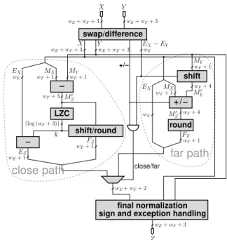
A first idea is to use a standard FP adder, possibly with a larger significand than the summands. The problem is that FP adders have long latencies: typically l = 3 cycles in a processor, up to tens of cycles in an FPGA (see Table 1). This is explained by the complexity of their architecture, il-lustrated on Figure 2.
This long latency means that an accumulator based on an FP adder will either add one number every l cycle, or com-pute l independent sub-sums which then have to be added together somehow. This will add to the complexity and cost of the application, unless at least l accumulation can be inter-leaved, which is the case of large matrix operations [18, 2].
In addition, an accumulator built out of a floating-point adder is inefficient, because the significand of the accumu-lator has to be shifted, sometimes twice (first to align both operands and then to normalise the result, see Figure 2). These shifts are in the critical path of the loop of Figure 1.
In this paper, we suggest to build an accumulator of floating-point numbers which is tailored to the numerics of each application in order to ensure that 1/ its significand never needs to be shifted, 2/ it never overflows and 3/ it eventually provides a result that is as accurate as the ap-plication requires. We also show that it can be clocked to any frequency that the FPGA supports. We show that, for many application, the determination of operator parameters ensuring the required accuracy is easy, and that the area can be much smaller for a better overall accuracy. Finally, we combine the proposed accumulator with a modified, error-less FP multiplier to obtain an accurate application-specific dot-product operator.
sign and exception handling
X X Y EX− EY Y MY MY MX M0 Z EX FZ k EZ EX FZ M0 Z MX M0 Y Z wE+ wF+ 3 wE+ wF+ 3 wE+ wF+ 3 wE+ wF+ 3 wF+ 1 wF+ 1 wE wF+ 3 dlog (wF+ 3)e wE+ 1 wF+ 1 wF+ 1 wE wF+ 4 wF+ 1 wF+ 4 wF+ 1 wE wE+ wF+ 2 wE+ wF+ 3 close/far +/– final normalization LZC shift/round round shift / swap/difference
far path
close path
Fig. 2. A typical floating-point adder (wE and wF are
re-spectively the exponent and significand sizes)
3. A FAST AND ACCURATE ACCUMULATOR This section presents the architecture of the proposed accu-mulator. Section 3.2 will discuss the determination of its many parameters in an application-specific way.
3.1. Overall architecture
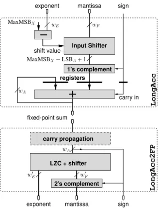
The proposed accumulator architecture, depicted on Fig-ure 3, removes all the shifts from the critical path of the loop by keeping the current sum as a large fixed-point num-ber. Figure 4 illustrates the accumulation of several floating-point numbers (represented by their significands shifted by their exponent) into such an accumulator.
There is still a loop, but it is now a fixed-point addi-tion for which current FPGAs are highly efficient. Specifi-cally, the loop involves only the most local routing, and the dedicated carry logic of current FPGAs provides good per-formance up to 64-bits. For instance, a Virtex4 with speed grade −12 runs such an accumulator at more than 220MHz, while consuming only 64 CLBs. Section 3.3 will show how to reach even larger frequencies and/or accumulator sizes.
The shifters now only concern the summand (see Fig-ure 3), and, being combinatorial, can be pipelined as deep as required by the target frequency.
As seen on Figure 3, the accumulator stores a two’s com-plement number while the summands use a sign/magnitude representation, and thus need to be converted to two’s com-plement. This can be performed without carry propagation:
LongAcc2FP LongAcc wA shift value mantissa carry in MaxMSBX−LSBA+ 1 MaxMSBX exponent wE wF sign mantissa sign exponent fixed-point sum registers w0 F wA w0 E carry propagation LZC + shifter Input Shifter 1’s complement 2’s complement
Fig. 3. The proposed accumulator (top) and post-normalisation unit (bottom). Only the registers on the ac-cumulator itself are shown. The rest of the design is combi-natorial and can be pipelined arbitrarily.
0 0 0 0 0 0 0 0 0 0 0 0 0 0 0 0 0 0 0 0 0 0 0 0 0 0 0 0 0 0 0 0 0 0 0 0 1 1 1 1 0 0 0 1 1 1 1 1 1 1 1 1 1 1 1 1 1 1 1 1 0 0 1 1 10 0 11 10 1 10 1 0 0 0 0 11 1 1 1 wA = MSBA− LSBA+ 1 Accumulator wF+ 1 LSBA= −12 MaxMSBX= 8 MSBA= 16 fixed point Summands (shifted mantissas)
Fig. 4. Accumulation of floating-point numbers into a large fixed-point accumulator
if the input is negative, it is first complemented (fully in par-allel), then a 1 is added as carry in to the accumulator. All this is out of the loop’s critical path, too.
3.2. Parameterisation of the accumulator
Let us now introduce, with the help of Figure 4, the param-eters of this architecture.
• wE and wF are the exponent and significand size of
the summands
• The weight MSBAof the most-significant bit (MSB)
of the accumulator has to be larger than the maximal expected result, which will ensure that no overflow ever occurs.
• The weight LSBA of its least-significant bit can be
arbitrarily low, and will determine the final accuracy as Section 4 will show.
• For simplicity we note wA = MSBA − LSBA the
width of the accumulator.
• MaxMSBX is the maximum expected weight of the
MSB of a summand. MaxMSBX may be equal to
MSBA, but very often one is able to tell that each
summand is much smaller in magnitude than the final sum. In this case, providing MaxMSBX < MSBA
will save hardware in the input shifter.
The main claim of the present article is the following: For most applications accelerated using an FPGA, values of MaxMSBX, MSBA and LSBA can be determined a priori,
using a rough error analysis or software profiling, that will lead to an accumulator smaller and more accurate than the one based on an FP adder. This claim will be justified in section 4.
This claim sums up the essence of the advantage of FP-GAs over the fixed FP units available in processors, GPUs or dedicated floating-point accelerators: we advocate an accu-mulator specifically tailored for the application to be accel-erated, something that would not be possible or economical in an FPU.
3.3. Fast accumulator design using partial carry-save If the dedicated carry logic of the FPGA is not enough to reach the target frequency, a partial carry-save representa-tion allows to reach any arbitrary frequency supported by the FPGA. As illustrated by Figure 5, the idea is to cut the large carry propagation into smaller chunks of k bits (k = 4 on the figure), simply by inserting b(MSBA− LSBA)/kc
regis-ters. The critical path is now that of a k-bit addition, and the value of k can therefore be chosen to match the target fre-quency. This is a classical technique which was in particular
summand (wE, wF) CoreGen FP adder (wE, wF) 2wF accumulator, MaxMSBX= 1 2wF accumulator, MaxMSBX= MSBA
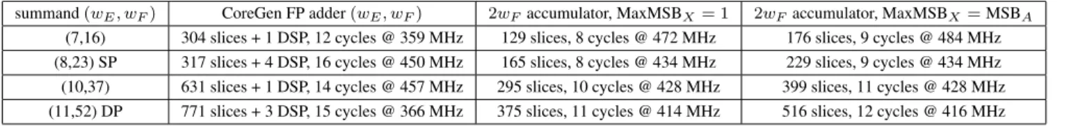
(7,16) 304 slices + 1 DSP, 12 cycles @ 359 MHz 129 slices, 8 cycles @ 472 MHz 176 slices, 9 cycles @ 484 MHz (8,23) SP 317 slices + 4 DSP, 16 cycles @ 450 MHz 165 slices, 8 cycles @ 434 MHz 229 slices, 9 cycles @ 434 MHz (10,37) 631 slices + 1 DSP, 14 cycles @ 457 MHz 295 slices, 10 cycles @ 428 MHz 399 slices, 11 cycles @ 428 MHz (11,52) DP 771 slices + 3 DSP, 15 cycles @ 366 MHz 375 slices, 11 cycles @ 414 MHz 516 slices, 12 cycles @ 416 MHz Table 1. Compared synthesis results for an accumulator based on FP adder, versus proposed accumulator with MSBA= wE,
LSBA= −wE, all targetted for 400MHz on a VirtexIV.
suggested by Hossam, Fahmy and Flynn [6] for use as an in-ternal representation in processor FPUs. For k = 1 one ob-tains a standard carry-save representation, but larger values of k are prefered as they take advantage of dedicated carry logic while reducing the register overhead. The FloPoCo implementation computes k out of the target frequency. For illustration, k = 30 allows to reach 400MHz on VirtexIV. The additional hardware cost is just the few additional reg-isters – 1/4 more in our figure, and 1/30 more for 400MHz accumulation.
Of course a drawback of the partial carry-save accumu-lator is that it holds its value in a non-standard redundant format. To convert to standard notation, there are two op-tions. One is to dedicate b(MSBA− LSBA)/kc cycles at the
end of the accumulation to add enough zeroes into the ac-cumulator to allow for carry propagation to terminate. This comes at no hardware cost. The other option, if the run-ning value of the accumulator is needed, is to perform this carry propagation in a pipelined way before the normalisa-tion – this is the dashed box on Figure 3. The important fact is again that this carry propagation is outside of the critical loop.
3.4. Post-normalisation unit, or not
Figure 3 also shows the FloPoCo LongAcc2FP compo-nent, that performs the conversion of the long accumulator result to floating-point. However, let us first remark that this component is much less useful than the accumulator itself. Indeed, some applications need the running sum at each cy-cle, but most applications need only the final sum and have no need for all these intermediate sums. Let us take a few examples.
In [3], the FPGA computes a very large integration – several hours– and only the final result is relevant. In such
Fig. 5. Accumulator with 4-bit partial carry-save. The boxes are full adders, bold dashes are 1-bit registers, and the dots show the critical path.
cases, of course, it makes no sense to dedicate hardware to the conversion of the accumulator back to floating-point. FPGA resources will be better exploited at speeding up the computation as much as possible. FloPoCo provides a small helper program to perform this conversion in software.
Another common case is that a single post-normalisation unit may be shared by several accumulators. For instance, a dot product of vectors of size N accumulates N num-bers before needing to convert the result back to floating-point. Therefore, in matrix operations, one pipelined LongAcc2FPmay be shared between N dot product op-erators [18].
For these reasons, it makes sense to provide LongAcc2FP as a separate component, as on Fig-ure 3. Note that the same holds for an accumulator based on an FP adder of latency l (that actually computes l interme-diate subsums). If only the final sum is needed, it may be computed in software at no extra hardware cost. However, if the running sum is needed at each cycle, it will take l − 1 additional FP adders (and some registers) to add together the l sub-sums. And finally, such a post-normalisation unit can be shared as in the long accumulator case for matrix operations [18, 2].
To sidestep this discussion, in the following, we choose to compare the performance only for the accumulators them-selves. We nevertheless provide for completeness some syn-thesis results for the post-normalisation unit in Table 2, but the reader should have in mind that comparable extra costs will plague an accumulator based on an FP adder.
Back to LongAcc2FP, it mostly consists in leading-zero counting and shifting, followed by conversion from 2’s complement to sign/magnitude, and rounding. If the accu-mulator holds a partial carry-save value, the carries need to be propagated – this simply requires dwA/ke pipeline levels,
each consisting of one k-bit adder and dwA/ke − 1 registers
of k bits. Again, all this may be performed at each cycle and pipelined arbitrarily. For an IEEE-754-like correctly-rounded conversion, one must in addition compute a sticky bit out of the discarded bits, but it is yet unclear if users are ready to pay this cost.
3.5. Performance results
Table 1 illustrates the performance of the proposed accumu-lator compared to one built using a floating-point adder from the Xilinx CoreGen tool.
For each summand size, we build accumulators of twice the size of the input significand (MSBA = wE,
LSBA = −wE) for two configurations: a small one where
MaxMSBX = 1, and a larger one where MaxMSBX =
MSBA = wE. As section 4 will show, a typical
accumula-tor will be between these two configurations. Again, these results are for illustration only: An accumulator should be built in an application-specific way.
Table 2 provides preliminary results for the current im-plementation of the LongAcc2FP post-normalisation unit.
4. APPLICATION-SPECIFIC TUNING OF ACCUMULATOR PARAMETERS
Let us now justify the claim, made in 3.2, that the many parameters of our accumulator are easy to determine on a per-application basis.
4.1. A tale of performance, and also accuracy
First note that a designer has to provide a value for MSBA
and MaxMSBX, but these values do not have to be accurate.
For instance, adding 10 bits of safety margin to MSBAhas
no impact on the latency and very little impact on area. Now from the application point of view, 10 bits mean 3 orders of magnitude: it is huge. A designer in charge of implementing a given computation on FPGA is expected to understand it well enough to bound the expected result with a margin of 3 orders of magnitude. An actual example is detailed below in 4.2. As another example, in Monte-Carlo simulations of fi-nancial markets, each accumulation computes an estimate of the value of a share. No share will go beyond, say, $100,000 before something happens that makes the simulation invalid anyway.
It may be more difficult to evaluate MaxMSBX. In
doubt, MaxMSBX = MSBA will do, but the
accumula-tor will be larger than needed, and application knowledge should help reduce it. For instance, implementers of Monte-Carlo simulation will exploit the fact that probabilities are
(wE, wF) LongAcc2FP, 2wF → wF
(7,16) 142 slices, 6 cycles @ 386 MHz (8,23) SP 304 slices, 7 cycles @ 366 MHz (10,37) 546 slices, 10 cycles @ 325 MHz (11,52) DP 863 slices, 12 cycles @ 306 MHz
Table 2. Synthesis results for a LongAcc2FP compatible with Table 1, rounding an accumulator of size 2wFto an FP
number of size wF.
smaller than 1. Another option is profiling: a typical in-stance of the problem may be run in software, instrumented to output the max and min of the absolute values of sum-mands. Again, the trust in such an approach comes from the possibility of adding 20 bits of margin for safety.
In some cases, the application will dictate MaxMSBX
but not MSBA. In this case, one has to consider the number
n of terms to add. Again, one will usually be able to provide an upper bound, be it the extreme case of 1 year running at 500MHz, or 253 cycles. In a worst-case scenario on such simulation times, this suggests the relationship MSBA =
MaxMSBX+ 53 to avoid overflows. For comparison, 53 is
the precision of a DP number, so the cost of this worst case scenario is simply a doubling of the accumulator itself, but not of the input shifterwhich shifts up to MaxMSBXonly. It
will cost just slightly more than 53 LUTs in the accumulator (although much more in the post-normalisation unit if one is needed).
The last parameter, LSBA, allows a designer to manage
the tradeoff between precision and performance. First, re-mark that if a summand has its LSB higher than LSBA(case
of the 5 topmost summands on Figure 4), it is added ex-actly, entailing no rounding error. Therefore, the proposed accumulator will be exact (entailing no roundoff error what-soever) if the accumulator size is large enough so that its LSB is smaller than those of all the inputs. Conversely, if a summand has an LSB smaller than LSBA(case of the
bot-tommost summand on Figure 4), adding it to the accumula-tor entails a rounding error of at most 2LSBA−1. In the worst case, when adding n numbers, this error will be multiplied by n and invalidate the log2n lower bits of the accumulator – note that this worst-case situation is antagonist to the one leading to the worst-case overflow. A designer may lower LSBA to absorb such errors, an example is given in next
section. Again, a practical maximum is an increase of 53 bits for 1 year of computation at 500MHz. However, in a global sense, it doesn’t make much sense to consider this worst case situation, because when a summand is added ex-actly, it is usually the result of some rounding, so it carries an error of the order of its LSB, which it adds to the accumu-lator (by not adding bits lower than its LSB). These errors, which are not due to the accumulator, will typically dwarf the rounding errors due to the accumulator. They can be re-duced by increasing wF, but this is of course outside of the
scope of this article.
All considered, it is expected that no accumulator will need to be designed larger than 100 bits.
Finally, the proposed accumulator has sticky output bits for overflows in the summands and in the accumulator, so the validity of the result can be checked a posteriori.
accuracy area latency SP FP adder acc 1.2 · 10−3 317 sl, 4 DSP 16 @ 450 MHz DP FP adder acc 2.8 · 10−15 771 sl, 3 DSP 15 @ 366 MHz
proposed acc 2.0 · 10−16 247 sl 10 @ 454 MHz Table 3. Compared performance and accuracy of different accumulators for SP summands from [3].
4.2. A case study
In the inductance computation of [3], physical expertise tells that the sum will be less than 105(using arbitrary units due to factoring out some physical constants), while profiling showed that the absolute value of a summand was always between 10−2and 2.
Converting to bit weight, and adding two orders of mag-nitude (or 7 bits) for safety in all directions, this defines MSBA = dlog2(102× 105)e = 24, MaxMSBX = 8 and
LSBA = −wF− 15 where wF is the significand width of
the summands. For wF = 23 (SP), we conclude that an
ac-cumulator stretching from LSBA= −23 − 15 = −38 (least
significant bit) to MSBA = 24 (most significant bit) will be
able to absorb all the additions without any rounding error: no summand will add bits lower than 2−38, and the accu-mulator is large enough to ensure it never overflows. The accumulator size is therefore wA= 24 + 38 + 1 = 63 bits.
Remark that only LSBAdepends on wF, since the other
parameters (MSBAand MaxMSBX) are related to physical
quantities, regardless of the precision used to simulate them. This illustrates that LSBA is the parameter that allows one
to manage the accuracy/area tradeoff for an accumulator. 4.3. Accuracy measurements
Table 3 compares for accuracy and performance the pro-posed accumulator to one built using Xilinx CoreGen. To evaluate the accuracies, we computed the exact sum using multiple-precision software on a small run (20,000,000 sum-mands), and the accuracy of the different accumulators was computed with respect to this exact sum. The proposed ac-cumulator is both smaller, faster and more accurate than the ones based on FP adders. This table also shows that for pro-duction runs, which are 1000 times larger, a single-precision FP accumulator will not offer sufficient accuracy.
Table 4 provides other examples of the final relative ac-curacy, with respect to the exact sum, obtained by using an FP adder, and using the proposed accumulator with twice as large a significand. In the first column, we are adding n numbers uniformly distributed in [0,1]. The sum is expected to be roughly equal to n/2, which explains that the result be-comes very inaccurate for n = 1, 000, 000: as soon as the sum gets larger than 217, any new summand in [0,1] is sim-ply shifted out and counted for zero. This problem can be anticipated by using a larger significand, or a larger MSBA
sum size rel. error for unif[0, 1] rel. error for unif[-1, 1] FP adder long acc. FP adder long acc. 1000 -5.76e-05 1.05e-07 -1.59e-05 1.40e-04 10,000 -2.74e-04 1.07e-08 -3.04e-04 2.36e-04 100,000 -4.31e-04 1.07e-09 2.54e-03 -2.73e-04 1,000,000 -0.738 -3.57e-09 3.18e-03 -4.47e-05 Table 4. Accuracy of accumulation of FP(7,16) numbers, using an FP(7,16) adder, compared to using the proposed accumulator with 32 bits (M SBA = 20, LSBA = −11).
in the accumulator as we do. In the second column, numbers are uniformly distributed in [-1,1]. The sum grows as well (it is a random walk) but much more slowly. As we have taken a fairly small accumulator (LSBA= −11), for the first sums
floating-point addition is more accurate: while the sum is smaller than 1, its LSB is smaller than −16. However, as more numbers are added, the sum grows. More and more of the bits of a summand are shifted out in the FP adder, but kept in the long accumulator, which becomes more accurate. Note that by adding only 5 bits to it (LSBA = −16 instead
of −11), the relative error becomes smaller than 10−10 in all cases depicted in Table 4: Again, LSBAis the parameter
allowing to manage the accuracy/area tradeoff.
We have discussed in this section only the error of the long fixed-point accumulator itself (the upper part of Fig. 3). If its result is to be rounded to an FP(7,16) number using the post-normalisation unit of Figure 3, there will be a relative rounding error of at most 2−17 ≈ 0.76 · 10−5.
Compar-ing this value with the relative errors given in Table 4, one concludes that the proposed accumulator, with the given pa-rameters, always leads to a result accurate to the two last bits of an FP(7,16) number.
5. ACCURATE SUM-OF-PRODUCTS
We now extend the previous accumulator to a highly rate sum-of-product operator. The idea is simply to accu-mulate the exact results of all the multiplications. To this purpose, instead of standard multipliers, we use exact mul-tipliers which return all the bits of the exact product: for 1 + wF-bit input significand, they return an FP number with
a 2 + 2wF-bit significand. Such multipliers incur no
round-ing error, and are actually cheaper to build than the stan-dard (wE, wF) ones. Indeed, the latter also have to compute
2wF+ 2 bits of the result, and in addition have to round it.
In the exact FP multiplier, results do not need to be rounded, and do not even need to be normalised, as they will be im-mediately sent to the fixed-point accumulator. There is an additional cost, however, in the accumulator, whose input shifter is twice as large.
This idea was advocated by Kulisch [8] for inclusion in microprocessors, but a generic DP version requires a 4288
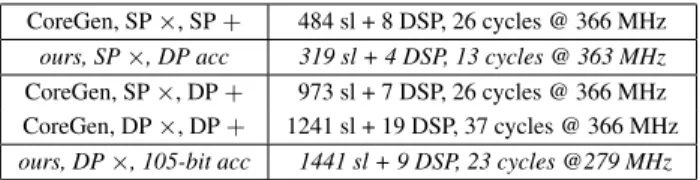
bits accumulator, which manufacturers always considered too costly to implement. On an FPGA, one may design an application-specific version with an accumulator of 100-200 bits only. This is being implemented in FloPoCo, and Ta-ble 5 provides preliminary synthesis results for single and double precision input numbers, with the same 2wF
accu-mulators as in Table 1. Some work is still needed to bring the FloPoCo multiplier generator to CoreGen level.
6. COMPARISON WITH RELATED WORK Luo and Martonosi [14] have described an architecture for the accumulation of SP numbers that uses two 64-bit fixed-point adders. It first shifts the input data according to the 5 lower bits of the exponent, then sends it to one of the fixed-point accumulators depending on the higher exponent bits. If these differ too much, either the incoming data or the cur-rent accumulator is discarded completely, just as in an FP adder. This design is much more complex than ours, and the critical path of the accumulator loop includes one 64-bit adder and a 3-2 compressor. The main problem with this ap-proach, however is that it is a fixed design that will not scale beyond single-precision. Another one is that the detection of accumulator overflow may stall the operator, leading to a variable-latency design. The authors suggest a workaround that imposes a limit on the number of summands to add.
He et al [7] have suggested group-alignment based floating-point accumulation. The idea is to first buffer the inputs into groups of size m (with m = 16 in the paper), while keeping trace of the largest exponent of a group. Then all the numbers in a group are aligned with this largest-magnitude number, and added in a fixed-point accumulator larger than the significands (30 bits for SP numbers). All this can be run at very high frequency. Then, these partial sums are fed to a final stage of FP accumulation that may run at 1/m the frequency of the first stage, and may therefore use a standard unpipelined FP adder. The authors also show that this accumulator is more accurate than one based on a stan-dard FP adder. Again, this is a very complex design (for SP, 443 slices without the last stage, 716 with it). Besides, the frequency of the group accumulator will not scale well to higher precisions without resorting to techniques similar to our partial carry save.
Zhuo and Prasanna [18], then Bodnar et all [2] have described high-throughput matrix operations using standard
CoreGen, SP ×, SP + 484 sl + 8 DSP, 26 cycles @ 366 MHz ours, SP×, DP acc 319 sl + 4 DSP, 13 cycles @ 363 MHz CoreGen, SP ×, DP + 973 sl + 7 DSP, 26 cycles @ 366 MHz CoreGen, DP ×, DP + 1241 sl + 19 DSP, 37 cycles @ 366 MHz ours, DP×, 105-bit acc 1441 sl + 9 DSP, 23 cycles @279 MHz Table 5. Preliminary results for Sum-Of-Product operators
FP adders scheduled optimally thanks to additional buffers or memories. Performance-wise, this approach should be comparable to ours. The advantage of our approach is its better genericity and its finer control of the accuracy-performance tradeoff.
7. CONCLUSION AND FUTURE WORK The accumulator design presented in this article perfectly illustrates the philosophy of the FloPoCo project: Floating-point on FPGA should make the best use of the flexibility of the FPGA target, not re-implement operators available in processors. By doing so, one comes up with a fairly simple design which can be tailored to be arbitrarily faster and ar-bitrarily more accurate than a naive floating-point approach, without requiring more resources.
This is done in an application-specific manner, and re-quires the designer to provide bounds on the orders of mag-nitudes of the values accumulated. We have shown that these bounds can be taken lazily. In return, the designer gets not only improved performance, but also a provably accurate ac-cumulation process. We believe that this return is worth the effort, especially considering the overall time needed to im-plement a full floating-point application on an FPGA.
The challenge is now to integrate such advanced oper-ators in the emerging C-to-FPGA compilers. A profiling-based approach might be enough to set up the proposed ac-cumulator. In parallel, FloPoCo should be extended with tools that help a designer set up a complete floating-point datapath, managing synchronisation issues but also accuracy ones. Such tools are still at the drawing board.
8. REFERENCES
[1] P. Belanovi´c and M. Leeser. A library of parameter-ized floating-point modules and their use. In Field Programmable Logic and Applications, volume 2438 of LNCS, pages 657–666. Springer, 2002.
[2] M. R. Bodnar, J. R. Humphrey, P. F. Curt, J. P. Dur-bano, and D. W. Prather. Floating-point accumulation circuit for matrix applications. In FCCM, pages 303– 304. IEEE Computer Society, 2006.
[3] O. Cret¸, F. de Dinechin, I. Trestian, R. Tudoran, L. Cret¸, and L. Vˇacariu. FPGA-based acceleration of the computations involved in transcranial magnetic stimulation. In Southern Programmable Logic Confer-ence, pages 43–48. IEEE, 2008.
[4] M. deLorimier and A. DeHon. Floating-point sparse matrix-vector multiply for FPGAs. In Field-Programmable Gate Arrays, pages 75–85. ACM, 2005.
[5] Y. Dou, S. Vassiliadis, G. K. Kuzmanov, and G. N. Gaydadjiev. 64-bit floating-point FPGA matrix multi-plication. In Field-Programmable Gate Arrays, pages 86–95. ACM, 2005.
[6] H. A. H. Fahmy and M. J. Flynn. The case for a redun-dant format in floating point arithmetic. In 16th Sym-posium on Computer Arithmetic, pages 95–102. IEEE Computer Society, 2003.
[7] C. He, G. Qin, M. Lu, and W. Zhao. Group-alignment based accurate floating-point summation on FPGAs. In ERSA, pages 136–142, 2006.
[8] U. W. Kulisch. Advanced Arithmetic for the Digi-tal Computer: Design of Arithmetic Units. Springer-Verlag, 2002.
[9] B. Lee and N. Burgess. Parameterisable floating-point operators on FPGAs. In 36th Asilomar Conference on Signals, Systems, and Computers, pages 1064–1068, 2002.
[10] Y. Li and W. Chu. Implementation of single precision floating point square root on FPGAs. In IEEE Sym-posium on FPGAs for Custom Computing Machines, pages 56–65, 1997.
[11] G. Lienhart, A. Kugel, and R. M¨anner. Using floating-point arithmetic on FPGAs to accelerate scientific N-body simulations. In FPGAs for Custom Computing Machines. IEEE, 2002.
[12] W. Ligon, S. McMillan, G. Monn, K. Schoonover, F. Stivers, and K. Underwood. A re-evaluation of the practicality of floating-point operations on FPGAs. In IEEE Symposium on FPGAs for Custom Computing Machines, 1998.
[13] J. Liu, M. Chang, and C.-K. Cheng. An iterative divi-sion algorithm for FPGAs. In ACM/SIGDA 14th inter-national symposium on Field programmable gate ar-rays, pages 83–89. ACM, 2006.
[14] Z. Luo and M. Martonosi. Accelerating pipelined in-teger and floating-point accumulations in configurable hardware with delayed addition techniques. IEEE Transactions on Computers, 49(3):208–218, 2000. [15] E. Roesler and B. Nelson. Novel optimizations for
hardware floating-point units in a modern FPGA ar-chitecture. In Field Programmable Logic and Applica-tions, volume 2438 of LNCS, pages 637–646. Springer, 2002.
[16] N. Shirazi, A. Walters, and P. Athanas. Quantitative analysis of floating point arithmetic on FPGA based custom computing machine. In FPGAs for Custom Computing Machines, pages 155–162. IEEE, 1995.
[17] L. Zhuo and V. Prasanna. Scalable and modular algo-rithms for floating-point matrix multiplication on FP-GAs. In Reconfigurable Architecture Workshop, Intl. Parallel and Distributed Processing Symposium. IEEE Computer Society, 2004.
[18] L. Zhuo and V. K. Prasanna. High performance linear algebra operations on reconfigurable systems. In ACM/IEEE conference on Supercomputing. IEEE, 2005.
![Table 3. Compared performance and accuracy of different accumulators for SP summands from [3].](https://thumb-eu.123doks.com/thumbv2/123doknet/14646948.736377/7.918.482.808.120.229/table-compared-performance-accuracy-different-accumulators-sp-summands.webp)