HAL Id: inria-00352092
https://hal.inria.fr/inria-00352092
Submitted on 12 Jan 2009
HAL is a multi-disciplinary open access
archive for the deposit and dissemination of
sci-entific research documents, whether they are
pub-lished or not. The documents may come from
teaching and research institutions in France or
abroad, or from public or private research centers.
L’archive ouverte pluridisciplinaire HAL, est
destinée au dépôt et à la diffusion de documents
scientifiques de niveau recherche, publiés ou non,
émanant des établissements d’enseignement et de
recherche français ou étrangers, des laboratoires
publics ou privés.
A decoupled image space approach to visual servo
control of a robotic manipulator.
R. Mahony, Tarek Hamel, François Chaumette
To cite this version:
R. Mahony, Tarek Hamel, François Chaumette. A decoupled image space approach to visual servo
control of a robotic manipulator.. IEEE Int. Conf. on Robotics and Automation, ICRA’02, 2002,
Washington DC, United States. pp.3781-3786. �inria-00352092�
A D e c o u p l e d I m a g e Space A p p r o a c h to V i s u a l Servo C o n t r o l
of a R o b o t i c M a n i p u l a t o r
Robert Mahony
Dep. of Eng.,
Australian Nat. Uni.,
ACT, 0200 Australia.
email: mahony0ieee, org
Tarek Hamel
Cemif-SC FRE-CNRS 2494,
40 rue du Pelvoux,
91020 Evry France.
email: t h a m e l 0 i u p . u n i v - e v r y , f rFrancois Chaumette
Irisa/Inria Rennes,
Campus Universitaire de Beaulieu,
35042 Rennes, France.
email: Francois. C h a u m e t t e @ i r i s a . f r
A b s t r a c t
An image-based visual servo control is presented for a robotic manipulator. The proposed control design ad- dresses visual servo of 'eye-in-hand' t y p e systems. Us- ing a novel representation of the visual error based on a spherical representation of t a r g e t centroid information along with a measure of the rotation between the c a m e r a and the target, the control of the position and orientation is decoupled. A non-linear gain introduced into the ori- entation feedback kinematics prevents the t a r g e t image from leaving the visual field. Semi-global convergence of the closed loop system is proved.
1 I n t r o d u c t i o n
Visual servo algorithms have been extensively developed in the robotics field over the last ten years [7, 19]. Most visual servo control has been developed for serial-link robotic m a n i p u l a t o r s with the c a m e r a typically m o u n t e d on the end-effector [12]. Visual servo systems m a y be divided into two main classes [15]: Position-based visual
scrvo (PBVS) involves reconstruction of the t a r g e t pose with respect to the robot and results in a Cartesian too- tion planning problem. Problems with this approach in- elude the necessity of an accurate 3D model of the target, sensitivity to c a m e r a calibration errors, poor robustness of pose estimation and the t e n d e n c y for image features to leave the c a m e r a field of view during the task. Image-
based visual scrvo (IBVS) t r e a t s the problem as one of controlling features in the image plane, such t h a t moving features to a goal configuration implicitly results in the task being accomplished [7]. Feature errors are m a p p e d to a c t u a t o r inputs via the inverse of an image Jacobian matrix. Features can be derived from image features such as points, lines and circles. Issues associated with opti- real selection of features and partitioned control where some task degrees of freedom are controlled visually and others by position or force [13, 2] have been considered in depth. IBVS avoids m a n y of the robustness and calibra- tion problems associated with PBVS, however, it has its own problems [31 . Foremost in the classical approach is
the need to determine d e p t h information for each feature point in the visual data. Various approaches have been reported including estimation via partial pose estimation [15], adaptive control [17] and estimation of the image Ja- cobian using quasi-Newton techniques [11, 18]. More re- cently, there has been considerable interest in hybrid con- trol m e t h o d s whereby translational and rotational control are t r e a t e d separately [15, 6]. Hybrid methods, however, share with the P BVS approach a difficulty to keep all image features within the camera's field of view. Con- t e m p o r a r y work [16, 4] aims to address these issues. In this p a p e r we propose an image-based visual servo control for a robotic manipulator. T h e model consid- ered is t h a t of an 'eye-in-hand' type configuration, where the c a m e r a is a t t a c h e d to the end effector of the robotic arm. The approach taken is based on recent work by the authors [9] in which an image based error is introduced for which the dynamics have certain passivity-like prop- erties. T h e visual error representation used is based on a spherical representation of target centroid information. Using this representation it is possible to express the po- sition and orientation kinematics of the visual error as a partially decoupled system. An exponentially stable feedback law is proposed for stabilization of the position. T h e feedback law for the orientation kinematics is modi- fied via a simple non-linear gain to ensure t h a t the t a r g e t image never leaves the field of vision of the camera.
2 I m a g e B a s e d E r r o r s
In this section an image based error m e a s u r e m e n t for a visual servo task is introduced.
Let Z = {Ex, Ey, Ez} denote a right-hand inertial frame. Let the vector ~ = ( x , y , z ) denote the position of the focal centre of the c a m e r a in the inertial frame. Let A - {E~, E~, E~} be a (right-hand) b o d y fixed frame for the camera. The orientation of the c a m e r a is given by the r o t a t i o n / ~ : A + Z.
Let P represent a s t a t i o n a r y point t a r g e t visible to the
Proceedings of the 2002 IEEE International Conference on Robotics & Automation
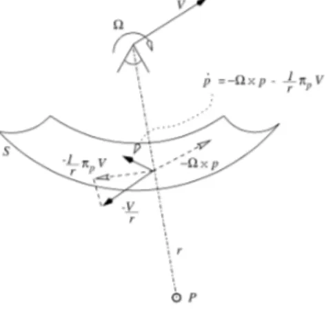
c a m e r a expressed in t h e c a m e r a frame. T h e i m a g e point observed by t h e c a m e r a is d e n o t e d p a n d is o b t a i n e d by rescaling onto t h e i m a g e surface 8 of t h e c a m e r a (cf. Fig- ure 1)
1
p
--r(p) P.
(1)
Following t h e a p p r o a c h i n t r o d u c e d in [10] we consider a c a m e r a w i t h a spherical i m a g e plane. T h u s 1 r ( P ) - P .
Let V C ,,4 d e n o t e t h e linear velocity a n d gt C ,,4 d e n o t e t h e a n g u l a r velocity of t h e c a m e r a b o t h e x p r e s s e d in t h e c a m e r a frame. T h e d y n a m i c s of an i m a g e point for a spherical c a m e r a of i m a g e surface r a d i u s u n i t y are (see E 9, 8]) 7I'p
(p)v,
(9)
w h e r e :rp - ( I 3 - p p r ) is t h e p r o j e c t i o n :rp" R 3 + T p S 2, t h e t a n g e n t space of t h e s p h e r e S 2 at t h e point p ¢ S 2. 1 ', /~ = - ~ x p - -r-Xp v ,: S r i r t O PFigure 1: Image dynamics for spherical camera image ge- ometry.
For a given t a r g e t t h e centroid is defined to be n
q " - c a 3 ( 3 ) i = 1
w h e r e t h e t a r g e t consists of n points {P~}. Using cen- t r o i d i n f o r m a t i o n is an old t e c h n i q u e in visual servo con- trol [1, 14, 211. A m o n g t h e a d v a n t a g e s of using t h e t a r g e t centroid as a visual f e a t u r e one has t h a t it is not neces- sary to m a t c h observed i m a g e points directly to desired f e a t u r e s a n d t h a t t h e calculation of a i m a g e c e n t r o i d is a highly r o b u s t p r o c e d u r e . T h e s e p r o p e r t i e s are e x p e c t e d to ensure s t r o n g p r a c t i c a l r o b u s t n e s s of t h e p r o p o s e d con- trol design. N o t e t h a t t h e centroid defined above contains m o r e i n f o r m a t i o n t h a n a classical definition. This m a y be seen from t h e fact t h a t t h e n o r m of q is r e l a t e d to t h e av- erage d e p t h of t h e t a r g e t points.
1 T h e n o t a t i o n x[ r e p r e s e n t s t h e n o r m of a n y v e c t o r x C R n
( ~ 1 - ~ ) .
Consider t h e case of a t a r g e t c o m p r i s i n g a finite n u m b e r of point t a r g e t s . Recalling Eq. 2 it m a y be verified t h a t
× q - 0v,
(4)
w h e r e
/ ~ 1 7rp~
O - .
(5)
T h e visual servo t a s k considered is t h a t of p o s i t i o n i n g a c a m e r a relative to a s t a t i o n a r y (in t h e inertial frame) tar- get. In a d d i t i o n to visual i n f o r m a t i o n a d d i t i o n a l inertial i n f o r m a t i o n is explicitly used in t h e error formulation. In p a r t i c u l a r , it is a s s u m e d t h a t t h e o r i e n t a t i o n of t h e c a m e r a w i t h r e s p e c t to t h e t a r g e t is known a priori in
t h e inertial frame. For example, one m a y wish to posi- tion t h e c a m e r a above t h e t a r g e t or to t h e n o r t h of t h e t a r g e t . N o t e t h a t t h e centroid of an i m a g e contains no i n f o r m a t i o n relative to t h e o r i e n t a t i o n t h a t can be used to position t h e c a m e r a . If p u r e l y centroid i n f o r m a t i o n is used t h e n a d d i t i o n a l i m a g e or inertial i n f o r m a t i o n m u s t be i n c o r p o r a t e d into t h e error to fully specify t h e c a m e r a o r i e n t a t i o n .
Formally, let b C Z d e n o t e t h e desired inertial direction for t h e visual error. T h e n o r m of b encodes t h e effective d e p t h i n f o r m a t i o n for t h e desired limit point. Define
b* " - R T b C ,,4
to be t h e desired t a r g e t vector expressed in t h e c a m e r a fixed frame. Since b* C ,,4 it inherits d y n a m i c s from t h e m o t i o n of t h e c a m e r a
b* - - g t x b*.
T h e i m a g e b a s e d error considered is t h e difference be- tween t h e m e a s u r e d centroid a n d t h e t a r g e t vector ex- pressed in t h e c a m e r a f r a m e
6 . - q - ( 6 )
T h e i m a g e error k i n e m a t i c s are
d -
× 6 - O v
(7)
To r e g u l a t e t h e full pose of t h e c a m e r a , it is n e c e s s a r y to consider an a d d i t i o n a l error criterion for t h e orienta- tion. N o t e t h a t any r o t a t i o n of t h e c a m e r a t h a t alters t h e observed i m a g e centroid m a y be controlled using centroid i n f o r m a t i o n . However, t h e i m a g e centroid is invariant un- der r o t a t i o n a r o u n d t h e axis of t h e centroid. Thus, t h e best t h a t can be achieved using t h e centroid f e a t u r e is to orient t h e c a m e r a such t h a t t h e i m a g e centroid lies in a desired direction. To control t h e r e m a i n i n g degrees of f r e e d o m one m u s t use a d d i t i o n a l information; either from t h e i m a g e or a prior inertial direction (linearly indepen- dent from b (see section 3.1).
In general it is desired t h a t t h e image centroid is close to t h e focal axis of the camera• This is particularly impor- t a n t if t h e r e is a risk t h a t the image m a y leave t h e active field of view of the c a m e r a during the servo manoeuvre• For the sake of simplicity we choose to stabilise the ori- e n t a t i o n in order t h a t the image centroid converges to t h e focal axis of the camera• Choose the c a m e r a frame A such t h a t t h e focal axis of t h e c a m e r a is co-linear with t h e t h i r d c o o r d i n a t e axis. Let
{el, e2, e3}
denote t h e unit vectors of t h e c o o r d i n a t e frame A. T h e visual error used for the c a m e r a orientation is the angle 0 between the cen- troid and t h e focal axisqT¢ 3
c o s 0 - -- q0Te3 a n d s i n 0 - q0 x e3 , (8)
Iql
where the normalized centroid is defined to be q0 := q/lql.
In practice, it is most convenient to work directly with the cosine of 0. Define
a " - cos 0 - q0 Te 3 .
Thus, t h e goal of the servo a l g o r i t h m is to drive 5 ~ 0 a s y m p t o t i c a l l y and stabilize a ~ 1.
3 K i n e m a t i c C o n t r o l D e s i g n
In this section a L y a p u n o v control design is given for the kinematic control of t h e visual error based on the visual errors i n t r o d u c e d in Section 2.
T h e kinematics of an image based visual servo s y s t e m are t h e first order d y n a m i c s of the visual features q and a. T h e derivative of a is
d eT3(t qeT3q
& - ~ c o s 0 - q q2
= - a ~ ( q o × ~ ) - 7~ (9)
Note t h a t angular velocity ft is t h r e e dimensional, how- ever, only the c o m p o n e n t in t h e direction q0 x e3, t h a t r o t a t e s the focal axis in the direction of t h e observed cen- troid, contributes to the first order dynamics of a. Thus, the kinematics considered are given by E q n ' s 7 and 9. T h e inputs to these equations are V a n d ft.
Define a storage function S
1 6~ (lo)
S - - ~
Taking t h e time derivative of S a n d s u b s t i t u t i n g for Eq. 7, yields
= -6TO, V
(11)
Note t h a t Eq. 11 is i n d e p e n d e n t of the angular velocity ft.
T h e m a t r i x Q > 0 is not exactly known, however, it is known to be positive definite• Thus, a choice V = 5 is sufficient to stabilise S1. T h e kinematic control chosen for Eq. 11 is
V = k65 (12)
L e m m a 3.1 Consider the system defined by Eq. 7 and
let k6 > 0 be a positive constant. A s s u m e that the image remains in the camera field of view for all time. Then, the closed loop system Eq. 7 along with control Eq. 12 exponentially stabilises the visual error 5.
P r o o f : Recalling the derivative of S a n d s u b s t i t u t i n g the control input V by its expression, it yields
= --k66TQ6
Since Q is a positive definite matrix, classical L y p u n o v t h e o r y g u a r a n t e e s t h a t 5 converges exponentially to zero.
To control the kinematics of t h e visual feature a t h e stor- age function considered is
(~ - ~o~O) ~ - ~ (~ -
~)~
T ' - 2
E
"
(13)
Following a classical L y a p u n o v control design t h e n a t u r a l choice of ft is = - k ~ (qo × e3). (14) Thus,
~ ~~oO, V)
(~5)
- (1 - ~ ) a~(qo × ~ ) +
- - k ~ ( 1 + ~ ) ( 1 - ~) ~ + qL e m m a 3.2 Consider the rotational dynamics defined
by Eq. 9 with the control law Eq. 1~. Let V be an ezpo- nentially stable signal
IvI ~ B e -~t
for positive constants B, ~ > O. A s s u m e that ]q[ > c > 0 is bounded away f r o m zero and that
]]QI]
< A < oc is bounded. Then a ~ 1 exponentially. A s a consequence 0 ~ 0 exponentially.An u n f o r t u n a t e possibility with t h e above control design is t h a t t h e t a r g e t image m a y leave field of view of t h e c a m e r a during the evolution of t h e closed loop system• To avoid such a situation it is necessary to modify the ori- e n t a t i o n control design• In particular, if the closed loop system evolves such t h a t the image is t e n d i n g to leave t h e field of view, high gain d y n a m i c s are i n t r o d u c e d in the ori- e n t a t i o n kinematics to keep t h e t a r g e t in t h e image plane•
For a given initial condition it is possible to choose a gain ks > 0 sufficiently large such t h a t the exponential sta- bility of t h e o r i e n t a t i o n dynamics d o m i n a t e s t h e c a m e r a a t t i t u d e kinematics and the c a m e r a points towards the t a r g e t centroid regardless of the linear dynamics of the camera. This a p p r o a c h is undesirable as it leads to high gain input over the full d y n a m i c s of the s y s t e m a n d re- duces system r o b u s t n e s s as a consequence. In this p a p e r a non-linear gain (linked to a barrier function potential) is used to limit t h e divergence of t h e image centroid from t h e focal axis of t h e camera.
Let the m a x i m u m allowable value for 0 be d e n o t e d 0 n > 0. T h e constraint 0 < 0,~ limits the possible orientation of the c a m e r a to a positive cone a r o u n d t h e centroid. Set a,~ = cos(0,~). T h e a p p r o a c h t a k e n is to choose the control to be
ko~
• - - ( q o ×
T h e barrier t e r m 1 / ( a - a ~ ) e n s u r e s t h a t the control
input for the orientation dynamics d o m i n a t e s any finite p e r t u r b a t i o n due to the linear velocity V if the orienta- tion approaches the limit. Recalling the definition of the storage function T, one has
- _ ( 1 - + q
L e m m a 3 . 3 Consider the rotational dynamics defined by Eq. 9. Let the control law Eq. 17. Let V be an exponentially stable signal
IvI _<
for positive constants B, ~ > O. Let 0,~ > 0(0) (a(O) > a,~). A s s u m e that
Iql
> ~ > 0 is bounded away f r o m zero and that llQIl< A < oc is bounded. Then a > a,~ f o r all time and a ---+ 1 exponentially.P r o o f : First it is necessary to show t h a t T remains b o u n d e d . Indeed, from Eq. 13 it follows t h a t T < 2. I n t r o d u c i n g b o u n d s on q a n d Q, the derivative of T m a y be b o u n d e d by the following expression
k ~ ( l + a) 4 A B e ~t
T < -
- - -Taking t h e limit of t h e above b o u n d on T when a ~ a,~, it yields
T < 0 This proves t h a t a > a,~ for all time.
T h e exponentially decreasing p e r t u r b a t i o n does not de- stroy t h e classical L y a p u n o v convergence result t h a t forces 5 b ~ 0 exponentially a n d g u a r a n t e e s t h a t a ~ 1
exponentially. •
3 . 1 S t a b i l i s a t i o n o f r e m a i n i n g o r i e n t a t i o n w i t h r e f e r e n c e t o v i s u a l d a t a .
In this subsection an auxiliary control is p r o p o s e d t h a t will regulate the r e m a i n i n g degree of freedom in the atti- t u d e of t h e c a m e r a using an additional error criteria. To control t h e r e m a i n i n g o r i e n t a t i o n of a c a m e r a via an error in image space it is necessary to consider error crite- ria t h a t d e p e n d s on a n o t h e r vector direction fixed in t h e c a m e r a frame. A key observation for t h e p r o p o s e d control design is t h a t such an error is chosen and minimized af- ter the regulation of the visual errors 5 a n d 0 respectively. Thus, t h e best t h a t can be achieved is to orient the cam- era within the set 5, 0 = 0 and the auxiliary error must be chosen with this in mind. T h e control objective consid- ered is to align el as closely as possible with new visual 'feature' vector c o m p u t e d from image m e a s u r e m e n t s
i=n
- Z ( i s )
i=1
where a~ are a set of real constants. It is not required t h a t a~ > 0 and differences between observed points m a y be used to g e n e r a t e t h e visual feature q~ vector.
Define cr to be t h e error between t h e visual feature di-
qa
rection q~ (q~ -- iqal) and the c a m e r a frame direction C1.
cr - q~ - el (19)
Taking t h e derivative of or, yields
1
~ - - - - Q X cr + - - 7 c a Q a V - e2 Q3 + e3 Q2 (20)
qa qo
Let U be the storage function for the error criterion or.
1 2
U - 2 c r
Deriving U and recalling t h e derivative expression of or, yields
_ _o_T ( 1
-~ff£-iTCq~QaV - e3Q 2 + e2 Q3
k
qChoose t h e control for gt 3 to be
~'-~3 __ kcre T O- ( 2 1 )
T h e derivative of U becomes now,
0 -- -o-T~,-yV @ O-Te3 ~2 -- ]~crGTe2eTG 1
(22)
L e m m a 3.4 Consider the remaining rotational dynam- ics defined by Eq. 19 with the control law Eq. 21. Let V and f~2 be exponentially stable signals
Q2 V < B e - m
for positive constants B, ~ > O. A s s u m e that qa > c > 0 is bounded away f r o m zero and that Qa < A < cx~ is bounded. Then ~ ~ 0 exponentially.
Sketch of P r o o f Similar to the case encountered in L e m m a 3.2 the Lyapunov function U need not be mono- tonically decreasing and stabilizing part of the right-hand of Eq. 22 is not negative definite. Nevertheless, using the fact t h a t b o t h V and gt 2 are exponentially stable (cf. L e m m a s 3.1 and 3.2) then a result proving convergence of eTcr to zero is possible. L e m m a ' s 3.2 and 3.4 provide a complete characterisation of the convergence of the ori- entation of the camera. This can be seen by confirm- ing t h a t L e m m a 3.2 guarantees t h a t the e3 axis of the c a m e r a frame is aligned in the direction of the centroid q. T h e c a m e r a m a y still be r o t a t e d around the e3 axis without changing the convergence result obtained, how- ever, L e m m a 3.4 ensures convergence of q~ into the plane given by span{el, e3}. Since e3 is g u a r a n t e e d to lie in the direction of the centroid q t h e n e l must lie in the unique direction
e l C I F~ ~ •
/k
4 E x p e r i m e n t a l results
In this section experimental results are presented. Our aim is to validate the proposed image-based approach, showing, in real conditions, the convergence and robust- ness.
T h e control law has been tested on a six d.o.f. Cartisian robot A F M A (at Irisa/Inria-Rennes). T h e c a m e r a was m o u n t e d on the end-effector of the robot. In this ex- periment a basic stabilization task is considered. T h e target is the four black m a r k s on the vertices of a pla- nar square. Each vertex is of 0.04m of length. T h e signals available are the normalized co-ordinates of the center of the four marks observed by the camera, de- noted { ( / Z l , / ) 1 ) , ( / Z 2 , / ) 2 ) , ( / Z 3 , / ) 3 ) , ( / Z 4 , / ) 4 ) } . These coordi- nates are transformed, in the computer, into normalized spherical coordinates (x~, y~, z~).
T h e desired t a r g e t vector b* is chosen such t h a t the cam- era set point is located at 0.2m above the square. Figure 2 shows the initial and goal image a p p e a r a n c e of the tar- get. T h e end-effector of the robot is moved according to the control laws Eqn's 12, 17 and 21.
In this experiment, the barrier t e r m is obtained from the initial condition; it is chosen to be ( c ~ = 0.g cos0(0)). T h e following control gains are used, ks = k~ = 0.07. T h e control gain /ca is chosen to be a constant m a t r i x /c6 = 0.07Q *-1. This choice is used to avoid the con- ditioning problem of the m a t r i x Q and to decouple the dynamics of the components of 5. We have proved t h a t Q Q , - 1 is positive definite matrix, however, due to space limitations the proof is o m i t t e d and m a y be obtained on application to the authors. T h e constants a~ used
i!
iii~::.!.
F i g u r e 2: Initial image and desired appearance of the target.
in the definition of the variable cr have been fixed to [1, 1, - 1, - 1]. T h e algorithm performance is satisfactory : the pixel trajectories of the image points (cf. Figures 4 and 3) show a good convergence of the difference between the e x t r a c t e d and desired features. The convergence and stability of the positioning process is shown in Figure 5.
/ . . . f / / / i . - / i / ... i i i i i i i 0 'tO.dat' ,~i dc, t 't2.dat' 't3 d~t'
F i g u r e 3: Image point trajectories
'er::;," :ia*: .sing i 0.15 'error.dat' using 3 .:,,.,:,: ,:,,:.::: ,,:.::;: 01 i ". . ... . .... g • 'error.c:at' using . . . i( f -o.2 -0.25 -O.S , , , , , , , , 0
F i g u r e 4: Error on the coordinates of the image features.
5 C o n c l u d i n g r e m a r k s
In this p a p e r a novel representation of the visual error, based on a spherical representation of t a r g e t centroid in- formation, along with a Lyapunov control design is used to decouple the position and orientation servo control de- sign for an image based visual servo system. In contrast to other recent work [5] the proposed servo control de- sign does not need separate d e p t h of target estimates. Moreover, the framework used leads to a simple barrier
0.6 0.4 ,-, 0.2 o - -o.2 -o.4 -o.6 -o.8 -1 -1.2 -1.4 o , / 'del[a.da'_ r' t~sir~g 1 'clelta dat' using 3
F i g u r e 5: Exponential evolution of the error 5.
function technique that is proposed to guard against the observed target leaving the field of view of the camera without otherwise effecting the performance of the algo- rithm.
6 A c k n o w l e d g m e n t s
The authors wish to thank Peter Corke for numerous helpful discussions.
R e f e r e n c e s
[11 R . L . Andersson. A Robot Ping-Pong Player: Ex-
periment in Real-Time Intelligent Control. MIT Press,
Cambridge, MA, USA, 1988.
[21 A. Castano and S. Hutchinson. Visual compliance: Task directed visual servo control. IEEE trasnactions on
Robotics and Automation, 10(3):334-341, June 1993.
[31 F. Chaumette. Potential problems of stability and convergence in image-based and position-based visual ser- voing. In The Confluence of Vision and Control, LNCIS, No. 237 pp. 66-78, 1998.
[41 P . I . Corke and S. A. Hutchinson. A new parti- tioned approach to image-based visual servo control. In
Proceedings of the International Symposium on Robotics,
Montreal, Canada, May 2000.
[51 P . I . Corke and S. A. Hutchinson. A new hybrid image-based visual servo control scheme. IEEE Int. Conf. on Decision and Control, CDC'2000, Sydnet, Australia, December 2000.
[61 K. Deguchi. Optimal motion control for image- based visual servoing by decoupling translation and rota- tion. In Proceedings of the International Conference on
Intelligent Robots and Systems, pages 705-711, 1998.
[71 B. Espiau, F. Chaumette, and P. Rives. A new ap- proach to visual servoing in robotics. IEEE Transactions
on Robotics and Automation, 8(3):313-326, 1992.
[81 C. Fermuller, Y. Aloimonos. Observability of 3D motion. Int. Journal of Computer Vision, 37(1):43-64, June 2000.
[9] T. Hamel and R. Mahony. Robust visual servo- ing for under-actuated dynamic systems. In Proceedings
of the Conference on Decision and Control, CDC'2000,
Sydney, N.S.W., Australia, 2000.
[10] T. Hamel and R. Mahony. Visual servoing of an under-actuated dynamic rigid-body system: An image based approach. Provisionally accpeted for publication in IEEE Transactions on Automation and Robotics, Sub- mitted June 2000, 2001.
[11] K. Hosada and M. Asada. Versatile visual servo- ing without knowledge of true jacobian. In Proceedings
of the I E E E / R S J International Conference on Intelligent Robots and Systems, pages 186-193, Munich, Germany,
1994.
[12] S. Hutchinson, G. Hager, and P. Cork. A tutorial on visual servo control. IEEE Transactions on Robotics
and Automation, 12(5):651-670, 1996.
[13] K. P. Khosla, N. Papanikolopoulos, and B. Nel- son. Dynamic sensor placement using controlled active vi- sion. In Proceedings of IFA C 12th World Congress, pages 9.419-422, Sydney, Australia, 1993.
[14] M. Lei and B. K. Ghosh. Visually guided robotic motion tracking. In Proceedings of the thirteenth Annual
Conference on Communication, Control and Computing,
pages 712-721, 1992.
[15] E. Malls, F. Chaumette, and S. Boudet. 2-1/2- d visual servoing. IEEE Transactions on Robotics and
Automation, 15(2):238-250, April 1999.
[16] G. Morel, T. Liebezeit, J. Szewczyk, S. Boudet, and J. Pot. Explicit incoporation of 2D constraints in vision
based control of robot manipulators, volume 250 of Lecture Notes in Control and Information Sciences, pages 99-
108. Springer-Verlag, New York, USA, 1999. Edited by P. Corke and J. Trevelyan.
[17] N. Papanikolopoulos, P. K. Khosla, and T. Kanade. Adaptive robot visual tracking. In Proceedings of the
American Control Conference, pages 962-967, 1991.
[18] J . A . Piepmeier. A dynamic quasi-newton method
for model independent visual servoing. P hd, Georgia In-
stitute of Technology, Atlanta, USA, July 1999.
[19] R. Pissard-Gibollet and P. Rives. Applying visual servoing techniques to control of a mobile hand-eye sys- tern. In Proceedings of the IEEE International Conference
on Robotics and Automation, ICRA'95, pages 166-171,
Nagasaki, JAPAN, 1995.
[20] C. Samson, M. Le Borgne, and B. Espiau. Robot
Control: The task function approach. The Oxford Engi-
neering Science Series. Oxford University Press, Oxford, U.K., 1991.
[21] B. Yoshimi and P. K. Allen. Active, uncalibrated visual servoing. In Proceedings of the IEEE International
Conference on Robotics and Automation, ICRA '9~, pages
156-161, San Diago, CA, USA, 1994.