HAL Id: hal-01934989
https://hal.archives-ouvertes.fr/hal-01934989
Submitted on 26 Nov 2018HAL is a multi-disciplinary open access
archive for the deposit and dissemination of sci-entific research documents, whether they are pub-lished or not. The documents may come from teaching and research institutions in France or abroad, or from public or private research centers.
L’archive ouverte pluridisciplinaire HAL, est destinée au dépôt et à la diffusion de documents scientifiques de niveau recherche, publiés ou non, émanant des établissements d’enseignement et de recherche français ou étrangers, des laboratoires publics ou privés.
Designing magnetic composite materials from aqueous
magnetic fluids
José Galicia, Olivier Sandre, Fabrice Cousin, Dihya Guemghar, Christine
Ménager, Valérie Cabuil
To cite this version:
José Galicia, Olivier Sandre, Fabrice Cousin, Dihya Guemghar, Christine Ménager, et al.. Designing magnetic composite materials from aqueous magnetic fluids. Journal of Physics: Condensed Matter, IOP Publishing, 2003, 15 (15), pp.S1379-S1402. �hal-01934989�
Designing magnetic composite materials from aqueous magnetic fluids
José Alberto GALICIA*, Olivier SANDRE*, Fabrice COUSIN†, Dihya GUEMGHAR*, Christine MENAGER* and Valérie CABUIL*
*Laboratoire Liquides Ioniques et Interfaces Chargées – Equipe Colloïdes Inorganiques UMR 7612 CNRS / Université Pierre et Marie Curie (Paris 6)
4 place Jussieu, case 63 – 75252 Paris cedex 05, France Fax: (33) 1 44 27 36 75
†Laboratoire Léon Brillouin, UMR 12 CNRS / CEA CEA-Saclay – 91191 Gif-sur-Yvette, France
Abstract:
In this paper, we report how to take advantage of the good knowledge of both the chemistry and the stability of an aqueous magnetic colloidal suspension to realize different magnetic composites. The osmotic pressure of the magnetic nanoparticles is set prior to the realization of the composite to a given value specially designed for the purpose of each hybrid material: magnetic particles in polymer networks, particles as probes for studying the structure of clay suspensions and shape modification of giant liposomes.
At first, we show that the introduction of magnetic particles in polyacrylamide gels enhances their Young modulus and reduces their swelling by water. The particles cause both a mechanical and an osmotic effect. The latter is strongly dependant on the ionic strength and attributed to an attraction between particles and polymeric matrix.
In the second part, we determine the microscopic structure of suspensions of laponite as a function of concentration, by combining SANS and magneto-optical experiments with the probes. This study requests conditions for including the magnetic particles as probes without disturbing the clay suspensions.
The third part presents giant magnetoliposomes, which encapsulate magnetic nanoparticles. Shape transitions are obtained with eithera magnetic field or an osmotic stress.
Overview
Smart materials, which mean materials that respond to an external stimulus, can be obtained by associating magnetic nanoparticles to a polymeric or a lyotropic matrix. The resulting composite materials exhibit a response when they are submitted to a magnetic field of low intensity (typically less than 0.1 Tesla) or to a magnetic field gradient. Different procedures can be imagined to produce such materials: the magnetic particles can be either synthesized directly inside a host matrix, or synthesized first, then mixed with the other component of the composite. These last years, magnetic nanoparticles have been successfully introduced in glass [1], polymeric gels [2, 3], lyotropic systems (nematics [4], smectics [5]), microscopic colloids (emulsions [6], latexes [7], liposomes [8]). They can be used as probes, in order to characterize dynamics (and subsequently structure) of the medium through the analysis of their magneto-optical response [9], or they can be introduced as a magnetic load in order to obtain field dependant materials [5, 10, 11].
Aiming to improve the homogeneity of the resulting composite material, the colloidal stability of both components of the composite is of uppermost importance. The colloidal dispersion of magnetic particles has thus to be stable in the chemical and physicochemical stability domains of the second system. An eventual chemical incompatibility between the nanometric magnetic particles and the host colloid has to be examined first. A modification of the pH, an increase of the ionic strength, adsorption or desorption of the charge determining species or of the surfactants, can occur during the mixing process or few weeks after, the latter case being especially harmful, because it can be unnoticed and leads to important interpretation errors. Chemistry of magnetic colloids is now sufficiently well developed to succeed in preventing such problems. As soon as the chemical stability of both colloidal systems is controlled, interactions in the binary system have to be monitored. As a matter of fact, each colloidal system is characterized by its own osmotic pressure Π. Thus it can be roughly said that the system that has the higher osmotic pressure will impose its own pressure to the other one that can then be destabilized [12]. The osmotic pressures of the two components should thus be of the same order of magnitude for the realization of the binary system.
The aim of this paper is to illustrate this comment by describing how it has been possible during recent years to design various magnetic composite systems with always the same well-defined magnetic material: an aqueous dispersion of citrate-coated maghemite nanoparticles, that will be denoted hereafter CitMF [13]. Three examples are presented resulting from the association of CitMF with several hosts, the latter being i/ a polymeric network, ii/ a gel of inorganic particles and iii/ a lyotropic system. In the first case, the polymer is a polyacrylamide cross-linked network. The point was to trap the nanoparticles inside the mesh of the network and to compare the composite material with the undoped polymer. In the second case, the nanoparticles have been introduced in aqueous dispersions of a clay (laponite) in order to test the structure of those inorganic gels and test the hypothesis of microscopic liquid pockets coexisting with solid domains [14]. In the third case, CitMF has been encapsulated inside liposomes, thus enabling to elongate them under a magnetic field or generate their
migration under a field gradient. Among the three composite systems, laponite clay suspensions and magnetoliposomes have already been described extensively in former publications, whereas the results about the thermodynamics of ferrogels (swelling and elasticity) are unpublished before and therefore presented in more details in this article.
I. Properties of aqueous dispersions of citrate-coated particles (CitMF)
A. Getting CitMF
The maghemite nanoparticles are chemically synthesized in water by coprecipitation of FeCl2 and FeCl3 in an alkaline solution [15]. Due to the strong absorption of short wavelength light by iron oxide, maghemite ferrofluids exhibit a characteristic orange color. The colloidal particles have a quasi-spherical shape and their diameter after synthesis range between 3 and 15 nm with a rather large polydispersity. Their size distribution is described by a log-normal law with a modal diameter d0 around 7 nm ( ln d0 = < ln d > ) and a standard deviation σ = 0.35. When necessary, polydipersity can be reduced by a size-sorting process to get suspensions with d0 varying from 6 nm to 10 nm and σ = 0.1 [16]. In order to get stable suspensions from pH 4 to pH 10, particles are coated by citrate species. The adsorption equilibrium of citrate leads to an inevitable residual ionic strength
=
∑
i i i
z
c
I
22
1
hence I = 6[Cit3-]free due to the unadsorbed citrate species (Cit3-) in equilibrium with the adsorbed ones and their Na+ counterions. This equilibrium avoids decreasing the ionic strength under a given concentration that depends on the pH. At pH 7, the adsorption plateau is reached for a concentration of [Na3Cit] in solution equal to 2 10-3 mol.L-1 [17]. The particle’s surface charge is negative, saturated at a value of 2 charges.nm-2. Above pH 10 citrate desorbs, while below pH 4 the surface charge density of these citrate-coated particles becomes insufficient to ensure electrostatic repulsion.
B. Phase behavior of CitMF
The stability of CitMF has been the object of numerous studies these last years [13, 18-21]. They exhibit indeed a very rich behavior due to two specific features: the presence of adsorbed citrate ligands and the magnetic dipolar interactions.
In such systems, the main interaction between particles is the electrostatic repulsion, which stabilizes the system in a wide range of salinity. In addition, the presence of citrate at the surface of the particles provides a steric repulsion at short range that ensures stability for high salinity [13] and prevents irreversible aggregation, which usually occurs in electrostatically stabilized colloidal systems. These two repulsive interactions ensure that all transitions are reversible whatever the experimental
conditions. Magnetic dipolar interactions ensure that attractive interactions occur in the system on a larger range than Van der Waals ones and allow tuning the balance between repulsive and attractive interactions for long-range potentials.
Two regimes of interactions have been clearly identified:
i) At low ionic strength ([Cit]free < 10–2 mol.L-1), electrostatic repulsion dominates inter-particle’s interactions and the phase behavior is well described by the usual Fluid-Solid phase diagram of a repulsive system. The phase diagram of CitMF in the Π – Φ plane has been established and various iso-salinity lines have been plotted [13] allowing to set the osmotic pressure of CitMF for a given ionic strength within the fluid domain. This regime of interactions is clearly the most useful for the synthesis of composite materials as it ensures the CitMF stability. In this repulsive regime, a sample of CitMF remains a stable monophasic liquid for all intensities of magnetic field and magnetic field gradient.
ii) For a higher ionic strength ([Cit]free > 10–1 mol.L-1), the inter-particle’s potential is an attractive Lennard-Jones like one and the phase behavior of the magnetic fluid is well described by a phase diagram like for an atomic system, including gas-liquid transitions [19], the existence of a critical point [20] and fluid-solid transitions [21]. Especially gas-liquid like transitions have to be kept in mind when making composite materials, as they may appear if the ionic strength strongly increases locally in the material, even if the average ionic strength is low.
Between these two regimes, one goes smoothly from the repulsive to the attractive regime by increasing salinity. The knowledge of the phase diagrams in the different salinity regimes allows choosing the best set of conditions (Π, Φ and I) for the precursor CitMF prior to the realization of a composite material.
II. Ferrofluids and polymer networks
When dealing with composites of polymers and ferrofluids, one commonly thinks about magnetic latexes used for biotechnological applications like cell sorting. Most commercial products are based on polystyrene beads filled with magnetic particles dispersed thanks to a hydrophobic coating [7, 22]. About ten years ago, Zrínyi introduced the opposite approach of water-based polymers mixed with aqueous ferrofluids [2]. The composite material obtained by associating a hydrogel and a ferrofluid has been called a ferrogel. The purpose was to obtain soft magnetic gels easily deformed by a magnetic field gradient (magnetostriction). The matrix was for example poly(vinyl-alcohol) cross-linked by glutaraldehyde and the magnetic materials consisted in magnetite grains (Fe3O4) about 10 nm in size dispersed in an acidic medium (HClO ). Due to their high water content (more than 90%
weight!), ferrogels are much more deformable than magnetic latexes. Indeed, our own estimation of the Young modulus is about 104 Pa, which is 2 orders of magnitude lower than for classical rubbers. The goal of our study is to determine the influence of a charged ferrofluid properly dispersed in a polymer network on both the osmotic swelling equilibrium and on the mechanical elasticity of the gel. We chose to mix a citrate-stabilized ferrofluid (CitMF) with acrylamide monomer (AM) that is polymerized and cross-linked in the pre-formed colloidal suspension. Acrylamide is polymerized thermally in the presence of a low amount of free radical initiator such as persulfate (peroxodisulfate) ions. Despite its simplicity, acrylamide is very useful to build a neutral hydrophilic network.
This section is organized as follows. In the first part, we describe the synthesis of ferrogels. The second and the third parts present mechanical and osmotic measurements respectively, with ferrogels of varying composition. Finally, we discuss possible interactions between ferrofluids and polymer networks that can explain the experimental data.
A. Synthesis
The cross-linker used was N,N’-methylene-bis-acrylamide (BA) and the initiator ammonium persulfate (APS). Because APS is a 2:1 electrolyte that contributes to the ionic strength, the minimum possible concentration avoiding destabilization of the ferrofluid was used. The reactive mixture (2–3 mL) contained monomer (0.5 mol.L-1 AM), cross-linker (5·10-4 or 2.5·10-4 mol.L-1 for 1% or 0.5% BA/AM respectively), initiator (5·10-4 mol.L-1 APS), tri-sodium citrate electrolyte (Na3Cit) and ferrofluid (CitMF) at a volume fraction of magnetic nanoparticles denoted Φ0. The [Na
3Cit] concentration was either 5·10-3 or 8·10-3 mol.L-1 for the two series of experiments which will be presented later in the text. The solution was degassed for 5 min before polymerization to eliminate oxygen. Then temperature was raised up to 70°C for 2 hours to achieve completion of the reaction. Although the mixture already gelled after 15 min, this long reaction time was used to assure about 96– 98% of reacted monomer (measured yield). After careful removal, the ferrogels kept the cylindrical shape of the glass vessel (sample tube or Pasteur pipette for the swelling and the elasticity experiments respectively). After washing with deionized water to eliminate unreacted species, the ferrogels were immersed into a large volume of solution which was either pure water or a solution of Na3Cit with a concentration ranging from 5·10-4 mol.L-1 to 4·10-1 mol.L-1.
B. Elasticity measurements
Traditionally with hydrogels, the stress-strain measurements are performed in compression experiments of gel disks by using a tensile testing machine [23]. We preferred to use a home-build setup to apply a controlled elongation stress on ferrogels at equilibrium swelling, thereby visualizing
directly their stretching. Moreover, our experiment has the advantage to keep the sample in direct contact with the solvent. Of course the Young modulus measured at low strain should be the same for elongation and compression experiments.
Long cylindrical samples of ferrogel were obtained by polymerizing the AM/CitMF mixtures in Pasteur pipettes of d0= 5 mm inner diameter and 50 mm length. The ferrogels were synthesized at different volume fractions Φ0 of magnetic particles (from 1 to 7%) at a given ionic strength [Na
3Cit]0 = 8·10-3 mol.L-1 as described in the part A. Synthesis. The two extremities of the ferrogel cylinders were reinforced by polymerizing them at a higher cross-linker ratio (BA/AM=5%) than the body of the ferrogel (BA/AM=1%). In practice, the ferrogel was built in three steps corresponding to each section, added successively to the previous one still freshly polymerized (at 10 min interval). After polymerization, the ferrogels were carefully removed from the Pasteur pipettes. Special attention was paid to avoid making any crack in the body of the ferrogels, which could decrease their mechanical strength. Then they were allowed to swell in a solution at [Na3Cit] = 8·10-3 mol.L-1. Once the swelling equilibrium was reached, the ferrogels were attached by their reinforced ends to two plastic nuts, the lower one static, the upper one mobile and connected to the arm of a counterweight balance. The system was immersed in a transparent reservoir containing an aqueous solution of citrate salt at [Na3Cit] = 8·10-3 mol.L-1, thus enabling a direct observation of the colored ferrogel under extension with a video camera mounted with a 75 mm zoom lens.
The stress was applied by loading the pan of the balance with calibrated weights (M=10 g maximum). We checked that both ends of the sample were held firmly and without sliding by the nuts during the whole elongation test. The axial dimension L of the ferrogel was recorded from the initial state under zero-load L0 up to a maximum elongation state always below rupture. Usually a change of the load is followed by mechanical oscillations. Therefore a delay of 1 min between two consecutive measurements was always respected to achieve static equilibrium of the sample.
The strain is defined as:
0 0 L L L− =
ε
where L0 is the length of the gel between the two anchoring points in the unloaded state (see Fig. 1a) and L is the length when a weight M is placed on the pan of the balance. The cross-section area of the cylinder is noted A0 under zero-load and A under load. Assuming a constant volume of the sample under deformation, we have
A
=
A
0(
1
+
ε
)
. We deduce the true stress acting on the gel loaded with a weight M:(
ε
)
σ
=
1
+
0A
Mg
where g=9.8 m.s-2 is the gravity constant. Depending on the swelling degree, the diameter d of each cylindrical sample after swelling and before stretching ranges between 6.5 and 8.5 mm. The plots on
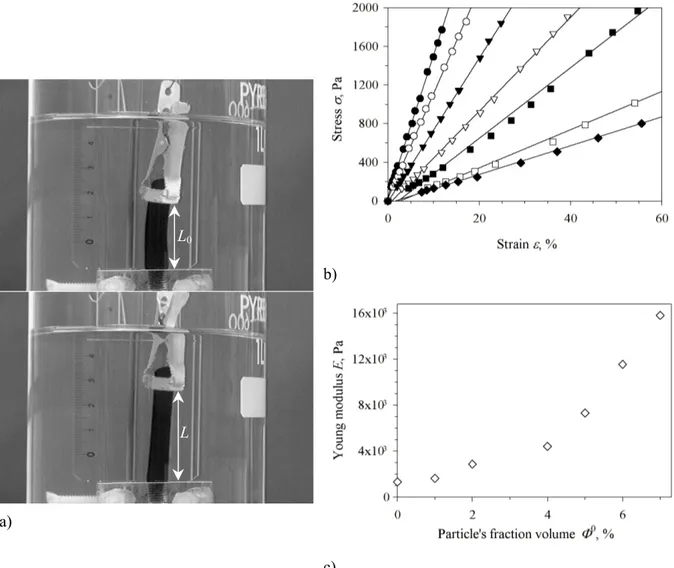
Fig. 1b represent the strain-stress measurements for ferrogels at the same polymer and cross-linker concentrations but varying volume fractions of nanoparticles Φ0 during synthesis. We observe no significant deviation of the curves from linearity, meaning that the ferrogels exhibit a rubber-like elasticity over the whole domain of deformation studied here.
a)
b)
c)
Fig. 1: a) Stretching experiment of a ferrogel in the swollen state (Φ0=4%) under controlled load (M=0 g for upper picture, M= 5.4 g for lower picture); b) Strain-stress curves obtained at constant cross-link density BA/AM=1% and [AM]=0.5 mol.L-1 during synthesis for increasing particle’s volume fraction
Φ0=0% (filled diamonds), 1% (empty squares), 2% (filled squares), 4% (empty triangles), 5% (filled triangles), 6% (empty circles) and 7% (filled circles). All these ferrogels were prepared and swollen in solutions where [Na3Cit] = [Na3Cit]0 = 8·10-3 mol.L-1; c) Elastic modulus E of the ferrogels measured from the slopes of the strain-stress curves plotted as a function of the particle’s volume fraction Φ0 during synthesis.
The Young modulus E is simply given by the slope of σ versus ε and can be plotted as a function of Φ0 (Fig. 1c). These data show that the mechanical strength of ferrogels increases significantly with the
L0
volume fraction of inorganic nanoparticles introduced at preparation. Therefore ferrogels can be considered as composite materials where the polymer matrix is reinforced by the solid component. However the elastic modulus remains around 104 Pa, which is still two orders of magnitude lower than usual values for elastomers (E~106 Pa).
C. Swelling and release
The ferrogels were allowed to reach their swelling equilibrium in Na3Cit for approximately three weeks. The immersion bath was changed several times in order to get rid of free particles that were not trapped within the ferrogel. The swollen ferrogel at equilibrium was weighted (mswollen) then dried at 70°C to obtain also its dry weight (mdry). Finally, the iron content remaining in the dried ferrogel was measured by atomic absorption spectroscopy with a hollow cathode lamp in a Pelkin Elmer AAnalyst 100 apparatus. Thus we can calculate the mass of iron oxide (mFe2O3) remaining after release of some of the magnetic particles and compare it to the mass of maghemite initially introduced in the ferrogel during the synthesis ( 0
Fe2O3
m
). Two ratios are defined from those experimental measurements:r
m
m
m
m
m
Q
polyme dry swollen polymer H2O=
−
=
and 0 Fe2O3 Fe2O3 0 Fe2O3m
m
m
R
=
−
Q is the swelling degree commonly used for hydrogels defined as the amount of water mH2O absorbed by the gel quoted by the weight of polymer network mpolymer. The water content mH2O is given by the difference of weights between the swollen gel and the dry gel. Please note that in the case of ferrogels, the dry weight consists of polymer, particles and citrate salt all together. The mass of polymer only
mpolymer has thus to be computed from the initial concentration of monomer assuming a yield of 100%. The amount of water being known precisely in the synthesis vessel, an initial value of the swelling ratio is calculated. This Q0 value ranges from 25 to 27 depending on the volume fraction Φ0 of solid iron oxide. R is the release parameter specific for ferrogels that we define as the fraction of magnetic particles which are not trapped by the ferrogel and are released in the swelling bath.
We performed two series of swelling experiments with ferrogel samples:
- We varied the volume fraction Φ0 of magnetic particles at preparation from 1 to 9% while we kept the ionic strength at a low value identical in the swelling bath and during synthesis [Na3Cit] = [Na3Cit]0 = 8·10-3 mol.L-1. For this series, the cross-linker ratio BA/AM was 1%. The measurements of Q and R versus Φ0 are presented on Fig. 2.
- For a given volume fraction Φ0=3.8%, we kept the citrate concentration at preparation constant [Na3Cit]0=5·10-3 mol.L-1, but we increased the ionic strength [Na3Cit] in the swelling bath from 0 to 0.4 mol.L-1. The cross-linker ratio BA/AM was 0.5% for all those samples. Figure 3 compares the swelling Q of ferrogels prepared at Φ0=3.8% to the case of undoped hydrogels (Φ0=0%) swollen at various concentrations of citrate. The release R of the magnetic content is plotted on Fig. 3 as a function of [Na3Cit] on a secondary axis.
Although the degree of cross-linking are different for the two series of experiments, they remain in the regime of low cross-link density, where the elastic modulus of the hydrogels grows linearly with the ratio BA/AM. Only at higher cross-linker ratio (above 2%) and higher polymer concentration hydrogels start to exhibit a heterogeneous distribution of chemical nodes concomitant with a maximum of their shear modulus [24].
1. Role of the initial particle’s volume fraction
Fig. 2: Swelling ratio Q (filled squares) and particle’s release R (circles) versus volume fraction Φ0 of magnetic particles in the preparation mixture. The solid line represents the swelling ratio at preparation
Q0, which varies from 27 to 25 depending on Φ0. All these ferrogels were prepared and swollen at low salinity [Na3Cit] = [Na3Cit]0 = 8·10-3 mol.L-1 and their cross-link ratio was always BA/AM=1%. In Figure 2, we observe that the swelling Q decreases continuously as a function of the volume fraction Φ0 of magnetic particles in the ferrogel during polymerization. For the higher content of particles (Φ0=9%), we see that Q=20 becomes smaller than the initial water content after synthesis
Q0=25, which means that the ferrogel actually contracted slightly in the swelling bath. Concerning the release, we note that the network systematically lost a large fraction of the particles present at preparation (R=35–45%, except for the lower values of Φ0 where R~15%). But in other words, more
2. Role of the ionic strength during swelling
Fig. 3: Swelling degree Q (filled circles) and particle’s release R (diamonds) versus sodium citrate concentration [Na3Cit] in the swelling bath for ferrogels prepared with a volume fraction of magnetic particles Φ0=3.8% and for undoped hydrogels (empty circles). For all those ferrogels, the cross-link ratio was BA/AM=0.5 % and the swelling ratio at preparation Q0=27. For visualization purpose, the horizontal scale is dilated in the region of low salinity (<10-2 mol.L-1) and the vertical axis is broken to represent the first point concerning the hydrogel, which is far above the other ones (Q=308).
In Figure 3, the case of the undoped hydrogel and of the ferrogel both prepared in [Na3Cit]0=5·10-3 mol.L-1 then swollen in pure water is particular because the corresponding values of the swelling are far above the rest of the plot: Q=308 and Q=78.5 for Φ0=0% and 3.8% respectively. For the other samples immersed in a non-zero citrate concentration, we observe a different variation of Q vs. [Na3Cit] for iron oxide loaded ferrogels and unloaded hydrogels. Without particles, the swelling Q decreases smoothly as a function of salinity, then saturates to a value Q~65, which is still twice larger than Q0=27. The plots look different for ferrogels. They exhibit a minimum value of Q near the concentration [Na3Cit]= 1·10-2 mol.L-1, which is followed by a maximum of Q located around 5·10-2 mol.L-1 for Φ0=3.8%. After this maximum, the swelling reaches a plateau value Q~50 for Φ0=3.8%, smaller than the plateau Q~65 for the unloaded hydrogel. Starting from R~30% at the lowest salt concentration [Na3Cit]=5·10-3 mol.L-1, R raises significantly for higher citrate salt concentrations for the ferrogels initially loaded at Φ0=3.8%. In that case, a maximum of particle’s release R=93% is reached for 0.3 mol.L-1 citrate. This loss of particles is twice as large as for the ferrogel approximately at the same initial load Φ0=4% but swollen in [Na
3Cit]=8·10-3 mol.L-1 instead (Fig. 2). All these features of the curves will be discussed in part D. Interpretation.
3. Particle’s destabilization at high salinity
a) b) c)
Fig. 4: Observation by optical microscopy of the gas-liquid like transition inside ferrogels prepared at an initial particle’s volume fraction Φ0= 3.8% and a cross-linking degree BA/AM=0.5% swollen in a salt concentration [Na3Cit]=0.25 mol.L-1 a) 9 hours after beginning of swelling, b) after 9 hours of swelling and application of a magnetic field of 1Tesla for 10 min; c) after 24 hours of swelling. The bar length is 50 µm. The orange color is due to the light absorption spectrum of ferric oxide. The dots are microdroplets concentrated in particles (mentioned in text as “liquid-like” phase).
In the first part of this paper, we have seen that the citrate concentration is a control parameter in the phase diagram of ferrofluids, the other parameter being the volume fraction. This series of ferrogels at varying salinity is also aimed to explore possible shifts of the boundaries of the phase diagram when the colloidal particles are dispersed in a polymer matrix rather than in a pure solvent. All those ferrogels at Φ0= 3.8% were prepared from the same CitMF ferrofluid characterized by a size distribution with mean diameter d0=9 nm and σ=0.25. In the ferrofluid at Φ0= 3.8% volume fraction (without polymer), the gas-liquid transition mentioned in Part I.B of this article occurs at [Na3Cit]=0.19 mol.L-1. Above this threshold concentration, the continuous gas-like phase coexists with micron-sized droplets of a liquid-like phase, which is more concentrated in particles. The same phase separation of the particles was also observed by optical microscopy in the ferrogels prepared at
Φ0=3.8% and swollen in Na
3Cit above a threshold concentration of 0.25 mol.L-1 (Fig. 4). At this salt concentration, the ferrogel looked homogeneous during the first hours of swelling (Fig. 4a). However, the application of a strong magnetic field (1Tesla) initiated a visible roughness of the sample (Fig. 4b). After a longer time in the swelling bath, the sample became clearly phase-separated, as droplets concentrated in particles had appeared (Fig. 4c). Being embedded in the polymer matrix those droplets neither elongate nor chain when a magnetic field is applied, unlike the regular case of a fluid CitMF.
When the polymerization of BA/AM is achieved in presence of CitMF, all the magnetic particles initially introduced are located inside the polymer network because all the reactive mixture has gelled (despite a negligible volume of liquid supernatant). Hence the volume fraction of particles in the ferrogel is initially equal to Φ0 as in the liquid mixture. As soon as the ferrogel is plunged into the swelling bath, this volume fraction of particles starts to decrease. The particle’s concentration after some time in the swelling bath is equal to Φ, which is inferior to Φ0 due to two phenomena occurring simultaneously. On the one hand, the ferrogel exhibits a significant volume increase due to water absorption by the polymer. This “inflation” contributes to dilute the particles by a factor
Q
0Q
. On the other hand, a fraction R of the particles has been released into the external solution during the swelling process. Thus a fraction(
1−R)
remains in the swollen ferrogel. Therefore we can estimate the volume fraction of particles in a state characterized by a release fraction R and a swelling ratio Q by using a simple conservation law:(
)
Q Q R Φ Φ 0 0 1− =We notice an important difference between the first series of experiments at low citrate concentration and the second series where this salt concentration was varied from low to high values. In the low salinity case, the ferrogel always reached a static state where the weight of the ferrogel did not vary anymore and the release of iron oxide in the outer solution stopped. Thus the particle’s volume fraction Φ had reached an equilibrium value. In the series of experiments at varying salt concentration during swelling, we noticed for some high salinity cases that the release never stopped even though the weight of the swollen ferrogel was constant. In particular, this absence of equilibrium occurred for the initial particle’s volume fraction Φ0=3.8% and for citrate concentrations around the destabilization threshold at 0.25 mol.L-1. Therefore we comment on the two types of experiments separately.
1. Role of the particle’s volume fraction Φ0 at low sodium citrate concentration identical during synthesis and swelling [Na3Cit] = [Na3Cit]0 = 8·10-3 mol.L-1
a) b)
Fig. 5: a) Final particle’s volume fraction in the swollen ferrogel Φ as a function of the initial volume fraction Φ0 during synthesis computed from the conservation equation with the data of Fig. 2; b) Elastic Young modulus from the data of Fig. 1c) plotted vs. the actual particle’s volume fraction Φ calculated from Q and R where Q either comes from weight measurements (open circles) with the samples presented on Fig. 2 or Q is estimated from the relative increase of diameter (filled circles) using
Q
Q
0=
(
d
d
0)
3 for the samples used for the elongation tests plotted on Fig. 1. All those ferrogels were prepared at BA/AM=1% and [Na3Cit]0 = 8·10-3 mol.L-1.Although it is calculated rather than measured in situ by an independent experiment, this estimate of the volume fraction Φ0 leads to the following statement: the more particles we introduced at the
synthesis, the more concentrated ferrogel we got after the swelling and release equilibrium. This result
is not trivial because the increase of the release fraction R for increasing values of Φ0 (see Fig. 2) tends to diminish Φ while the decrease of the swelling ratio Q produces the antagonist effect. The effect of
Q is stronger than the effect of R because in the end, Φ increases when Φ0 increases. Realized for the same low citrate concentration, the mechanical elongation test with a series of ferrogels at increasing
Φ0 shows that the rigidity of ferrogels also increases continuously with the solid volume fraction at preparation Φ0. On Fig. 5b, we plot the measured values of the Young modulus as a function of the estimate of the actual particle’s volume fraction Φ in the swollen ferrogels. There were two ways to compute those values of Φ. The conservation law states that
Φ
Φ
0 is the product ofQ
0Q
and(
1−R)
. The ratio of the swelling degree Q compared to its value Q0 right after synthesis can be either computed from the weight measurements or estimated geometrically by measuring the relative change of diameter of the cylindrical samples (assuming an isotropic swelling):3 0 0
=
d
d
Q
Q
Even though they were applied on two different series of samples, the two methods to compute Φ give similar results for the plot of E vs. Φ. Thus we can deduce that the elastic strength of the studied
ferrogels increase almost linearly with the volume fraction of solid particles in the swollen state. The nanoparticles can thus be considered as reinforcement fillers.
Coming back to the decrease of the swelling degree Q as a function of the particle’s volume fraction
Φ0 (Fig. 2), we can explain this behavior by the mechanical reinforcement of ferrogels compared to the undoped hydrogel. In the standard Flory-Rehner theory of hydrogel swelling indeed, the swelling degree Q is determined by a competition between the osmotic pressure of the polymer which is the driving force for water absorption and the elastic energy resisting to network deformation due to volume increase [25]. More precisely, the swelling degree scales with the Young modulus like
5 3 −
∝ E
Q
in the limit of high Q values. Usually this law is tested for rubbers by varying the cross-link density. Here with ferrogels we varied the concentration of entrapped particles instead. We find a semi-quantitative agreement between our measurements and the theory of swelling, because Q and E are respectively a decreasing and an increasing function of the particle’s volume fraction Φ in the swollen state. In other words, the limitation of ferrogel swelling by the particles is due in part to amechanical reinforcement.
2. Variation of the ionic strength [Na3Cit] in the swelling bath for a given salinity during synthesis [Na3Cit]0=5·10-3 mol.L-1 for undoped hydrogels and ferrogels at Φ0=3.8%
The variation of the swelling ratio Q with the [Na3Cit] concentration in the swelling bath is rather complicated (Fig. 3). Poly(acrylamide) hydrogels are indeed neutral networks, and thus are supposed to be insensitive to charge screening effect by an external electrolyte. We report here two effects of the tri-sodium citrate electrolyte both on undoped hydrogels and on ferrogels. On the one hand, the presence of citrate during polymerization increases the swelling in pure water and leads to an influence of [Na3Cit] on the swelling ratio even for undoped hydrogels. On the other hand, the differences of swelling between the ferrogels and the undoped hydrogel taken as reference demonstrate the influence of citrate on the particle’s interactions, stability and release.
- Influence of citrate on network swelling
When prepared in [Na3Cit]0=5·10-3 mol.L-1 and swollen in pure water, a hydrogel containing no particles or particles at Φ0=3.8% absorbs a much larger quantity of water (Q=308 and 78.5 respectively) than when swollen in any concentration of salt. This enhancement of the swelling is reminiscent of the polyelectrolyte effect obtained with charged super-absorbent hydrogels [26]. Ionization of poly(acrylamide) has been reported in literature, but only at pH higher than 12 [27], which is not the case here because tri-sodium citrate is a pH7 buffer. Thus we can only conclude that some unidentified electrostatic charges are present on the polymer backbone in our conditions of polymerization. When tri-sodium citrate is also present in the swelling solution, the swelling ratio of
the undoped hydrogel decreases slightly from Q~75 for [Na3Cit]=5·10-3 mol.L-1 to Q~65 for [Na3Cit]=4·10-1 mol.L-1. This variation is low enough to consider that the residual charges of the network are screened for all electrolyte concentrations used during swelling. In the following, we use this curve of Q vs. [Na3Cit] for the bare hydrogel as the reference level to discuss the influence of the particles.
- Influence of citrate on the interactions, stability and release of particles
The difficulty to address the issue of the osmotic role of particles during the swelling of ferrogels comes from the particle’s release that varies a lot as a function of the ionic strength (Fig 3). Therefore the particle’s volume fraction is far from constant when salinity is varied. Nevertheless, this concentration of particles in the swollen state of the ferrogel can be estimated from the measurements of Q and R and the conservation law (Fig. 6).
Fig. 6: Final particle’s volume fraction in the swollen ferrogel Φ as a function of the tri-sodium citrate concentration [Na3Cit] in the swelling bath, computed from the measurements of Q and R represented on Fig. 3. For visualization purpose, the horizontal scale is dilated in the region of low salinity (<10-2 mol.L-1). All ferrogels were prepared at BA/AM=0.5% and [Na
3Cit]0 = 5·10-3 mol.L-1.
Two domains of salinity can clearly be identified, corresponding to two regimes of interactions between the particles and the polymer network:
a) at low salinity [Na3Cit]<1·10-2 mol.L-1
Apart from the case of pure water where the particles are diluted by the strong water absorption, the volume fraction of entrapped particles remains constant and approximately equal to Φ=2.2% on this whole range of salinity (Fig. 6). Thus we can really discuss the osmotic contribution of particles on the network swelling at a constant Φ. In this range of ionic strength, the swelling of the undoped hydrogel is always larger than the swelling of the ferrogel, as shown on the left part of Fig. 3. This low salinity
regime corresponds to strong electrostatic repulsions between the particles associated with a high osmotic pressure of the ferrofluid. It also corresponds to a strong osmotic pressure of the hydrogel, as the latter swells more in this regime than in the domain of high ionic strength. Nevertheless comparing the swelling of the hydrogel and the one of the ferrogel, the swelling degree of the latter is noticeably lower. This indicates that the osmotic pressure of the composite is smaller than the osmotic pressure of
the hydrogel and therefore smaller than the sum of the osmotic pressures of the two components
individually. From this negative cross-term in the total osmotic pressure, we can conclude on the existence of attractive interactions between the polymer and the particles.
The adsorption of polyacrylamide chains onto ferric oxide surfaces was indeed reported in the literature [28]. This hypothesis of a (weak) binding between particles and network is also supported by the efficient entrapment of a fraction (1-R) of the nanoparticles while the remaining ones (R) escape from the ferrogel. One may wonder what are the processes at the microscopic scale leading to this partial entrapment. The kinetics must be limited by the diffusion of the nanoparticles through the pores of the polymer network. The volume increase caused by water swelling enlarges the polymer mesh-size and liberate particles that were initially trapped. However, the swelling does not completely wash out the particles. The remaining particles cannot leave the ferrogel once the release equilibrium is attained, which means that the particles are not free to diffuse in the polymer network. Thus the immobilization of a large fraction of particles is neither simply due to steric hindrance nor slow kinetics of diffusion. Therefore an attractive interaction must exist between the polymer chains and the iron oxide nanoparticles.
b) at high salinity [Na3Cit]>1·10-1 mol.L-1
We know from past studies with CitMF ferrofluids that the sign of the second Viriel coefficient changes from positive (repulsion) to negative (attraction) at a citrate concentration about 1·10-1 mol.L-1 [13]. For this salinity, the particles behave like an ideal gas. Above this threshold, the osmotic pressure of a ferrofluid at constant volume fraction and increasing ionic strength decreases because the inter-particle’s potential becomes more and more attractive.
For particles embedded in a ferrogel, we observe that the swelling at [Na3Cit]=1·10-1 mol.L-1 is approximately the same for a blank hydrogel (Q=68) and a ferrogel prepared at Φ0=3.8% (Q=61). At this salt concentration and above, the discrepancy in the swelling degree of the ferrogel and the hydrogel has almost disappeared compared to the regime of low salinity, even though a gap remains between the Q levels for the hydrogel and the ferrogel. At the same time, the particle release fraction R increases strongly with the ionic strength (Fig. 3). The estimate of the particle’s volume fraction (Fig. 6) shows indeed a deep decrease down to a minimum Φ=0.15% at [Na3Cit]=3·10-1 mol.L-1. Being more dilute and having their electrostatic repulsions screened by the electrolyte, the nanoparticles by their own must have a much lower osmotic pressure than at low ionic strength. Their negative contribution to the osmotic pressure of the composite also disappears, as seen from the much larger
swelling of the ferrogels in the salinity range 5·10-2 – 3·10-1 mol.L-1 compared to the low salt domain 5·10-3 – 1·10-2 mol.L-1. This feature is the signature of the decrease of the supposed attractions between the particles and the polymer network when the ionic strength increases.
In spite of the previous statement, we cannot conclude that the polymer becomes totally “transparent” for the interactions between particles at high ionic strength. The study of particle’s destabilization shows indeed that the threshold ionic strength for gas-liquid like phase separation is shifted toward a higher salinity in the ferrogel prepared at Φ0=3.8% compared to the ferrofluid at the same volume fraction ([Na3Cit]=0.25 and 0.19 mol.L-1 respectively). This observable shift of the boundary in the phase diagram is not simply caused by the lower volume fraction in the ferrogel compared to the ferrofluid, because it occurred after a time about 24 hours (Fig. 4) much lower than the waiting time before the measurements of Fig. 3 (three weeks), so that the ferrogel was still concentrated in particles at that time. Therefore this shift of the onset of phase separation shows that the polymer network
somehow hampers the attractive interactions between particles. Moreover, the decrease of particle’s
release R at 0.4 mol.L-1 compared to its maximum at 0.3 mol.L-1 can be explained by a larger amount of the liquid-like phase. The high viscosity of this concentrated phase certainly causes a kinetic blockage of further particle’s release (please remember that no real equilibrium of particle’s release was reached for those two highest values of the ionic strength).
E. Conclusions
This study has shown the possibility to include charged magnetic nanoparticles in a polyacrylamide hydrogel, along with maintaining repulsive interactions between the particles. The advantage of polymerizing the hydrogel directly in a stable colloid (CitMF) consists in realizing a homogenous dispersion of nanoparticles without clusters. The main control parameter determining the entrapment of particles in the polymer matrix and the swelling degree is shown to be the ionic strength during swelling. We were indeed able to obtain swollen ferrogels at final particle’s volume fraction up to
Φ=6.5% at low ionic strength (8·10-3 mol.L-1) and Φ=2.2% at a larger ionic strength (5·10-2 mol.L-1). We identified two different effects of the particles on the water absorption by the ferrogel. On the one hand, the swelling of the network Q is limited by the increase of the stretching modulus E, which is proportional to the volume fraction Φ of particles behaving as hard fillers. On the other hand at constant Φ, we noted that the swelling degree Q is also limited by a decrease of the osmotic pressure of the composite ferrogel compared to the osmotic pressure of the hydrogel alone. This negative cross-term is attributed to an attraction between the particles and the polymer network, which still needs to be clarified (coordination bonds between the amide moieties of the monomer and the ferric cations?). The lowering of this interaction between the polymer and the inorganic colloids when salt concentration increases is responsible for the minimum of the curve of Q vs. [Na3Cit] for the ferrogel
on Figure 3. Such a minimum of the swelling ratio as a function of salinity has been reported for polyampholite hydrogels, which are made of copolymers bearing both positive and negative charges [29]. Therefore ferrogels and polyampholites are analogous in the sense that the network is submitted to a combination of attractive and repulsive interactions, which both are screened by the ionic strength. A last point remaining to be completed is the mechanism by which tri-sodium citrate can induce the presence of charges on the polyacrylamide chains during polymerization. This residual charge of polyacrylamide networks can be estimated to a few percent of monomers or less. When prepared in a tri-sodium citrate solution, a hydrogel swollen in pure water absorbs a large quantity of water (Q~300), but this value is still lower than for a real polyelectrolyte hydrogel made of a copolymer of AM and 10 mol% of negatively charged sodium acrylate (SA): in that case the swelling is even higher (Q~1000 for 10% of charged comonomers, data not shown).
Finally, the most direct practical application of ferrogels consists in their macroscopic response to a magnetic field or field gradient. Different configurations can be imagined to test the properties of “magnetoelastics”. Recently the enhancement of the Young modulus by application of a magnetic field was demonstrated in a stretching geometry with a sample made of a magnetic powder and a silicone rubber [30]. This strengthening under a magnetic field was also reported in a compression experiment with a poly(vinyl-alcohol) based ferrogel and attributed to a demagnetizing effect of the cylindrical sample [31]: the compression modulus increases (respectively decreases) under an applied field perpendicular (respectively parallel) to the cylinder axis. The variation would be quite the opposite for the elongation modulus. Our ferrogels are very promising for such magneto-elastic experiments, because their elastic modulus remains low (maximum E=1.6·104 Pa for a relatively high magnetic load Φ=6.5%).
III. Composite suspensions of laponite discs and maghemite spheres: probing a colloidal
system by another one
Laponite is a synthetic clay of general formula Si8Mg5,45Li04H4O24Na0,7. Particles are discotic (diameter around 30 nm, thickness of 1 nm) and make stable suspensions when dispersed in aqueous media for convenient conditions of pH (9 < pH < 10.5 : below pH 9, the magnesium ions dissolve in solution; above pH 10, dissolution of silica appears) and ionic strength (if the ionic strength is higher than 2 10-2 mol.L-1, attractions in the system lead to flocculation). For these experimental conditions, particles are chemically stable and have a negative average surface charge.
For ionic strength ranging between 10-4 mol.L-1 and 2 10-2 mol.L-1, laponite suspensions exhibit a rheological transition over a given volume fraction range, the nature of which is still a subject of debate [32,33,34,35,36,37]. The transition is related to the appearance of a pseudoplateau in the equation of state of the system and the end of the pseudoplateau may be related to an ill-defined
isotropic-nematic transition [38]. Although this pseudoplateau in the equation of state could be associated to a first-order transition, the laponite suspensions stay macroscopically homogeneous and the existence of biphasic samples has never been reported. The hypothesis of an isotropic-nematic transition that occurs on a microscopic scale because of long-range electrostatic interactions preventing the system to explore the whole phase space can be formulated.
We have tested this hypothesis in reference [14] by including maghemite nanoparticles (CitMF) as probes in laponite suspensions in order to determinate their spatial repartition for different Φlaponite covering all parts of the laponite equation of state. Citrate-coated maghemite particles were the best candidates for probes as they have magneto-optical properties allowing local viscosity measurements [9]. They are spherical, with a size similar to the one of laponite particles; they have the same counterions as laponite (Na+) and can be dispersed in the same conditions of pH and ionic strength as laponite. They have a neutron scattering length density that is very different from laponite particles thereby allowing a good contrast for SANS experiments.
A. Including probes in laponite suspensions
The suspensions including probes were obtained by stirring laponite particles (purchased from Laporte Industries Ltd) in a suspension of maghemite particles probes at Φprobes = 0.05 % with Na3Cit = 2.5 10 -3 mol.L-1 and NaOH = 10-4 mol.L-1 to set pH 10. The citrate concentration was above the critical concentration for citrate desorption and corresponded to an ionic strength of 1.5 10-2 mol.L-1 below the destabilization threshold of laponite suspensions. The volume fraction of probes was kept constant at a very small value (0.05%) to avoid disturbing the laponite suspensions. Suspensions were let to stand for 10 days before performing any measurements.
B. Equation of state of the mixture
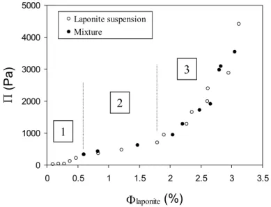
The inclusion of the probes did not shift the fluid/solid transition and did not modify the equation of state of laponite suspensions, as can be seen on Figure 7 which represents the osmotic pressure as a function of the volume fraction either with or without the probes, by analogy with the pressure-density isotherms for Van der Waals gases. This curve has been obtained by direct measurements of Π with a membrane osmometer for the lowest volume fractions and by osmotic compression (where Π is controlled by a solution of dextran) for the highest ones. For this latter experiment, the constant parameter is not Φprobes but the ratio Φprobes/Φlaponite. This ratio insures that Φprobes stays in the range 0.05% to 0.4% and the osmotic pressure of maghemite particles remains below 45 Pa (see part 1) which is much inferior to the one of laponite suspensions. Laponite particles thus determine the osmotic pressure of the hybrid system to preset values.
The pseudoplateau of the equation of state still exists for the composite dispersion. Neither its border nor its value were shifted. The three parts of the equation of state (before, along and after the pseudoplateau) will be denoted hereafter parts 1, 2 and 3 respectively. This result indicates that the inclusion of a few maghemite particles changes neither the interactions nor the structure of the system. These maghemite particles can be considered indeed as non-invasive probes.
0 1000 2000 3000 4000 5000 0 0.5 1 1.5 2 2.5 3 3.5 Φlaponite (%) (Pa ) Laponite suspension Mixture 1 2 3
Fig. 7: Experimental state isotherm curve Π vs. Φ for pure laponite suspensions in a Na3Cit solution (2.5 10-3 mol.L-1) at pH 10 (open dots) and for laponite doped with maghemite probes in the same chemical conditions (filled dots). The dotted lines separate the three characteristic domains of the equation of state considered in the text (before, along and after the pseudoplateau) [14].
C. Probing laponite gels heterogeneity, using magneto-optical probing and SANS
Particles have an intrinsic optical anisotropy, such that a CitMF become birefringent when submitted to a magnetic field as particles orientate along the field. The measurement of temporal birefringence relaxation after the application of a magnetic pulse (0.017 T) enables to measure a relaxation time τ of the probes, which is characteristic of their rotational diffusion. Knowing the diameter of the particles (from magnetic measurement) and using Stokes-Einstein relation, the viscosity of the mixture in the vicinity of the probes can be attained by such a measurement [9].
It appeared that this time τ is comparable for maghemite particles in water and in laponite whatever
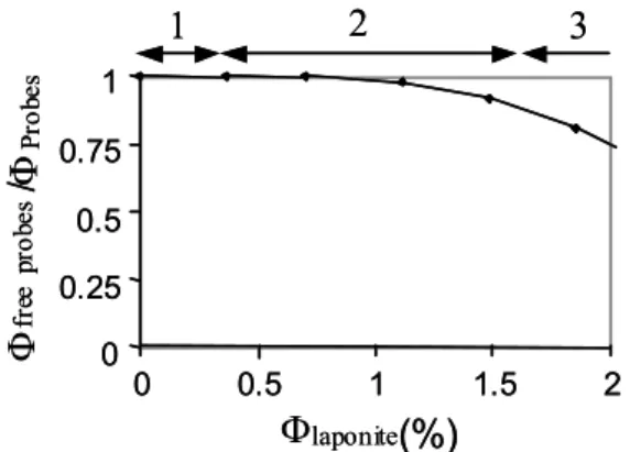
ΦLaponite, except for region 3 of the equation of state where τ is shorter. It shows that the particle’s dynamics is not slowed down in the region of the pseudoplateau even though suspensions are solid. In addition, no aggregates are formed, as they would increase the relaxation time. The ratio between birefringence in solid suspensions and in solution for the same volume fraction of maghemite particles gives the percentage of freely rotating particles at 0.017 T and is presented on Fig. 8. It departs
smoothly from 1 in the middle of the equation of state to reach 0.75 in region of equation 3. Thus some probes begin to be mechanically blocked only at the end of the pseudoplateau and become more and more numerous although laponite suspensions are solid since the beginning of the plateau. This result is in good accordance with the hypothesis of microscopic heterogeneities in laponite gels, liquid pockets coexisting with solid domains.
0 0.25 0.5 0.75 1 0 0.5 1 1.5 2
Φ
laponite(%)
Φ
fr ee pr ob es/Φ
Pr ob es1
2
3
0 0.25 0.5 0.75 1 0 0.5 1 1.5 2Φ
laponite(%)
Φ
fr ee pr ob es/Φ
Pr ob es1
2
3
Fig. 8: Ratio of the free maghemite probes in mixtures when increasing the volume fraction of laponite particles. The three domains correspond to the three regions of the equation of state [14].
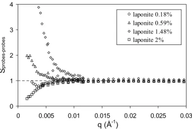
The spatial repartition of the maghemite probes is studied by SANS. In such an experiment, the solvent was a H2O/D2O mixture, which neutron scattering length density exactly matches the value of laponite particles. Indeed, the measured intensity only comes from the contribution of maghemite particles. The perfect extinction of laponite enables to get an effective structure of the probes. It is obtained by dividing absolute intensities by the form factor of the maghemite particles in dilute solution in pure solvent. The scattering vector ranged from 1.6 10-3 Å-1 to 3 10-2 Å-1. It appeared that at low ΦLaponite, the structure factor is close to one (part 1), indicating that the probes are homogeneously distributed. Along the pseudoplateau of the Π vs. ΦLaponite plot, the effective structure factor increases a lot with ΦLaponite at small q, revealing an increasing heterogeneity. This suggests that the probes are located in liquid-like pockets. In other words, they are excluded from the dense regions where Laponite particles are localized and share strong attractions. When ΦLaponite increases, the size of these large solid-like clay domains grows, while liquid pockets shrink and the effective structure factor increases further. For the largest ΦLaponite (part 3), the structure factor decreases again and even shows a pronounced depletion at low q. The probes are again homogenously dispersed with Laponite, but the presence of Laponite particles filling all the space prevent the probes from localizing and moving freely.
0 1 2 3 4 0 0.005 0.01 0.015 0.02 0.025 0.03 q (Å-1) Sprobes-probes laponite 0.18% laponite 0.59% laponite 1.48% laponite 2%
Fig. 9: Effective structure factor of magnetic probes in hybrid systems. Φprobes is constant (0.05%).
Φlaponite correspond respectively to part 1 of the equation of state (Φ = 0.18%), beginning (Φ = 0.59%) and end of part 2 (Φ = 1.48%), and part 3 (Φ = 2%) [14].
Thus SANS results are in agreement with local mechanical measurements and allow giving an illustration of the hybrid system for the different parts of the equation of state (Fig. 10). This was possible because first the chemical conditions of the mixture have been found and second because the presence of maghemite particles has not disturbed the equation of state of laponite.
1 2a 2b 3
1 2a 2b 3
Fig. 10: Schematic description of the laponite suspensions including magnetic probes (Φ = 0.05%). The small spheres represent the maghemite nanoparticles and the disks the laponite clay platelets. Picture (2a) and picture (2b) correspond respectively to the beginning and to the end of the pseudoplateau where solid-like domains of clay coexist with liquid-like pockets. Pictures (1) and (3) depict the pure liquid phase and the pure solid phase (gel) respectively [14].
IV. Ferrofluids and liposomes
“Magnetoliposomes” have been introduced by De Cuyper [39] to describe iron oxide nanoparticles wrapped by a lipid bilayer. Small and large magnetic liposomes have been studied during recent years for applications in the field of biotechnologies [40], because of their compatibility with biological media combined with their physical properties. In particular, their ability to move in a magnetic field gradient (a phenomenon called magnetophoresis) is useful for sorting processes. With a much larger size (10 µm and above), giant magnetoliposomes exhibit important deformations when a magnetic field is applied (Fig. 11). From the analysis of such shape modifications, it has been possible to get some information on the membrane properties. For example, the membrane bending modulus of the DOPC (1,2-dioleoyl-sn-glycero-3-phosphocholine) has been estimated [11].
a ) b)
Fig. 11: Magnetic field induced deformation of giant magnetoliposomes. Length of the bar is 10 µm. The field intensity is H=0 (a) and H=3 10-3 T (b). The arrow depicts the direction of the field.
A. CitMF: a good candidate for encapsulation
Several procedures are possible to encapsulate the nanoparticles in liposomes but two conditions are always required. The particles have to be negatively charged in order to avoid a quick adsorption of the phospholipid molecules on their surface and coated by citrate species in order to be dispersed in water at pH 7. The residual tri-sodium citrate in solution is sometimes a problem for applications, but its concentration can be adjusted through dialysis of the magnetic fluid against a tri-sodium citrate solution of the desired concentration.
Here the total osmotic pressure of the encapsulated magnetic fluid (osmotic pressure due to the particles + osmotic pressure due to the ionic species) is a key factor for the synthesis of the magnetoliposomes as for their stability. The problem is not a problem of phase diagram, because liposomes are out of equilibrium objects, but is related to the properties of the membrane and to the swelling of the liposomes. The ionic strength especially has to be carefully controlled because it will affect the properties of the final magnetoliposome.
B. Encapsulation of CitMF in giant liposomes
Particles can be introduced in the liposomes either by a multiple emulsion process [8], or by a spontaneous swelling in water of phospholipid bilayers filled with magnetic particles [47], or by the swelling of the phospholipidic bilayers in a magnetic fluid followed by the separation of the non encapsulated particles [41]. The procedure is chosen according to the size required for the final liposomes.
Giant unilamellar magnetic liposomes have been obtained by spontaneous swelling in water of phospholipid bilayers pre-hydrated with an aqueous magnetic fluid. The phospholipid powder (1 mg) is mixed with 10µL of CitMF and sheared on a glass support. Thus an oily orange film is obtained, which is then swollen with distilled water (1 mL) at 45°C.
The first remark is that the swelling is more efficient when the film is pre-hydrated by a solution of charged particles and ions rather than pure water. Indeed, the water added in excess to the multi-lamellar film swells the system in order to dilute the material entrapped in the phospholipid bilayers (the charged magnetic particles and the unadsorbed tri-sodium citrate). The low diffusion coefficient of the particles enables their encapsulation while the swelling process of the lipid bilayers takes place, whereas the tri-sodium citrate electrolyte diffuses rapidly in the surrounding medium.
If water is added under flow and in a restricted volume (for example directly in the observation chamber, 200 µm thickness) liposomes connected to tubes are observed (Fig. 12). Such phospholipidic tubes have soon been described [42]. The originality of the present system lies in the action of the magnetic fluid on the tube itself but also on the liposomes ending each tube. Pearling instability has thus been induced on such tubes by the stress of the two ending liposomes due to the application of a magnetic field [43].
Fig 12: Optical picture of the preparation obtained by spontaneous swelling of phospholpid bilayer stuffed with magnetic particles in water. The water is added under flow in the observation cell. Tube and liposome are linked together; the ferrofluid is inside the structure. The bar length is 20 µm.
The population of the liposomes obtained by spontaneous swelling is heterogeneous in size and in color, indicating that the concentration of magnetic particles is not the same in all liposomes. Because of the swelling process, these two characteristics cannot be calculated using a simple dilution factor, but both the volume fraction of magnetic particles and the concentration of tri-sodium citrate inside liposomes can be determined after all. Magnetophoresis experiments, i.e. migration in a controlled magnetic field gradient, allow an estimation of the volume fraction Φ of magnetic particles encapsulated inside the liposomes (ranging between 0.002 and 0.005%). The concentration of tri-sodium citrate encapsulated in the liposomes is obtained from the observation by optical microscopy of a liposome in a solution of known salinity. When the ionic strength is the same inside and outside the liposome, the latter appears as a sphere with a fluctuating membrane.
C. Deswelling of giant magnetoliposomes
Shape transitions are well-known consequences of an osmotic stress on red blood cells or on liposomes [44]. An increase of the osmotic pressure outside liposomes induces a decrease of their diameter that is related to the flow of water toward the outside of the liposomes across the lipid membrane. The same kind of phenomenon was observed with magnetoliposomes, the osmotic stress being induced by an increase of the salt concentration outside the liposomes [45]. Quantitative characterization of the deswelling process was performed by direct measurement of the vesicle radius as a function of time for different values of the concentration gradient across the phospholipid membrane (∆c) (Fig.13a). The permeability of the DOPC bilayer to water measured for ∆c ranging between 7 and 70 mmol.L-1 has been found equal to 34 µm/s in good agreement with the values found in other studies. It has to be underlined that all along the deswelling process, at the same time that the diameter of the liposomes decreases, the latter becomes more and more orange colored indicating an increase of its particle’s volume fraction. This indicates that the nanoparticles are unable to permeate the liposome surface, thereby suggesting the absence of mesoscopic pores during the osmotic stress inducing the deswelling process. Magnetic nanoparticles appear here as possible probes to test the formation of mesoscopic pores in a membrane. In most cases, the deswelling process leads to a drop of concentrated magnetic fluid stuck to a phospholipid membrane without any apparent release of magnetic material in solution. This drop exhibits an important deformation when a magnetic field of 0.03 Tesla is applied, attesting of the high concentration of magnetic material and of the presence of an excess of phospholipid membrane (Fig 14). Decreasing the osmotic pressure in the surrounding medium by water dilution, this object begins to swell again. In the end, a spherical liposome filled with the magnetic fluid is recovered, with almost the same size as before the osmotic stress (Fig 13b). The re-swelling process appears here as a proof that the membrane is not dramatically damaged during the deswelling process.
a)
b)
Fig 13: a) Optical microscopy of a magnetoliposome submitted to a concentration gradient ∆c=7 mmol.L-1. The diameter of the liposome decreases due to a water flow toward the outer medium. The bar length is 10 µm. b) Reswelling of a magnetoliposome that has been previously submitted to an osmotic stress.
Fig 14: Last stage of the osmotic stress. The inner phase becomes more and more contrasted and exhibits large deformation under a weak magnetic field (H=0.03 T).
D. Deformation of giant magnetoliposomes
An illustration of the importance of the encapsulated ferrofluid composition is the effect of the ionic strength upon the magnetic field induced deformations of liposomes. At high ionic strength, the application of a magnetic field of low intensity (0.04 Tesla) on a giant magnetoliposome elongates the latter in the direction of the field (prolate ellipsoid, Fig. 15a). Conversely at low ionic strength, the same magnetic field compresses the liposome at their poles (oblate ellipsoid, Fig. 15b). The relevant experimental parameters to explain this shape transition are the initial radius R0 of the liposome, the magnetic susceptiblity χ and the salt concentration Cs in the encapsulated ferrofluid. Two domains corresponding to both types of deformation are defined on a shape phase diagram, the oblate one being in the region of low values of R0, χ and Cs [46]. A model comparing the magnetic energy and the bending energy of the membrane enabled to establish the sensitivity of the shape on Cs [47]. The main result of this description is an anisotropic distribution of particles at the neighborhood of the
membrane when a magnetic field is applied. This shape transition triggered by the ionic strength is explained by an electrostatic interaction between the weakly charged phospholipid bilayer and the ionic encapsulated species (particles and Na3Cit electrolyte)
Fig. 15: Optical pictures of the two kinds of shape exhibited by a magnetolipsome under the application of a magnetic field [47]: a) prolate ellipsoid for a high ionic strength ferrofluide; b) oblate ellipsoid for a low ionic strength ferrofluid. Length of the bar is 10 µm.
E. Conclusion
This last part illustrates that the inclusion of a citrate-stabilized ferrofluid (CitMF) in liposomes allows probing some properties of the latter and helps for the interpretation of their behavior. Again the composition of the ferrofluid and especially the ionic strength is a key parameter as it controls the osmotic pressure of the systems. Giant liposomes are useful objects as they allow a direct observation of the effect of a physical control like the magnetic field, or a chemical modification of the system. For example mesoscopic pores or complete solubilization of the phospholipid membrane can be observed by addition of a detergent on giant magnetoliposomes. Once again the magnetic nanoparticles appear as possible probes. At a lower scale, small magnetoliposomes (LUV, 200 nm in diameter) are now under study. In this case, a direct observation is not possible and only averaged quantities can be determined. Nevertheless, they have applications in the field of pharmacology and a parallel between the behavior of the magnetic giant and large vesicles is interesting to make.
V. General conclusion
This paper illustrates through three examples the versatility of CitMF for making magnetic composite materials in aqueous media. The main interest of the specific magnetic properties of nanoparticles for the composite material was to perform mechanical measurements on the other component of the system on a large range of scales: macroscopic (stretching test for ferrogels and possibility of
magnetostriction), microscopic (deformation of giant liposomes under a magnetic field) and nanoscopic (local viscosity in laponite suspension).
The key point is the robustness of CitMF, which remains stable whatever the conditions of ionic strength and magnetic field in the pH stability range of nanoparticles. The perfect knowledge of interaction strength and range through osmotic pressure has allowed to set conditions of osmotic pressure for several purposes:
- For making stable ferrogels and tune their swelling and elastic properties through variation of the magnetic particle concentration.
- For using nanoparticles on an interaction range where they behave as non-invasive probes. - For exploring the swelling and deswelling of liposomes in response to an osmotic stress.
One may wonder about the possibility to dope with magnetic nanoparticles some composite materials that are not stable within the same physicochemical range than CitMF. Other chemical conditions of colloidal stability of such particles can be found by coating their surface with other ligands than citrate, surfactants [48], silica [49], or simply by using “naked” particles (bare iron oxide). Controlling the initial osmotic pressure of the precursor suspension of nanoparticles is still the prerequisite for ensuring the stability of the particles in the final product.
Acknowledgements
All these results have been obtained thanks to a close collaboration with Emmanuelle Dubois, Pierre Levitz, Régine Perzynski, Jean-Claude Bacri and Jean Chevalet. The part of this work about ferrogels is supported by CONACYT Mexico.
References
[1] Chaput F, Boilot J-P, Canva M, Brun A, Perzynski R, Zins D, 1993 J. Non-Cryst. Sol. 160 177-179 [2] Haas W, Zrínyi M, Kilian H.G., Heise B, 1993 Colloid. Polym. Sci. 271 1024-1034
[3] Mayer C, Cabuil V, Lalot T, Thouvenot R, 2000 Adv. Mater. 12 (6) 417
[4] Berejnov V, Raikher Yu, Cabuil V, Bacri J.C., Perzynski R, 1998 J. Colloid Interface Sci. 199 215 [5] Fabre P, Casagrande C, Veyssié M, Cabuil V, Massart R, 1990 Phys. Rev. Lett. 64 (5) 539
[6] Bibette J, 1993 J. Magn. Magn. Mat. 122 37
[7] Fermigier M, Gast A.P., 1993 J. Magn. Magn. Mat. 122 (1/3) 46 [8] Ménager C, Cabuil V, 1995 J. Coll. Interface Sci. 169 251

![Fig. 3: Swelling degree Q (filled circles) and particle’s release R (diamonds) versus sodium citrate concentration [Na 3 Cit] in the swelling bath for ferrogels prepared with a volume fraction of magnetic particles Φ 0 =3.8% and for undoped hydrogels (emp](https://thumb-eu.123doks.com/thumbv2/123doknet/13478982.413218/11.892.276.618.232.459/swelling-particle-diamonds-concentration-swelling-ferrogels-particles-hydrogels.webp)
![Fig. 4: Observation by optical microscopy of the gas-liquid like transition inside ferrogels prepared at an initial particle’s volume fraction Φ 0 = 3.8% and a cross-linking degree BA/AM=0.5% swollen in a salt concentration [Na 3 Cit]=0.25 mol.L -1 a) 9 h](https://thumb-eu.123doks.com/thumbv2/123doknet/13478982.413218/12.892.111.770.165.346/observation-microscopy-transition-ferrogels-prepared-particle-fraction-concentration.webp)

![Fig. 6: Final particle’s volume fraction in the swollen ferrogel Φ as a function of the tri-sodium citrate concentration [Na 3 Cit] in the swelling bath, computed from the measurements of Q and R represented on Fig](https://thumb-eu.123doks.com/thumbv2/123doknet/13478982.413218/16.892.272.625.477.749/particle-fraction-ferrogel-function-concentration-swelling-measurements-represented.webp)