HAL Id: hal-01389641
https://hal.archives-ouvertes.fr/hal-01389641
Submitted on 8 Dec 2016
HAL is a multi-disciplinary open access
archive for the deposit and dissemination of
sci-entific research documents, whether they are
pub-lished or not. The documents may come from
teaching and research institutions in France or
abroad, or from public or private research centers.
L’archive ouverte pluridisciplinaire HAL, est
destinée au dépôt et à la diffusion de documents
scientifiques de niveau recherche, publiés ou non,
émanant des établissements d’enseignement et de
recherche français ou étrangers, des laboratoires
publics ou privés.
Magnetic Field Models and their Application in Optimal
Magnetic Divertor Design
Maarten Blommaert, Martine Baelmans, Holger Heumann, Yannick
Marandet, Hugo Bufferand, N. R. Gauger, D. Reiter
To cite this version:
Maarten Blommaert, Martine Baelmans, Holger Heumann, Yannick Marandet, Hugo Bufferand, et al..
Magnetic Field Models and their Application in Optimal Magnetic Divertor Design. Contributions to
Plasma Physics, Wiley-VCH Verlag, 2016, �10.1002/ctpp.201610031�. �hal-01389641�
Magnetic Field Models and their Application in Optimal
Mag-netic Divertor Design
M. Blommaert⇤1, M. Baelmans2, H. Heumann3, Y. Marandet4, H. Bufferand4, N.R. Gauger5,
andD. Reiter1
1Institute of Energy and Climate Research (IEK-4), FZ J¨ulich GmbH, D-52425 J¨ulich, Germany 2KU Leuven, Department of Mechanical Engineering, 3001 Leuven, Belgium
3TEAM CASTOR, INRIA Sophia Antipolis, BP 93 06902 Sophia Antipolis, France 4Aix-Marseille Universit´e, CNRS, PIIM, F-13013 Marseille, France
5TU Kaiserslautern, Chair for Scientific Computing, 67663 Kaiserslautern, Germany
Key words Vacuum approach, magnetic equilibrium, divertor design, adjoint optimization, power deposition In recent automated design studies, optimal design methods were introduced to successfully reduce the often excessive heat loads that threaten the divertor target surface. To this end, divertor coils were controlled to im-prove the magnetic configuration. The divertor performance was then evaluated using a plasma edge transport code and a “vacuum approach” for magnetic field perturbations. Recent integration of a free boundary equilib-rium (FBE) solver allows to assess the validity of the vacuum approach. It is found that the absence of plasma response currents significantly limits the accuracy of the vacuum approach. Therefore, the optimal magnetic divertor design procedure is extended to incorporate full FBE solutions. The novel procedure is applied to ob-tain first results for the new WEST (Tungsten Environment in Steady-state Tokamak) divertor currently under construction in the Tore Supra tokamak at CEA (Commissariat `a l’Energie Atomique, France). The sensitivities and the related divertor optimization paths are strongly affected by the extension of the magnetic model.
Copyright line will be provided by the publisher
1 Introduction
At present, several plasma boundary codes exist that attempt to describe the complex interactions in the divertor SOL (Scrape-Off Layer) [1, 2, 3, 4]. The predictive capability of these edge codes at present is still very limited. Yet, in parallel to major efforts to mature edge codes, we face the design challenges for next step fusion devices. One of them is the design of the helium and heat exhaust system. Recently, automated design methods were introduced for the purpose of divertor design. While these were initially oriented to improve the shape of the divertor targets for more equal distribution of the target heat load [5], the methods were later applied to magnetic configuration design [6]. To this end, divertor coils were controlled to improve the magnetic configuration. Results of these studies indicated large potential reductions in peak heat load by an increased magnetic flux divergence towards the target structures [6, 7].
The model used to achieve these results combines a magnetic field model using the so-called “vacuum ap-proach” (VA) with a plasma edge transport model. In the VA it is assumed that magnetic field changes due to small coil perturbations can be sufficiently described by analyzing the effect of external coil changes in vacuum. The influence of altering plasma currents and their position is hereby neglected for the small changes concerned. Another application of the VA is to assess the effect of resonant magnetic perturbations [8].
Because of the rather large magnetic field changes that were found in past automated design studies, the legitimacy of the perturbation approach has to be questioned. Therefore, a MATLAB version of the CEDRES++ free boundary magnetic equilibrium (FBE) solver [9] was recently included into the simulation framework to improve the magnetic field model and its in parts adjoint sensitivities were validated [10]. The evident research question asked in this paper is if at all and under which conditions the VA is an acceptable substitute for the FBE model. Furthermore, the question arises how the optimal design is affected by this change in models.
2 M. Blommaert et al.: Magnetic Field Models for Optimal Divertor Design
The paper is structured as follows. In section 2, we analyze under which conditions the simplified pertur-bation approach is legitimate by comparing both models. Afterwards, the plasma edge transport model and the optimization approach are briefly outlined in section 3. Finally, first results are shown in section 4 for an opti-mized heat exhaust of the new WEST (Tungsten Environment in Steady-state Tokamak) divertor currently under construction in the Tore Supra tokamak at CEA (Commissariat `a l’Energie Atomique, France) [11, 12].
2 Poloidal magnetic flux models
2.1 Description of the magnetic flux models
The magnetic field in tokamaks is constituted by the coils around the vacuum chamber as well as the field induced by the plasma currents themselves. Considering a cylindrical coordinate system (R, , Z), the poloidal magnetic flux per radian is everywhere (in and outside the vacuum vessel) governed by the toroidal component of Amp`eres law r · ✓ 1 µRr ◆ = J , (1)
with J the current density in the toroidal direction and µ the relative magnetic permeability, which equals the permeability of vacuum µ0inside the vacuum vessel. In the domain ⌦pbounded by the last closed flux surface
(LCFS), the toroidal current density J can approximately be described by the Grad-Shafranov equation, which balances Lorentz force against plasma pressure [13]. Outside the LCFS, plasma currents are negligible, resulting in the free boundary equilibrium problem
J = 8 > < > : JP= Rp 0 ( ) + 1/(µ0R) FF 0 ( ) in ⌦p( ) , I /S in the coils, 0 anywhere else, (2) with p and F flux functions associated to the pressure and the R-scaled toroidal magnetic field component, respectively, and where the accent denotes a differentiation with respect to the poloidal flux . I represents the current in toroidal coils. The profiles p0
and FF0
are given in the form [14] p0( ) =
R0
(1 ¯↵) and FF0( ) = (1 )µ
0R0(1 ¯↵) , (3)
with ¯the normalized magnetic flux, which equals 0 at the magnetic axis (MA) and 1 at the LCFS. The physical meaning and choice of the profile parameters ↵, , is dealt with in [15]. is a scaling variable that assures that the total plasma current IP is kept constant. In the CEDRES++ framework, these equations are spatially
discretized using a first order finite element (FE) method and solved for using a Newton method. It is clear that the nonlinear dependence of the plasma boundary ⌦pon contributes to the complexity of this code. More
information can be found in [9].
The vacuum approach essentially assumes that in the linearization of the FBE solution = 0+ all
plasma currents changes JPcan be neglected at the one hand and, at the other, that the magnetic permeabilities
µ of surrounding materials can be approximated as µ0. The Biot-Savart law can then be used to calculate the
magnetic field. Moreover, if one assumes additionally that the conductors can be modelled as being of infinites-imal size, a semi-analytical expression for the poloidal magnetic flux change due to a single coil at location (r0, z0) is obtained [16]: (R, Z, r0, z0) = µ0R I ,ext k⇡ r r0 R ✓ 1 k 2 2 ◆ K(k) E(k) ,where (4) k2= 4Rr0 (R + r0)2+ (Z z0)2. (5)
I ,extis the additional external conductor current and K and E are complete elliptical integrals of the first and
second kind that can be evaluated fast numerically. It is obvious that the reduced complexity and increased speed are the main assets of this approach. The latter approach will be referred to as the perturbation model (PM).
2.2 Analysis of model assumptions
In this subsection, we show that the FBE model and PM are indeed equivalent if the assumptions introduced in the former section are made. As such, the correctness of implementation is verified and the effect of the different assumptions can be estimated. We demonstrate this using the reference equilibrium 0from the “far”
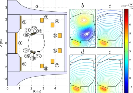
configuration of [17]. The WEST tokamak, for which the study in this paper is performed, is shown in figure 1a with coils, iron and the vacuum chamber clearly indicated. The divertor coils (numbered 10-19) will be of specific importance further on to control the magnetic configuration in the vacuum chamber. The reference magnetic equilibrium 0is obtained using the FBE code described in section 2.1, with ↵ = 1, = 1.5, = 0.9,
Ip = 0.47MA. The magnetic fields of both approaches will now be compared for an increase by 1 kA of all
lower divertor coils (coil numbers 14-17).
Fig. 1 a) The WEST machine. Coils are numbered and iron structures are indicated in light gray b-e) Close-up of the magnetic field change at a perturbation of 1kA of coils 14-17 at the vacuum vessel (black line) using: b) the FBE FE simulation, c) the FE simulation with JP = 0, d) the FE simulation with JP = 0and neglecting permeability of iron, e) PM (numerical evaluations of equations (4) and (5)).
Comparing the change in flux function = 0of the FBE model (figure 1b) with that of the PM (figure
1e) gives a significant difference. Especially in the core region of 1b, a clear difference in magnetic field is present that can be attributed to the absence of the nonlinear interaction with plasma currents in the PM. This can be confirmed by evaluating with the FE code for input parameters IP= 0and the coils loaded with a current
I (figure 1c), so that the additional plasma currents JPare put to zero. The comparison between FE code and
PM is now in better agreement. Removing the relative permeability of iron finally gives a good agreement of the FE code with the PM (figure 1d). The local effect of supposing infinitesimal coil currents for the PM can be clearly seen when comparing (figure 1d) and (figure 1e), but the latter assumption has almost no consequence on the magnetic field in the vacuum chamber.
2.3 Comparison of sensitivities
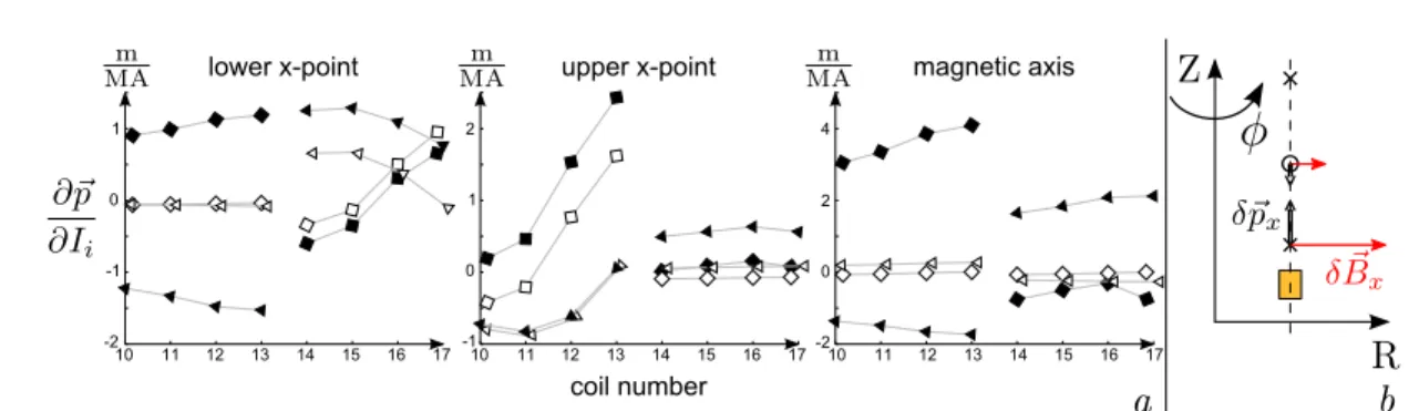
Next, we compare the first order behavior of the stationary points of for both models. Indeed, X-points are an important characteristic of the magnetic field. The sensitivities @~p/@' of the movement of such a point with respect to the coil current magnitudes is found by using a simple forward finite difference approach on both magnetic models, where the perturbation size k 'k = ✏1/3
m is linked to the machine precision ✏m, ~p =
R eR+ Z eZis the position vector in the poloidal plane and 'i= I ,i/Ic = I ,i (105A) are the dimensionless
4 M. Blommaert et al.: Magnetic Field Models for Optimal Divertor Design
Fig. 2 a) Comparison of the sensitivities of the lower and upper X-point and MA positions with respect to the divertor coil currents (FBE: plain symbols, PM: empty symbols, R-component: squares, Z-component: triangles). Coil numbers as given in figure 1. b) Simplified analysis of the movements in the VA. The magnetic field change at the X-point due to a positive coil perturbation I is shown in red and the corresponding movement of the X-point with a double arrow.
The results of this study are shown in figure 2. Remark that overall, big discrepancies are found in the sen-sitivity analysis and that both models sometimes even have sensen-sitivity contributions of opposite sign. However, reasonable agreement is found for the sensitivities of the lower X-point with respect to coils 14-17 and those of the upper X-point with respect to coils 10-13. This is a logical consequence of the fact that these coils are in the direct vicinity of these respective X-points under consideration. The magnetic field caused by a current decreases approximately with the squared distance from the current source, so that close enough to the coils the effect of the coil current dominates that of the plasma currents.
We now illustrate the discrepancies between the models with a simple example. Suppose that X-points, MA and a divertor coil are aligned as illustrated in figure 2b. One can then study the first order effect of plasma currents on the X-point location. The displacement ~p = [ pR, pZ]>of a stationary point in can be obtained
by linearizing the spatial derivative of around the stationary point location ~p = ~p0with respect to ~p,
@ @~p = @ @~p p~0+ @2 @~p2 ~ p0 ~p and thus ~p = @2 @~p2 ~ p0 ! 1 @ @~p ~p0, (6)
where the latter equality holds because @ /@~p ⌘ 0 at a stationary point of . The X-point movement caused by a small change in coil current I (in positive ˆ direction) is then given by
@~p @I = @2 @~p2 ~ p0 ! 1 @2 @~p @I ~p0,with @2 @~p @I = R@BZ @I , R @BR @I > (7) and where ~B = BReR+ B e + BZeZ is the magnetic flux density. The Hessian matrices, with respect to
R and Z, Hx = @2 @~p2 ~p
x at the X-points and Hma = @
2 @~p2 ~
pma at the MA ~pma are in this case of
the form Hx=diag ( a1, a2)and Hma=diag ( a3, a4), respectively, with coefficients a1, a2, a3, a42 R+.
The well-known right hand rule can be used to find the direction of @ ~B/@I I at the lower X-point caused by a positive perturbation I1. Hence, equation (7) retrieves an upwards movement ~p
x= @ ~px/@I Iof the lower
X-point. If one involves the plasma current IP, the conclusion is less straightforward. Suppose the plasma currents
can be represented using a single coil tied to the MA. The movement of the MA and therefore that of the plasma current can then be analyzed using equation (7). One finds that the MA moves in the opposite direction of the X-point (downwards) and thus creates a counteracting magnetic field at the lower X-point. The direction of the X-point movement now depends on the current IP, the mutual distances of the variables and the coefficients a2
and a4. The resulting movement direction becomes less predictable because of this indirect effect.
Looking again at figure 2, one sees that this simplified analysis without plasma current indeed shows the right tendency for coils 14-17 of the lower X-point and for coils 10-13 at the upper X-point for the PM. One also sees that all other sensitivities using the PM are relatively close to zero because of the large distance between coil and
stationary point. One may thus conclude that in those cases, the indirect effect of the plasma currents dominates, since the plasma currents are closer to those stationary points then the perturbed coil. Finally, it appears from figure 2 that the movement of the MA in the FBE model is not correctly predicted by the simplified analysis, since the reduction of the plasma currents to a coil at the MA is not a good approximation. Although further examination of alternative perturbative models with preprocessed determination of the plasma current “gravity center” are possible, the authors have decided to incorporate the FBE model in the optimal design approach.
3 Optimal magnetic divertor design
The FBE model for magnetic flux simulation is combined with a plasma edge grid generator and plasma edge transport code for optimization of the target heat load in an optimal design approach. The plasma edge model can be found in [6] and features ion continuity and momentum conservation, a neutral pressure diffusion equation, and an internal energy equation, solved for a combined ion-electron-neutral temperature T . The aim is to avoid heat peaks at the target surface, by minimizing the objective functional
ˆ I (') = 12 Q Z St (Q?(') Qd,t)2d + 1 2 '' >' (8)
using the dimensionless coil currents ', where the surface integral with elementary surface vector d integrates over the target surface area St. Q?is the heat flux density perpendicular to the target surface and Qd,ta desirable
spatially constant heat flux profile. The second term is a Tikhonov regularization term, which physically penalizes excessive Joule losses. Qand 'are both a normalization and a weighting factor for their corresponding terms.
Furthermore, the optimization is augmented with design constraints of the form ˆh(') 0. Constraints are imposed on the coil currents to represent the conductor and current source limits. Additionally, a minimal distance is set between X-point and target surface to guarantee the existence of a divertor configuration and avoid excessive flux of impurities to the core region. Other constraints are imposed but are not discussed, since they do not influence the results presented in section 4. The optimization is then solved using gradient based descent, where the sensitivities of the objective functional with respect to the coil currents @'I are calculated using anˆ
in parts adjoint method presented in [7] and elaborated and verified for the FBE model in [10]. The sequential quadratical programming method used for optimization is discussed in [6].
4 Results and discussion
The optimization algorithm is used to find an improved magnetic configuration of the WEST configuration pre-sented earlier in section 2.2, by making use of the coil currents in coils 10-17 (see figure 1a)2. A core input
power of 7.93 MW is imposed together with a fixed density at the core boundary of 2.7 · 1019m 3. For further
information about plasma edge transport parameters and boundary conditions we refer to [10], were the same set-up was used. The optimization algorithm was stopped when it settled after five optimization cycles. More-over, 92% of the changes in cost functional was realized in the first two cycles. The entire optimization came at the cost of roughly twelve plasma edge simulation equivalents, with free boundary equilibrium calculation and grid generation cost negligible to that of a plasma edge simulation. Remark that this can be easily reduced to six plasma edge simulation equivalents for practical design purposes.
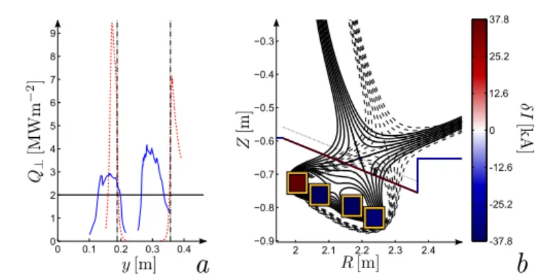
In figure 3 a and b, the heat load and magnetic field change resulting from the optimization are given, respec-tively. It is observed in figure 3a that the peak heat load is reduced by 56% and in 3b that this is realized by a significantly enlarged projected area through flux expansion. The latter effect on the heat load clearly dominates the effect of the reduced connection length in the current plasma regime. Note that a detached configuration might hold a different balance between these two means to spread the heat flux. Moreover, the total coil current was reduced by 94 kA. Nevertheless, the current in coil 14 was increased to 75 kA to accommodate for the large flux expansion. The increase and decrease of neighbouring coils 14 and 15, respectively, has a clear similarity with the X-divertor [18] in the way the flux expansion is realized.
The optimization was also repeated with the perturbation model. A similar tendency was found there. Again, the movement of the X-point towards the target accompanied flux expansion and a decreased heat load. Yet, the
6 M. Blommaert et al.: Magnetic Field Models for Optimal Divertor Design
Fig. 3 a) Heat load profile on the target surface in comparison to the desired profile Qd, before (dotted) and after optimization (solid line). b) Close-up of the magnetic configuration change at the divertor region from initial (dashed) to optimized (solid). The colorbar indicates the change in current magnitudes I. The dotted line represents the design constraint.
optimal currents were different and changes in currents had to be significantly larger to realize a similar change in magnetic configuration. Due to the design constraints on the current sizes, the peak heat load was only reduced by 34 % in the optimal configuration. We conclude that by ignoring plasma currents, the perturbation model significantly underestimates the effect coil currents can have on the magnetic configuration.
5 Conclusion
In the comparative study of a perturbation model with VA and a full FBE model to simulate the magnetic flux function, it is found that the use of the perturbation model only gives a reasonable estimation of the poloidal magnetic flux in the divertor region in the direct vicinity of the divertor coils. In a first optimal magnetic divertor design study that incorporates the FBE solver, significantly different optimal currents were found. The integration of a FBE solver is therefore indispensable for realistic magnetic field design. In ongoing work, we attempt to maximize the heat load under a restricted target temperature. Thus, we aim to assist the WEST project, which attempts to create circumstances similar to those of the future ITER tests. In first trials it was found that a direct maximization of the objective functional used in this paper induces a physically irrelevant maximum. Model assumptions and objective functional will therefore have to be revised to achieve the former goal.
Acknowledgements We are grateful to Eric Nardon for his valuable assistance to set up the WEST equilibrium calculations.
References
[1] D. Reiter, M. Baelmans, and P. B¨orner, Fusion Science and Technology47(Feb), 172–186 (2005). [2] D. Stotler et al., Contrib. Plasma Phys.40(3-4), 221–226 (2000).
[3] H. Bufferand et al., Nuclear Fusion55(5), 053025 (2015). [4] R. Simonini et al., Contrib. Plasma Phys.34(2-3), 368–373 (1994).
[5] W. Dekeyser, D. Reiter, and M. Baelmans, Nuclear Fusion54(7), 073022 (2014). [6] M. Blommaert et al., Nuclear Fusion55(013001) (2015).
[7] M. Blommaert et al., Journal of Nuclear Materials463(0), 1220–1224 (2015). [8] T. Lunt et al., Nuclear Fusion52(5), 054013 (2012).
[9] H. Heumann et al., Journal of Plasma Physics81(03), 1469–7807 (2015).
[10] M. Blommaert et al., ESAIM: Proceedings and Surveys (2015), accepted for publication. [11] J. Bucalossi et al., Fusion Engineering and Design89(7–8), 907–912 (2014).
[12] C. Bourdelle et al., Nuclear Fusion55(6), 063017 (2015). [13] V. D. Shafranov, Reviews of Plasma Physics2, 103 (1966). [14] J. Luxon and B. Brown, Nuclear Fusion22(6), 813 (1982).
[15] J. Blum, Numerical simulation and optimal control in plasma physics (Wiley/Gauthier-Villars, 1989).
[16] Y. N. Dnestrovskii and D. P. Kostomarov, Controlled Fusion and Numerical Simulation, in: Springer Series in Compu-tational Physics, (Springer Berlin Heidelberg, 1986), pp. 1–28.
[17] H. Bufferand et al., Contrib. Plasma Phys.54(4-6), 378–382 (2014).