Filière Systèmes industriels
Orientation Power & Control
Diplôme 2015
Joseph Rigaud
Efficience et suivi énergétique d’un hôtel isolé
du réseau électrique
Professeur
J e s s e n P a g e
Expert
W er n e r F is c h e r
Date de la remise du rapport
1 0 . 0 7 . 2 0 1 5
Objectif du projet
Réduire les 20'000 litres de mazout consommé par le chauffage et la génératrice de l’hôtel Weisshorn chaque hiver en mettant en place des mesures d’efficacité. Le second objectif de ce travail est l’installation d’une supervision locale et distante pour assurer un suivi de l’hôtel.
Méthodes | Expérie nces | R ésultats
Dans un premier temps un état des lieux de l’hôtel a été fait afin d’en connaître tous les aménagements existants. Ensuite deux analyses ont été réalisées successivement. Premièrement une étude qui porte sur la partie électrique de l’hôtel pour identifier et tracer le profil de puissance journalier, les principaux consommateurs et le mode de fonctionnement des installations principales. Des premières propositions d’amélioration ont alors été proposées pour économiser des litres de mazout utilisé par le groupe électrogène. La seconde étude est orientée sur la partie thermique du bâtiment, à savoir le système de chauffage et de ventilation pour économiser des litres de mazout utilisé par le brûleur. Plusieurs alternatives d’amélioration ont été étudiées et les moins coûteuses ont été retenues.
La seconde partie du travail portait sur la réalisation d’une supervision locale et distante de l’hôtel exploitant les mesures existantes et quelques nouvelles mesures installées. Cette supervision doit satisfaire les attentes du gérant et du propriétaire et permettre un suivi effectif.
Finalement les mesures entreprises du côté électrique et thermique ont permis de réduire fortement la consommation de mazout de l’hôtel. La visualisation distante en temps réel accompagné d’archivage des données et d’e-mails d’alarme automatiques permettent le suivi effectif de cet hôtel situé à 2337 m d’altitude.
Efficience et suivi énergétique d’un hôtel isolé du
réseau électrique
Dip lômant/e
Joseph Rigaud
Trava il de dip lôme
| é d i t i o n 2 0 1 5 |
Filière
Systèmes industriels Domaine d’application Power & Control
Professeur responsable Jessen Page
Jessen.page@hevs.ch
Partenaire RD Carbon
Projektzie le
Senkung des Oelverbrauches des Hotel Weisshorn unm 50% (12’000l) bei spezifischen Kosten von weniger als 5 frs/l
Echtzeit Visualisation des thermischen und elektrischen Betriebsparameter
Methoden | Ana lysen | Resu ltate
Analyse des thermischen und elektrischen Istzustandes pro Woche und Tag
Definition des Sollzustandes
Tagesbetrieb mit Dieselgenerator Nachtbetrieb mit Wasserturbine
Evaluation aller technischen Möglichkeiten und Realisation der Wirtschaftlichen
Ergebnis :
Senkung des Oelverbrauches um 13'000 l Oel/Jahr (40'000 kg CO2/Jahr)
Investitionen : 54'000 frs, Payback time weniger als 4 Jahre Echtzeitvisualisation der Betriebsparameter funktionel
Energieeffizienz und Überwachung von einem
Hotel isoliert vom Netz
Dip lômant/e
Joseph Rigaud
Dip lomarbeit
| é d i t i o n 2 0 1 5 |
Filière Systèmes industriels Domaine d’application Power & ControlProfesseur responsable Jessen Page
Jessen.page@hevs.ch
Partenaire RD Carbon
0 5 10 15 20 25 18.08.2014 19.08.2014 20.08.2014 21.08.2014 22.08.2014 23.08.2014 24.08.2014 25.08.2014 [k W ]Turbine Generatrice Total moyenne 1h
0 5 10 15 20 25 18.08.2014 19.08.2014 20.08.2014 21.08.2014 22.08.2014 23.08.2014 24.08.2014 25.08.2014 [k W ]
0 5 10 15 20 25 16.03.2014 17.03.2014 18.03.2014 19.03.2014 20.03.2014 21.03.2014 22.03.2014 [k W ]
Turbine Generatrice Total moyenne 1h
0 2 4 6 8 10 12 14 16 18 20 16.03.2014 17.03.2014 18.03.2014 19.03.2014 20.03.2014 21.03.2014 22.03.2014 [k W ] Production turbine
𝐸
é𝑙𝑒𝑐𝑟𝑖𝑞𝑢𝑒= 𝑃 ∙ 𝑡
𝐸
é𝑙𝑒𝑐𝑡𝑟𝑖𝑞𝑢𝑒= 120 𝑗 ∙ 24 ℎ ∙ 9 𝑘𝑊 = 26
′000 𝑘𝑊ℎ
𝐸
é𝑙𝑒𝑐𝑡𝑟𝑖𝑞𝑢𝑒= ∫
𝑃(𝑡) 𝑑𝑡 = 11
′000 𝑘𝑊ℎ
𝑎𝑣𝑟𝑖𝑙 𝑗𝑎𝑛𝑣𝑖𝑒𝑟𝜂
𝑔é𝑛é𝑟𝑎𝑡𝑟𝑖𝑐𝑒= ∙
𝐸
é𝑙𝑒𝑐𝑡𝑟𝑖𝑞𝑢𝑒𝑉 ∙ 𝑃𝐶𝑖
𝑑𝑖𝑒𝑠𝑒𝑙=
𝐸
é𝑙𝑒𝑐𝑡𝑟𝑖𝑞𝑢𝑒5000 𝑙 ∙ 10
𝑘𝑊ℎ
𝑙
=
11
′000
50
′000
= 22 %
𝐸
𝑡𝑜𝑡𝑎𝑙_ é𝑙𝑒𝑐𝑡𝑟𝑖𝑞𝑢𝑒= 𝐸
𝑡𝑢𝑟𝑏𝑖𝑛𝑒+ 𝐸
𝑔é𝑛é𝑟𝑎𝑡𝑟𝑖𝑐𝑒= 37
′000 𝑘𝑊ℎ
𝑃
𝑚𝑜𝑦𝑒𝑛𝑛𝑒_é𝑙𝑒𝑐𝑡𝑟𝑖𝑞𝑢𝑒=
𝐸
𝑡𝑜𝑡𝑎𝑙_ é𝑙𝑒𝑐𝑡𝑟𝑖𝑞𝑢𝑒120 𝑗 ∙ 24 ℎ
= 12.8 𝑘𝑊
𝐸 = 𝑃
𝑛𝑢𝑖𝑡∙ 𝑡 = 5 𝑘𝑊 ∙ 8ℎ ∙ 12𝑠𝑒𝑚 ∙ 7𝑗 = 3360 𝑘𝑊ℎ =
1527 𝑙
𝑑𝑖𝑒𝑠𝑒𝑙𝐸 = 𝑃
𝑠𝑢𝑝𝑝∙ 𝑡 = 5 𝑘𝑊 ∙ 16ℎ ∙ 12𝑠𝑒𝑚 ∙ 7𝑗 = 6720 𝑘𝑊ℎ =
840 𝑙
𝑚𝑎𝑧𝑜𝑢𝑡𝐸 = 𝑃
𝑠𝑢𝑝𝑝∙ 𝑡 = 5 𝑘𝑊 ∙ 24ℎ ∙ 5𝑠𝑒𝑚 ∙ 7𝑗 = 4200 𝑘𝑊ℎ =
525 𝑙
𝑚𝑎𝑧𝑜𝑢𝑡
𝐸 = 𝑃
𝑛𝑢𝑖𝑡∙ 𝑡 = 5 𝑘𝑊 ∙ 8ℎ ∙ 5 𝑠𝑒𝑚 ∙ 7𝑗 = 1400 𝑘𝑊ℎ =
636 𝑙
𝑑𝑖𝑒𝑠𝑒𝑙 0 5 10 15 20 25 30 35décembre janvier février mars avril mai juin
d éb it [l /s ] Mois
𝑐𝑜𝑛𝑠𝑜𝑚𝑚𝑎𝑡𝑖𝑜𝑛
𝑎𝑣𝑎𝑛𝑡=
1
𝑃𝐶𝑖
𝑑𝑖𝑒𝑠𝑒𝑙∙ 𝜂
1=
1
10
𝑘𝑊ℎ
𝑙 ∙ 17.5%
= 0.57
𝑙
𝑘𝑊ℎ
𝑐𝑜𝑛𝑠𝑜𝑚𝑚𝑎𝑡𝑖𝑜𝑛
𝑎𝑝𝑟è𝑠=
1
𝑃𝐶𝑖
𝑑𝑖𝑒𝑠𝑒𝑙∙ 𝜂
2=
1
10
𝑘𝑊ℎ
𝑙 ∙ 22%
= 0.45
𝑙
𝑘𝑊ℎ
gain = 11 𝑀𝑊ℎ ∙ (0.57 − 0.45)
𝑙
𝑘𝑊ℎ
=
1320 𝑙
𝑑𝑖𝑒𝑠𝑒𝑙Gr.1
Gr.2
Gr.3
Génératrice
Turbine
Gr.0
Groupe 0 16% Groupe 1 49% Groupe 2 32% Groupe 3 3% Groupe 0 Groupe 1 Groupe 2 Groupe 3 0 2 4 6 8 10 12 14 16 18 1 2 3 4 5 6 7 8 9 10 11 12 13 14 15 16 17 18 19 20 21 22 23 24 Pmo yenn e [ kW ] heure [h] Groupe 3 Groupe 2 Groupe 1 Groupe 0 Max Turbine
chambres froides 22%
pompe eau potable 16%
lave-vaisselle 11% chaufferie 7% bain-marie 7% prises cuisine 6% ventilation 6% prises bar 4% dépendance 3% lave-verre 3% fabrication de froid 24%
pompe eau potable 16%
vaisselle 14% prises 11% cuisson 7% chaufferie 7% lumière 7% ventilation 6% buanderie 5% dépendance 3%
𝐸 = 𝑃 ∙ 𝑡 = 1𝑘𝑊 ∙ 8ℎ ∙ 120𝑗 = 960 𝑘𝑊ℎ =
120 𝑙
𝑚𝑎𝑧𝑜𝑢𝑡
𝐸 = 𝑃 ∙ 𝑡 = 3 𝑘𝑊 ∙ 2ℎ ∙ 120𝑗 = 720 𝑘𝑊ℎ =
327 𝑙
𝑑𝑖𝑒𝑠𝑒𝑙𝐸 = 𝑃 ∙ 𝑡 = −3 𝑘𝑊 ∙ 2ℎ ∙ 120𝑗 = −720 𝑘𝑊ℎ =
−90 𝑙
𝑚𝑎𝑧𝑜𝑢𝑡
Gr.1 Génératrice Turbine Gr.2 Gr.3 AUTO 0 SECOURSGroupe X sur génératrice
P turbine> P hôtel ?
Groupe X sur turbine
Tension turbine OK ?
vrai pendant 15 min consécutive
faux
faux
vrai
Génératrice ON
Aucun groupe sur génératrice ? Génératrice OFF Tension turbine OK ? faux faux vrai Ordre priorité de groupes:
X := 1 2 3
vrai pendant 15 min consécutive
𝑇
1= 𝑇
𝑚𝑜𝑦𝑒𝑛𝑛𝑒 𝐶𝐹=
𝑇
𝑐𝑜𝑛𝑔é𝑙𝑎𝑡𝑒𝑢𝑟+ 𝑇
𝑓𝑟𝑖𝑔𝑜2
=
−19°𝐶 + 4°𝐶
2
= −7.5 °𝐶
𝑇
2= 𝑇
𝑚𝑜𝑦𝑒𝑛𝑛𝑒 𝑒𝑥𝑡é𝑟𝑖𝑒𝑢𝑟= −3.5°𝐶
𝑇
3= 𝑇
𝑎𝑚𝑏𝑖𝑎𝑛𝑡 ℎô𝑡𝑒𝑙= 20°𝐶
𝛥𝑇
𝐴= 𝛥
𝑎𝑐𝑡𝑢𝑒𝑙= 𝑇
3− 𝑇
1= 20°𝐶 − (−7.5°𝐶) = 27.5°𝐶
𝛥𝑇
𝐵= 𝛥
𝑓𝑢𝑡𝑢𝑟= 𝑇
2− 𝑇
1= −3.5°𝐶 − (−7.5°𝐶) = 4°𝐶
𝐸
𝐶𝐹 𝐴= 22% ∙ 1500
𝑘𝑊ℎ
7 𝑗
∙ 120 𝑗 = 5657 𝑘𝑊ℎ
𝐸
𝐶𝐹 𝐵=
𝐸
𝐶𝐹 𝐴𝛥𝑇
𝐴∙ 𝛥𝑇
𝐵=
5657𝑘𝑊ℎ
27.5°𝐶
∙ 4°𝐶 = 822 𝑘𝑊ℎ
𝑔𝑎𝑖𝑛
𝑡𝑜𝑡𝑎𝑙= 𝐸
𝐶𝐹 𝐴− 𝐸
𝐶𝐹 𝐵= 5675 𝑘𝑊ℎ − 825 𝑘𝑊ℎ = 4834 𝑘𝑊ℎ
𝑔𝑎𝑖𝑛
𝑑𝑖𝑒𝑠𝑒𝑙=
𝑔𝑎𝑖𝑛
𝑡𝑜𝑡𝑎𝑙2
= 2417 𝑘𝑊ℎ =
1098 𝑙
𝑑𝑖𝑒𝑠𝑒𝑙𝑔𝑎𝑖𝑛
𝑚𝑎𝑧𝑜𝑢𝑡=
𝑔𝑎𝑖𝑛
𝑡𝑜𝑡𝑎𝑙2
= 2417 𝑘𝑊ℎ =
302 𝑙
𝑚𝑎𝑧𝑜𝑢𝑡𝐸 = 7% ∙ 1500
𝑘𝑊ℎ
7 𝑗
∙ 120 𝑗 = 1800 𝑘𝑊ℎ =
818 𝑙
𝑑𝑖𝑒𝑠𝑒𝑙
𝐸 = 5% ∙ 1500
𝑘𝑊ℎ
7 𝑗
∙ 60 𝑗 = 642 𝑘𝑊ℎ =
292 𝑙
𝑑𝑖𝑒𝑠𝑒𝑙𝐸 = 5% ∙ 1500
𝑘𝑊ℎ
7 𝑗
∙ 60 𝑗 = 642 𝑘𝑊ℎ =
80 𝑙
𝑚𝑎𝑧𝑜𝑢𝑡𝐴
1 (𝑐𝑜𝑛𝑑𝑢𝑖𝑡𝑒 𝑓𝑜𝑟𝑐é𝑒)=
𝜋 ∙ 𝑑
24
=
𝜋 ∙ 0.15
24
= 0.018 𝑚
2𝐴
2 (𝑚𝑎𝑥𝑖𝑚𝑢𝑚 𝑖𝑛𝑗𝑒𝑐𝑡𝑒𝑢𝑟𝑠)= ∑
𝜋 ∙ 𝑑
𝑖 24
6 𝑖=1= 0.001 𝑚
2𝑐 = √2 ∙ 𝑔 ∙ ℎ = √2 ∙ 9.81 ∙ 120 = 48.5
𝑚
𝑠
𝐴
1∙ 𝑐
1= 𝐴
2∙ 𝑐
2= 2.8
𝑚
𝑠
𝑝 + 𝜌
𝑒𝑎𝑢∙ 𝑔 ∙ ℎ
⏟
pression statique+
𝜌 ∙
𝑐
122
⏟
pression dynamique= 𝑐𝑜𝑛𝑠𝑡
𝜌
𝑒𝑎𝑢∙ 𝑔 ∙ ℎ = 1000
𝑘𝑔
𝑚
3∙ 9.81 ∙ 120 𝑚 = 11.77 𝑏𝑎𝑟
ρ ∙
𝑐
1 22
= 1000
𝑘𝑔
𝑚
3∙
2.8
22
= 0.04 𝑏𝑎𝑟
0 5 10 15 20 25 30 35 0 200 400 600 800 1000 1200 P [kW] surface d'injecteurs [mm2] 0 2 4 6 8 10 12 14 16 10.2 10.4 10.6 10.8 11.0 11.2 11.4 11.6 11.8 12.0 0 5 10 15 20 25 30 35 40 p ert es d e c h arg e [m] p [b ar ] débit [l/s]
0 5 10 15 20 25 30 35 0 5 10 15 20 25 30 35 40 P [kW] débit [l/s]
0 0.5 1 1.5 2 2.5 3 0 5 10 15 20 25 30 Pe rte s lig n e 10 00 V [k W ] P turbine [kW] 0 0.5 1 1.5 2 2.5 3 0 1 2 3 4 5 6 7 8 Ré acti f l ig n e 10 00 V [k var ] Q turbine [kvar]
𝐸
𝑖𝑛𝑡𝑒𝑟𝑠𝑎𝑖𝑠𝑜𝑛= 𝑃
𝑠𝑢𝑟𝑝𝑙𝑢𝑠_𝑚𝑜𝑦∙ 𝑡 = 7.5 𝑘𝑊 ∙ 24ℎ ∙ 60𝑗𝑜𝑢𝑟𝑠 = 10.8 𝑀𝑊ℎ
𝐸
𝑏𝑎𝑡𝑡𝑒𝑟𝑖𝑒= 𝑈 ∙ 𝐴ℎ = 12 𝑉 ∙ 225 𝐴ℎ = 2.7 𝑘𝑊ℎ
0 5 10 15 20 25 30 novembre décembre P [kW]𝑛
𝑏𝑎𝑡𝑡𝑒𝑟𝑖𝑒=
𝐸
𝑖𝑛𝑡𝑒𝑟𝑠𝑎𝑖𝑠𝑜𝑛𝐸
𝑏𝑎𝑡𝑡𝑒𝑟𝑖𝑒=
10.8 𝑀𝑊ℎ
2.7 𝑘𝑊ℎ
= 4000 𝑏𝑎𝑡𝑡𝑒𝑟𝑖𝑒𝑠
𝑝𝑟𝑖𝑥 𝑡𝑜𝑡𝑎𝑙𝑒 = 𝑛
𝑏𝑎𝑡𝑡𝑒𝑟𝑖𝑒∙ 300 𝑓𝑟𝑠 = 1,2 𝑚𝑖𝑙𝑙𝑖𝑜𝑛𝑠 𝑓𝑟𝑠
𝑄 = 𝑚 ∙ 𝑐 ∙ ∆𝑇 → 𝑚 =
𝑄
𝑖𝑛𝑡𝑒𝑟𝑠𝑎𝑖𝑠𝑜𝑛(𝑐 ∙ ∆𝑇)
0 100 200 300 400 500 600 700 800 900 1'000 0 10 20 30 40 50 60 70 80 90 eau [l m3] ΔT
𝑉
𝑏𝑎𝑟𝑟𝑎𝑔𝑒= 𝑃
𝑠𝑢𝑟𝑝𝑙𝑢𝑠_𝑚𝑜𝑦∙ 1
𝑙𝑖𝑡𝑟𝑒
𝑠 ∙ 𝑘𝑊
∙ 3600𝑠 ∙ 24ℎ ∙ 60 𝑗 =
𝑉
𝑏𝑎𝑟𝑟𝑎𝑔𝑒= 7.5 𝑘𝑊 ∙ 0.001
𝑚
3
-20 -15 -10 -5 0 5 10 15décembre 2014 janvier 2015 février 2015 mars 2015 avril 2015
te m p ératu re air a m b ian t [° C] temps
47.7 31.7 30.2 24.3 20.7 3.8 3.6 0 10 20 30 40 50 60toilettes douche machine à laver cuisson soins corporels autres lave-vaisselle eau [l itr es ]
𝑄
𝑠𝑎𝑖𝑠𝑜𝑛= 𝑚̇
𝑒𝑎𝑢∙ 𝑡 ∙ 𝑛
𝑛𝑢𝑖𝑡é𝑒𝑠∙ 𝑐
𝑒𝑎𝑢∙ ∆𝑇 =
𝑄
𝑠𝑎𝑖𝑠𝑜𝑛= 60
𝑙𝑖𝑡𝑟𝑒𝑠
𝑗𝑜𝑢𝑟
∙ 120 𝑗𝑜𝑢𝑟𝑠 ∙ 10 𝑛𝑢𝑖𝑡é𝑒𝑠 ∙ 4187
𝐽
𝑘𝑔
∙ (20 − 5)°𝐶 =
𝑄
𝑠𝑎𝑖𝑠𝑜𝑛= 4522 𝑀𝐽 = 1256 𝑘𝑊ℎ = 157 𝑙𝑡 𝑚𝑎𝑧𝑜𝑢𝑡
AIR VICIÉ PULSION RESTAURANT AIR NEUF EXTRACTION CUISINE PRÉCHAUFFAGE CHAUFFAGE FILTRE FILTRE in °C out °C𝑃
𝑑é𝑝𝑒𝑟𝑑𝑖𝑡𝑖𝑜𝑛= 𝑚̇ ∙ 𝑐 ∙ ∆𝑇 = 𝑞𝑣 ∙ 𝜌
𝑎𝑖𝑟∙ 𝑐
𝑎𝑖𝑟∙ (𝑇
𝑠𝑜𝑟𝑡𝑎𝑛𝑡− 𝑇
𝑒𝑛𝑡𝑟𝑎𝑛𝑡)
𝑃
𝑑é𝑝𝑒𝑟𝑑𝑖𝑡𝑖𝑜𝑛= 13 𝑘𝑊
𝑄
𝑠𝑎𝑖𝑠𝑜𝑛= 13𝑘𝑊 ∙ 1200ℎ = 15
′600 𝑘𝑊ℎ = 1900 𝑙
𝑚𝑎𝑧𝑜𝑢𝑡𝑞𝑣
𝑣𝑖𝑡𝑒𝑠𝑠𝑒1= 1500
𝑚
3ℎ
, 𝑞𝑣
𝑣𝑖𝑡𝑒𝑠𝑠𝑒2= 3000
𝑚
3ℎ
𝜌
𝑎𝑖𝑟= 1.3
𝑘𝑔
𝑚
3, 𝑐
𝑎𝑖𝑟= 1000
𝐽
𝑘𝑔 ∙ 𝐾
0 1 09.03.2015 10.03.2015 11.03.2015 12.03.2015 13.03.2015 14.03.2015 15.03.2015 16.03.2015 enc lenc h ement [ -] vitesse 1 vitesse 2 -10 0 10 20 30 09.03.2015 10.03.2015 11.03.2015 12.03.2015 13.03.2015 14.03.2015 15.03.2015 16.03.2015 [° C]
𝑄
𝑔𝑎𝑖𝑛= 𝛥
𝑣𝑖𝑡𝑒𝑠𝑠𝑒2→1== 15
′600 𝑘𝑊ℎ =
1900 𝑙
𝑚𝑎𝑧𝑜𝑢𝑡𝐸
𝑔𝑎𝑖𝑛= 3% ∙
1500𝑘𝑊ℎ
7𝑗 ∙ 24ℎ
∙ 1200ℎ = 321 𝑘𝑊ℎ =
146 𝑙
𝑑𝑖𝑒𝑠𝑒𝑙
𝑄
𝑔𝑎𝑖𝑛= 𝑚̇ ∙ 𝑐 ∙ ∆𝑇 ∙ 𝑡
𝑂𝑁= 𝑞𝑣 ∙ 𝜌
𝑎𝑖𝑟∙ 𝑐
𝑎𝑖𝑟∙ 5°𝐶 ∙ 1200ℎ
𝑄
𝑔𝑎𝑖𝑛= 2.7 𝑘𝑊 ∙ 1200ℎ = 3240 𝑘𝑊ℎ =
405 𝑙
𝑚𝑎𝑧𝑜𝑢𝑡
𝑄
𝑔𝑎𝑖𝑛= 𝑚̇ ∙ 𝑐 ∙ ∆𝑇 ∙ 𝑡
𝑂𝑁= 𝑞𝑣 ∙ 𝜌
𝑎𝑖𝑟∙ 𝑐
𝑎𝑖𝑟∙ 15°𝐶 ∙ 1200ℎ
𝑄
𝑔𝑎𝑖𝑛= 8.125 𝑘𝑊 ∙ 1200ℎ = 9750 𝑘𝑊ℎ = 1219 𝑙
𝑚𝑎𝑧𝑜𝑢𝑡
𝑄
𝑔𝑎𝑖𝑛=
𝑄
𝑝𝑒𝑟𝑡𝑒𝑠𝐻
𝑠𝑎𝑖𝑠𝑜𝑛∙ 𝐻
𝑗𝑜𝑢𝑟∙ 120𝑗 =
15
′600 𝑘𝑊ℎ
1200 ℎ
∙ 1ℎ ∙ 120𝑗 = 1560 𝑘𝑊ℎ
𝑄
𝑔𝑎𝑖𝑛= 1560 𝑘𝑊ℎ =
195 𝑙
𝑚𝑎𝑧𝑜𝑢𝑡
𝑄̇
𝑑𝑖𝑠𝑝𝑜𝑛𝑖𝑏𝑙𝑒= 𝑚̇ ∙ 𝑐 ∙ ∆𝑇 = 𝑞𝑣 ∙ 𝜌
𝑔𝑎𝑧∙ 𝑐
𝑔𝑎𝑧∙ (𝑇
600°𝐶− 𝑇
60°𝐶) = 105 𝑘𝑊
𝑞𝑣
𝑔𝑎𝑧= 540
𝑚
3ℎ
𝜌
𝑔𝑎𝑧≅ 𝜌
𝑎𝑖𝑟≅ 1.3
𝑘𝑔
𝑚
3, 𝑐
𝑔𝑎𝑧≅ 𝜌
𝑎𝑖𝑟≅ 1000
𝐽
𝑘𝑔 ∙ 𝐾
𝜂
é𝑐ℎ𝑎𝑛𝑔𝑒𝑢𝑟=
𝑃
𝑟é𝑐𝑢𝑝é𝑟𝑎𝑡𝑖𝑜𝑛𝑃
𝑑𝑖𝑠𝑝𝑜𝑛𝑖𝑏𝑙𝑒=
23
105
𝑘𝑊 = 21.9 %
𝑟𝑎𝑡𝑖𝑜
𝑔𝑎𝑖𝑛=
𝐸
𝑟é𝑐𝑢𝑝é𝑟é𝑒𝐸
é𝑙𝑒𝑐𝑡𝑟𝑖𝑞𝑢𝑒=
23 𝑘𝑊
32 𝑘𝑊
= 0.72
𝑄
𝑔𝑎𝑖𝑛= 𝑟𝑎𝑡𝑖𝑜
𝑔𝑎𝑖𝑛∙ 𝐸
ℎ𝑖𝑣𝑒𝑟= 0.72 ∙ 11 𝑀𝑊ℎ
𝑄
𝑔𝑎𝑖𝑛= 7900 𝑘𝑊ℎ = 988 𝑙
𝑚𝑎𝑧𝑜𝑢𝑡
AUTOMATE PRINCIPAL
SUR PC INDUSTRIEL
Ethernet
ANTENNE
INTERFACE DÉPORTÉ
(TABLEAU)
INTERFACE DÉPORTÉ
(CHAUFFAGE)
ANTENNE
INTERFACE DÉPORTÉ
ANTENNE
INTERFACE DÉPORTÉ
INTERFACE DÉPORTÉ
TURBINE
BARRAGE
RESERVOIR
HÔTEL
ANTENNE
FIREWALL
SWITCH
AUTOMATION
INTERFACE DÉPORTÉ
DÉPENDANCE
ANTENNE
TUNNEL VPN
300 Mbps
VENTHÔNE
RD CARBON
WEISSHORN
LAN
INTERNET
CLIENT VPN
ANYWHERE
HÔTEL
SWISSCOM ADSL
64 Mbps
> 20 Mbps
< 5 Mbps
FIREWALL
STANDBY
0 2 4 6 8 10 12 11:02 11:09 11:16 11:24 11:31 11:38 11:45 11:52 p u is san ce é le ctriqu e [kW] P1 P2 P3 0 2 4 6 8 10 12 11:02 11:09 11:16 11:24 11:31 11:38 11:45 11:52 p u is san ce é le ctriqu e [kW] P1 P2 P3
0 5 10 15 20 25 30 35 11:02 11:09 11:16 11:24 11:31 11:38 11:45 11:52 p u is san ce é le ctriqu e [kW] PT_pel PT_beckhoff
HÔTEL WEISSHORN, ST-LUC RD CARBON, CHALAIS
AUTOMATE DE VISUALISATION AUTOMATE PRINCIPAL
ADS READ
Situation normale
Impression du rapport hebdomadaire
Alarme ?
Envoi d’un e-mail d’alarme Contrôle depuis la supervision distante Action nécessaire ? Intervention sur place
Movitec VME 2/6 Movitec VF 6/18 PD Movitec VCF 6/6 Movitec VSF 90/3 Type Series Booklet
1798.52/6-10
Movitec B
High-pressure in-line pumps
with and without speed control
50 Hz
Applications
Movitec VC/V/VS /-PD are used for general water supply, spray irrigation, irrigation and pressure boosting duties, for warm water, hot water and cooling water recirculation, condensate transport, boiler feed circuits, domestic water supply systems, washing plants, water treatment and filter systems, degreasing baths/alkaline cleaning agents, alkaline solutions and oils/emulsions, fire-fighting systems, as well as for reverse osmosis and surface treatment applications.
Design
Pump
Multistage, vertical (horizontal installation see page 7) high-pressure centrifugal pump, with suction and discharge nozzles of identical nominal diameters arranged opposite to each other (in-line design).
Drive
Without speed control
Electric motor, 50 Hz, air-cooled, 2-pole and 4-pole, standard KSB motor with PTC thermistors, efficiency class IE2 (from 0.75 kW), with main dimensions to IEC. Other motor makes subject to prior consultation with KSB.
With PumpDrive speed control system
Enhanced with PumpDrive, a Movitec pump together with the appropriate sensors is turned into an intelligent, variable speed pumping system, ideal for both single-pump operation and multiple pump configurations with up to six pumps (see type series booklet PumpDrive 4070.5).
Short designation
Movitec V (M) C F 40 / 3 PD Type series Motor design ( ) = long-coupled M = close-coupled1) Material variantC = Grey cast iron/stainless steel ( ) = Stainless steel 1.4301 S = Stainless steel 1.4404 Line connection ( ) = Oval flange E = External thread F = Round flange V = Victaulic coupling T = Triclamp coupling Size Number of stages PumpDrive
1) Not in combination with material variant C, sizes 2, 4, 6 only
Operating data
Flow rate Q up to 112.8 m3/h (31 l/s)
Head H up to 249 m
Operating pressure pd up to 40 bar2)
Operating temperature t --20_C to +140_C3)
2) The sum of inlet pressure and shut-off head must not exceed the value indicated.
3) Standard: --20 _C to +120 _C
Conformity mark
CE (all pumps),
ACS and WRc as standard for Movitec V
ATEX Group II, Categories 2 and 3 on request (not for Movitec PD)
Movitec B
29Movitec 2
80 mm
20090370--C/0 Förderhöhe TDH Hauteur Prevalenza Opvoerhoogte Altura 0.0 0.5 m#/h 1.0 1.5 2.0 2.5 3.0 3.5 0 5 US.gpm 10 15 0 2 IM.gpm 4 6 8 10 12 0 50 100 150 200 250 m 0 200 400 600 800 ft 0.0 0.2 l/s 0.4 0.6 0.8 NPSHR 0 8 m 0 20 ft Eta 0 60 % Leistungsbedarf Power Input Puiss. abs. Potenza ass. Opgenomen vermogen Potencia nec. 0.05 0.02 0.08 kW 0.1 0.04 hp 0.0 0.5 m#/h 1.0 1.5 2.0 2.5 3.0 3.5 2/30 2,2 kW 2/28 2,2 kW 2/26 2,2 kW 2/24 2,2 kW2900 1/min
Baureihe--Größe Type--Size Modèle Tipo Serie Tipo Nenndrehzahl Nom. speed Vitesse nom.Velocità di rotazione nom. Nominaal toerental Revoluciones nom. Laufrad--ø Impeller dia. Diamètre de roue ø girante Waaier ø ø rodete Projekt Project Projet Progetto Projekt Proyecto Pos.--Nr. Item No. N° de pos. N° pos Pos. nr. N° de art Angebots--Nr. Quotation No. N° de l’offre N° offerta Offertenr.
N° oferta KSB Aktiengesellschaft67225 Frankenthal
Johann--Klein--Straße 9 67227 Frankenthal 2/20 1,5 kW 2/22 2,2 kW 2/18 1,5 kW 2/16 1,5 kW 2/14 1,1 kW 2/12 1,1 kW 2/11 1,1 kW 2/10 0,75 kW 2/9 0,75 kW 2/8 0,55 kW 2/6 0,55 kW 2/5 0,37 kW 2/4 0,37 kW 2/3 0,37 kW 2/2 0,37 kW 2/7 0,55 kW
*) Qmin up to 40_C, for temperatures >40_C refer to the table on page 10
Fördermenge/Flow/Débit/Portata/Capaciteit/Caudal
VIESMANN
VITOCAL
Pompes à chaleur air/eau
VITOCAL 300-A
type AWCI-AC 301.A et AWO-AC 301.ATempérature de départ maxi de 60 ℃ Plage de puissance modulante de 3 à 9 kW
Pompe à chaleur air/eau réversible à compression électrique
pour le chauffage/rafraîchissement et la production d'eau chaude sanitaire dans des installations de chauffage mono-valentes, monoénergétiques ou bivalentes
■Type AWCI-AC 301.A pour une installation à l'intérieur
■Type AWO-AC 301.A pour une installation à l'extérieur
VITOCAL 350-A
type AWHI 351.A et AWHO 351.ATempérature de départ maxi de 65 ℃ Puissance calorifique de 10,6 à 18,5 kW
Pompe à chaleur air/eau à compression électrique pour le
chauffage et la production d'eau chaude sanitaire dans des installations de chauffage monovalentes, monoénergétiques ou bivalentes
■Type AWHI 351.A pour une installation à l'intérieur
■Type AWHO 351.A pour une installation à l'extérieur
5817 437 B/f 9/2010
1.2 Caractéristiques techniques
Données techniques
Vitocal 300-A, appareils de 400 V Type AWCI-AC
301.A
AWO-AC 301.A AWO-AC 301.A (Silent) Performances de chauffage à 100 % selon EN 14511 (A2/W35*1, écart de 5 K)
– avec débit volumique circuit secondaire l/h 1900
– avec pertes de charge mbar 200 90 90
Puissance calorifique kW 9,00
Puissance électr. absorbée kW 2,3
Coefficient de performance ∊ (COP) 3,90
Régulation de puissance kW 3 à 9,0
Performances de chauffage à 100 % selon EN 255 (A2/W35*1, écart de 10 K)
Puissance calorifique kW 9,40
Puissance électr. absorbée kW 2,3
Coefficient de performance ∊ (COP) 4,10
Régulation de puissance kW 3 à 9,4
Performances de rafraîchissement à 100 % selon EN 14511 (A27/W7, écart de
5 K)
Puissance de rafraîchissement nominale kW 8,60
Puissance électr. absorbée kW 2,76
Coefficient de performance EER 3,12
Régulation de puissance kW 3 à 8,6
Performances de rafraîchissement à 100 % selon EN 14511 (A35/W18, écart de
5 K)
Puissance de rafraîchissement nominale kW 9,40
Puissance électr. absorbée kW 3,43
Coefficient de performance EER 2,74
Régulation de puissance kW 3 à 9,4
Circuit primaire (air)
Puissance maxi du ventilateur W 90
Débit d'air maxi m3/h 3300
Pertes de charge maxi admissibles (côtés aspiration et évacuation d'air) Pa 37 – –
Température minimale de l'air °C -20
Température maximale de l'air °C 35
Rapport durée dégivrage/durée de fonctionnement % 3 à 5
Circuit secondaire (eau de chauffage)
Capacité en eau de chauffage de la pompe à chaleur l 3,5
Débit volumique mini l/h 900
Pertes de charge condenseur (avec les tubes de raccordement inclus dans le matériel livré)
mbar 25
Température de départ maxi (pour un écart de 5 K)
– à une température d'entrée de l'air de -20 ℃ °C 35 – à une température d'entrée de l'air de -5 ℃ °C 50
Paramètres électriques pompe à chaleur
Tension nominale 3/N/PE 400 V/50 Hz
Intensité nominale maxi A 6,9
Courant de démarrage (avec limitation électronique du courant de démar-rage)
A 14,0
Courant de démarrage (avec rotor bloqué) A 46,0
Protection par fusibles A 3 x B16A
Protection par fusibles du ventilateur T 6,3AH
Indice de protection – IP X4 IP X4
Tension nominale du circuit courant de commande 230 V/50 Hz Protection par fusibles du circuit courant de commande T 6,3AH
Circuit frigorifique
Fluide frigorigène R 407 C
Quantité de fluide kg 5,1
Compresseur Type Scroll numérique entièrement hermétique avec bipasse
*1 A2 = Température d'entrée de l'air 2 °C / W35 = Température de sortie de l'eau de chauffage 35 °C
Vitocal 300-A (suite)
VITOCAL VIESMANN 7
5817 437 B/f
Vitocal 300-A, appareils de 400 V Type AWCI-AC 301.A
AWO-AC 301.A AWO-AC 301.A (Silent) Dimensions
Longueur totale mm 946 946 1265
Largeur totale mm 880 880 1380
Hauteur totale mm 1870 1885 1885
Pression de service admissible bar 3
Raccords
Départ et retour chauffage R 1½ 1¼ 1¼
Flexible condensats (Ø intérieur/extérieur) mm 25/32
Poids
Poids total kg 289 279 309
Vitocal 300-A, appareils de 230 V Type AWCI-M-AC 301.A
AWO-M-AC 301.A
AWO-M-AC 301.A (Silent) Performances de chauffage à 100 % selon EN 14511 (A2/W35*1, écart de 5 K)
– avec débit volumique circuit secondaire l/h 1900
– avec pertes de charge mbar 200 90 90
Puissance calorifique kW 8,60
Puissance électr. absorbée kW 2,4
Coefficient de performance ∊ (COP) 3,50
Régulation de puissance kW 3 à 8,6
Performances de chauffage à 100 % selon EN 255 (A2/W35*1, écart de 10 K)
Puissance calorifique kW 9,20
Puissance électr. absorbée kW 2,4
Coefficient de performance ∊ (COP) 3,80
Régulation de puissance kW 3 à 9,2
Performances de rafraîchissement à 100 % selon EN 14511 (A27/W7, écart de
5 K)
Puissance de rafraîchissement nominale kW 8,60
Puissance électr. absorbée kW 2,76
Coefficient de performance EER 3,12
Régulation de puissance kW 3 à 8,6
Performances de rafraîchissement à 100 % selon EN 14511 (A35/W18, écart de
5 K)
Puissance de rafraîchissement nominale kW 9,40
Puissance électr. absorbée kW 3,43
Coefficient de performance EER 2,74
Régulation de puissance kW 3 à 9,4
Circuit primaire (air)
Puissance maxi du ventilateur W 90
Débit d'air maxi m3/h 3300
Pertes de charge maxi admissibles (côtés aspiration et évacuation d'air) Pa 37 – –
Température minimale de l'air °C -20
Température maximale de l'air °C 35
Rapport durée dégivrage/durée de fonctionnement % 3 à 5
Circuit secondaire (eau de chauffage)
Capacité en eau de chauffage de la pompe à chaleur l 3,5
Débit volumique mini l/h 900
Pertes de charge condenseur (avec les tubes de raccordement inclus dans le matériel livré)
mbar 25
Température de départ maxi (pour un écart de 5 K)
– à une température d'entrée de l'air de -20 ℃ °C 35 – à une température d'entrée de l'air de -5 ℃ °C 50
Paramètres électriques pompe à chaleur
Tension nominale 1/N/PE 230 V/50 Hz
Intensité nominale maxi A 29
Courant de démarrage (avec limitation électronique du courant de démar-rage)
A < 34
Courant de démarrage (avec rotor bloqué) A 97
Protection par fusibles A 1 x B32A
Protection par fusibles du ventilateur T 6,3AH
Indice de protection – IP X4 IP X4
Tension nominale du circuit courant de commande 230 V/50 Hz Protection par fusibles du circuit courant de commande T 6,3AH
*1 A2 = Température d'entrée de l'air 2 °C / W35 = Température de sortie de l'eau de chauffage 35 °C
Vitocal 300-A
(suite)8 VIESMANN VITOCAL
1
Vitocal 300-A, appareils de 230 V Type AWCI-M-AC 301.A AWO-M-AC 301.A AWO-M-AC 301.A (Silent) Circuit frigorifique Fluide frigorigène R 407 C Quantité de fluide kg 5,1
Compresseur Type Scroll numérique entièrement hermétique avec bipasse
Dimensions
Longueur totale mm 946 946 1265
Largeur totale mm 880 880 1380
Hauteur totale mm 1870 1885 1885
Pression de service admissible bar 3
Raccords
Départ et retour chauffage R 1½ 1¼ 1¼
Flexible condensats (Ø intérieur/extérieur) mm 25/32
Poids
Poids total kg 289 279 309
Données techniques relatives aux bruits
Vitocal 300-A Type AWCI-AC 301.A (pour une installation en coin, voir page 53)
AWO-AC 301.A dans le local à l'extérieur sans
ensem-ble d'insono-risation avec ensem-ble d'insonori-sation (ver-sion Silent) Côté aspira-tion Côté évacua-tion Niveau de puissance acoustique LW
Niveau de puissance acoustique cumulée cal-culé A en mode chauffage avec A7 (±3 K)/W35 (±1 K)
– Puissance de ventilateur 1 dB(A) 48 42 38 55 55 – Puissance de ventilateur 2 dB(A) 48 46 44 58 56 – Puissance de ventilateur 3 dB(A) 48 48 48 60 57
– Fonctionnement de nuit dB(A) 48 46 44 58 56
Remarque
Mesure du niveau de puissance acoustique cumulée se référant à la norme DIN EN ISO 12102/DIN EN ISO 9614-2, classe de précision 2 et selon les directives du label de qualité EHPA.
Vitocal 300-A (suite)
VITOCAL VIESMANN 9
5817 437 B/f
Courbes de la Vitocal 300-A, 400 V
Diagrammes de puissance
0
Température d'entrée de l'air en °C -20 C -15 -10 -5 0 5 10 15 20 25 30 10 Puissance en kW 2 4 6 8 35°C 45°C 35 12 14 16 60°C C 60°C 45°C 35°C B A 0
Température d'entrée de l'air en °C -20 C -15 -10 -5 0 5 10 15 20 25 30 5 Coefficient de performance ε (COP) 1 2 3 4 35°C 45°C 60°C 35 6 7
A Puissance calorifique Pchauffage B Puissance électrique absorbée Pélectr. C Températures de départ eau de chauffage THV
Remarque
Les données pour le COP des tableaux et diagrammes ont été déterminées en se basant sur la norme DIN EN 14511.
Performances de chauffage Point de fonction-nement W °C 35 45 50 60 A °C -20 -15 -7 2 7 10 20 35 -10 -7 2 7 20 35 7 7 20 35 Pchauffage kW 4,9 5,1 6,7 9,0 11,3 12,1 13,6 15,7 5,9 6,5 8,3 11,0 13,3 14,9 10,3 10,5 12,9 13,8 Pélectr. kW 2,4 2,0 2,4 2,3 2,4 2,4 2,5 2,4 2,8 2,8 2,8 2,9 3,0 3,0 3,0 4,1 4,1 4,3 ∊ (COP) 2,1 2,6 2,8 3,9 4,4 5,1 5,4 6,5 2,1 2,3 3,0 3,8 4,4 5,0 3,4 2,6 3,1 3,2 Pchauffage Puissance calorifique
Pélectr. Puissance électrique absorbée ∊ (COP) Coefficient de performance
Performances de rafraîchissement Point de fonction-nement W °C 18 7 A °C 35 27 35 27 Prafraîchissement kW 9,4 10,4 7,4 8,6 Pélectr. kW 3,4 3,0 3,3 2,8 EER 2,7 3,5 2,3 3,1
Prafraîchissement Puissance de rafraîchissement Pélectr. Puissance électrique absorbée
EER Coefficient de performance de rafraîchissement
Vitocal 300-A
(suite)12 VIESMANN VITOCAL
1
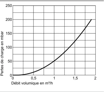
Courbes hydrauliques type AWO-AC 301.A Diagramme des pertes de charge
0
Débit volumique en m³/h
Pertes de charge en mbar
1,5 250 200 2 1 0,5 0 150 100 50
Courbes hydrauliques type AWCI-AC 301.A
Hauteur manométrique résiduelle du circulateur haute efficacité VI Para 25/1-7 intégré
Sans système chauffant électrique Avec système chauffant électrique (accessoire)
0
Débit volumique en m³/h
Hauteur manométrique résiduelle en mbar
500 400 1,5 1 0,5 0 300 200 100 2 600 800 700 0 Débit volumique en m³/h
Hauteur manométrique résiduelle en mbar
500 400 1,5 1 0,5 0 300 200 100 2 600 800 700
Diagramme de puissance du circulateur intégré
0 1 2 3 4 Débit en m³/h 0 40 60 Puissance en W
Vitocal 300-A (suite)
VITOCAL VIESMANN 13
5817 437 B/f
11.7– 33
5461716 5461716
Applicable à partir du 1 août 2014
Installation de chauffage Régulation Type
Variante de montage Equipement 3,0 - 9,03,0 - 6,6 GM 40
n
$76 0 0n 1 circuit de chauffage sans vanne
mélangeuse
n 1 ou 2 circuits de chauffage avec vanne
mélangeuse
Régulation de pompe à chaleur Vitotronic 200
Type WO1B, pour marche en fonction de la température extérieure
n Régulation de pompe à chaleur numérique. n Régulation ECS.
n Commande à menu déroulant. n Système de diagnostic intégré.
n Commande d'un système chauffant électrique.
n Commande d'une chaudière mazout/gaz supplémentaire. n Couplage en cascade de maximum 5 Vitocal (accessoires
néces-saires).
n Fonction de régulation du rafraîchissement "active cooling". n Chauffage de l'eau de piscine.
n Contrôle du coefficient de performance annuel/bilan énergétique
intégrés.
n Dialogue possible avec les Vitocom 100, 200 et 300.
Des extensions (voir Accessoires) sont nécessaires pour chaque circuit de chauffage avec vanne mélangeuse, la chaudière mazout/gaz supplé-mentaire, la fonction de régulation du rafraîchissement et le chauffage de l'eau de piscine.
Les câbles de liaison électriques reliant la régulation à la pompe à chaleur sont à mentionner sur la commande (voir Accessoires).
AWCI-AC 301.A09
Installation à l'intérieur Z00987813.820,– RéférenceFr.
n
► Caractéristiques techniques, voir page 11.7-36.
Vitocal 300-a/350-a
Pompes à chaleur air/eau Vitocal 300-A Plage de puissance nominale (kW) au point de fonctionnement A2/W35 ou A-7/W35
THIS DRAWING IS STRICTLY PRIVATE AND CONFIDENTIAL AND IS THE SOLE PROPERTY OF E.J. BOWMAN (BIRMINGHAM) LTD. IT IS SUBJECT TO BOTH COPYRIGHT AND DESIGN RIGHT
PROTECTION. ANY REPRODUCTION OF THIS DRAWING IN PART OR WHOLE SHALL BE MADE ONLY WITH THE WRITTEN CONSENT OF A DIRECTOR OF THE COMPANY.
DO NOT SCALE - IF IN DOUBT ASK!
Chester Street Birmingham B6 4AP England
Tel: +44(0) 121 359 5401 Fax: +44(0) 121 359 7495
email: info@ejbowman.co.uk www.ejbowman.co.uk
E.J.BOWMAN (BIRMINGHAM) LTD.
ALL DIMENSIONS ARE IN MILLIMETRES
DATE:
REDRAWN:
DATE:
CHECKED:
SCALE:
DRAWN:
REG. No. FM38224 BS EN ISO 9001:2008DRG No:
TITLE:
3-40 Exhaust Gas
J. SWAIN
3738-6
17/06/2012
1:1
Heat Exchanger
7
5
54
60 crs
140
10
962 crs
920 crs
1162 Overall
1" BSP
3
/4
"
B
S
P
1" BSP
Direction Of Water Flow
Direction Of Exhaust Gas Flow
Exhaust
Gas
Exhaust
Gas
Water
Flow
Water
Flow
915B
915
1
Plug -
" BSP
12
Brass
EX033-4058CI
4058
1
EX33 End Cover Eccentric
11
C.I.
3597
3597
1
CSK Plug -
" BSP
10
C.I.
4463
4463
1
Nameplate
9
S.S.
916
916
2
Plug -
" BSP
8
Brass
4028
4028
1
Safety Valve
7
Brass
4477
4477
2
Mounting foot
6
M.S.
HS08X35SS
-
16
Socket Screw - M8 x 35mm
5
S.S.
HN08SS
-
16
Hex Head Nut - M8
4
S.S.
3788
3788
2
Gasket
3
SP-AF/II
EX003-3758CI
3758
1
EX3 End Cover Concentric
2
C.I.
3778-6TD
3778-6
1
Tubestack 3-40
1
S.S.
Part No.
Drg No.
Qty
Description
Item
Material
Notes:
Maximum Working Water Pressure - 4 Bar
Maximum Working Water Temperature - 110 C
Maximum Working Exhaust Gas Pressure - 0.5 Bar
Maximum Working Exhaust Gas Temperature - 700 C
See Range Drawing No. 3738 For Revision History.
2
3
4
6
7
8
9
10
11
8
7
5
1
12
90
8
8
.9
ISS No
MODIFICATION
DATE
SIGN
2
Full Part Numbers Added To BoM, BSI Logo Updated
11/11/14
J. SWAIN
3/4" BSP
1
6
c
rs
5
Boss For Temp Probe For Engine
Shut Down Equipment (Not Supplied)
4 Mounting Holes 9mm
Exhaust Flanges 4 Holes Equi-Spaced
As Shown on 110mm PCD Drilled 14mm
QUOTATION
EJ Bowman (Birmingham) Limited
Chester Street
Telephone:+44 (0)121 359 5401
Birmingham B6 4AP
Facsimile:+44 (0)121 359 7495
England
E-Mail:info@ejbowman.co.uk
To R&D Carbon Ltd. From Jim Johnson
Email matthieu.arlettaz@rd-carbon.com Date 1 December 2014
Attention Matthieu Arlettaz Ref. JMJ/E0905
Your ref. Email Enquiry No. of pages 2
Dear Matthieu
We thank you for your enquiry of 28 November and have pleasure in submitting the following
quotation.
Part No.
Shell Side: 50% EG Solution Tube Side: Diesel Engine Exhaust
Flow rate Temp (°C) P Drop Flow rate Temp (°C) P Drop Heat
l/min In Out kPa kg/min In Out kPa kW
3-40-3738-6 23.8 75 89.6 1.5 2.8 570 180 2.1 20.3
Please find attached copy drawing of the above unit.
We hope you will find our prices to be competitive and look forward to receiving your
response with interest.
Kind regards
Jim Johnson
Sales Engineer
SUBJECT TO THE FOLLOWING TERMS AND CONDITIONS
Pressure Test - Pressure Test Certificate 5% cost of the heat exchanger or €10.00 whichever the greater.
Certification - Certificate of Guarantee €10.00 each.
Documentation - If commercial invoices are required to be certified by our local Chamber of Commerce, an additional cost of €35.00 will be incurred.
Terms of Sale - FCA Bowman Works (formerly Ex Works). Carriage Charges - Extra and for your account.
Despatch Time - 2 - 3 working weeks from receipt of payment.
Payment Terms - Prepayment required.
Validity - 30 days from date of quotation.
Christmas Holidays
These offices are closed from 13.00 hours, Wednesday, 24 December 2014 until 9.00 hours, Monday, 5 January 2015.
Quantity
Part Number
Description
Unit Price
C:\Users\ADMIN\Documents\01_HES\DIPLOME\08_Diplome\03 automation\database\recorder_1min.sql jeudi 9 juillet 2015 16:42
delimiter $$
CREATE TABLE `voltage_1min` (
`ID` mediumint(20) unsigned NOT NULL AUTO_INCREMENT,
`timestamp` datetime DEFAULT NULL,
`voltage_1_1` float DEFAULT NULL,
`voltage_1_2` float DEFAULT NULL,
`voltage_1_3` float DEFAULT NULL,
`voltage_2_1` float DEFAULT NULL,
`voltage_2_2` float DEFAULT NULL,
`voltage_2_3` float DEFAULT NULL,
`voltage_3_1` float DEFAULT NULL,
`voltage_3_2` float DEFAULT NULL,
`voltage_3_3` float DEFAULT NULL,
`voltage_4_1` float DEFAULT NULL,
`voltage_4_2` float DEFAULT NULL,
`voltage_4_3` float DEFAULT NULL,
`voltage_5_1` float DEFAULT NULL,
`voltage_5_2` float DEFAULT NULL,
`voltage_5_3` float DEFAULT NULL,
`voltage_6_1` float DEFAULT NULL,
`voltage_6_2` float DEFAULT NULL,
`voltage_6_3` float DEFAULT NULL,
`voltage_7_1` float DEFAULT NULL,
`voltage_7_2` float DEFAULT NULL,
`voltage_7_3` float DEFAULT NULL,
`voltage_8_1` float DEFAULT NULL,
`voltage_8_2` float DEFAULT NULL,
`voltage_8_3` float DEFAULT NULL,
PRIMARY KEY (`ID`),
UNIQUE KEY `ID_UNIQUE` (`ID`)
) ENGINE=InnoDB DEFAULT CHARSET=latin1$$
CREATE TABLE `current_1min` (
`ID` mediumint(20) unsigned NOT NULL AUTO_INCREMENT,
`timestamp` datetime DEFAULT NULL,
`current_1_1` float DEFAULT NULL,
`current_1_2` float DEFAULT NULL,
`current_1_3` float DEFAULT NULL,
`current_2_1` float DEFAULT NULL,
`current_2_2` float DEFAULT NULL,
`current_2_3` float DEFAULT NULL,
`current_3_1` float DEFAULT NULL,
`current_3_2` float DEFAULT NULL,
`current_3_3` float DEFAULT NULL,
`current_4_1` float DEFAULT NULL,
`current_4_2` float DEFAULT NULL,
`current_4_3` float DEFAULT NULL,
`current_5_1` float DEFAULT NULL,
`current_5_2` float DEFAULT NULL,
`current_5_3` float DEFAULT NULL,
`current_6_1` float DEFAULT NULL,
`current_6_2` float DEFAULT NULL,
`current_6_3` float DEFAULT NULL,
`current_7_1` float DEFAULT NULL,
`current_7_2` float DEFAULT NULL,
-1-C:\Users\ADMIN\Documents\01_HES\DIPLOME\08_Diplome\03 automation\database\recorder_1min.sql jeudi 9 juillet 2015 16:42
`current_7_3` float DEFAULT NULL,
`current_8_1` float DEFAULT NULL,
`current_8_2` float DEFAULT NULL,
`current_8_3` float DEFAULT NULL,
PRIMARY KEY (`ID`),
UNIQUE KEY `ID_UNIQUE` (`ID`)
) ENGINE=InnoDB DEFAULT CHARSET=latin1$$
CREATE TABLE `power_1min` (
`ID` mediumint(20) unsigned NOT NULL AUTO_INCREMENT,
`timestamp` datetime DEFAULT NULL,
`power_1_1` float DEFAULT NULL,
`power_1_2` float DEFAULT NULL,
`power_1_3` float DEFAULT NULL,
`power_2_1` float DEFAULT NULL,
`power_2_2` float DEFAULT NULL,
`power_2_3` float DEFAULT NULL,
`power_3_1` float DEFAULT NULL,
`power_3_2` float DEFAULT NULL,
`power_3_3` float DEFAULT NULL,
`power_4_1` float DEFAULT NULL,
`power_4_2` float DEFAULT NULL,
`power_4_3` float DEFAULT NULL,
`power_5_1` float DEFAULT NULL,
`power_5_2` float DEFAULT NULL,
`power_5_3` float DEFAULT NULL,
`power_6_1` float DEFAULT NULL,
`power_6_2` float DEFAULT NULL,
`power_6_3` float DEFAULT NULL,
`power_7_1` float DEFAULT NULL,
`power_7_2` float DEFAULT NULL,
`power_7_3` float DEFAULT NULL,
`power_8_1` float DEFAULT NULL,
`power_8_2` float DEFAULT NULL,
`power_8_3` float DEFAULT NULL,
PRIMARY KEY (`ID`),
UNIQUE KEY `ID_UNIQUE` (`ID`)
) ENGINE=InnoDB DEFAULT CHARSET=latin1$$
CREATE TABLE `cosphi_1min` (
`ID` mediumint(20) unsigned NOT NULL AUTO_INCREMENT,
`timestamp` datetime DEFAULT NULL,
`cosphi_1_1` float DEFAULT NULL,
`cosphi_1_2` float DEFAULT NULL,
`cosphi_1_3` float DEFAULT NULL,
`cosphi_2_1` float DEFAULT NULL,
`cosphi_2_2` float DEFAULT NULL,
`cosphi_2_3` float DEFAULT NULL,
`cosphi_3_1` float DEFAULT NULL,
`cosphi_3_2` float DEFAULT NULL,
`cosphi_3_3` float DEFAULT NULL,
`cosphi_4_1` float DEFAULT NULL,
`cosphi_4_2` float DEFAULT NULL,
`cosphi_4_3` float DEFAULT NULL,
`cosphi_5_1` float DEFAULT NULL,
`cosphi_5_2` float DEFAULT NULL,
-2-C:\Users\ADMIN\Documents\01_HES\DIPLOME\08_Diplome\03 automation\database\recorder_1min.sql jeudi 9 juillet 2015 16:42
`cosphi_5_3` float DEFAULT NULL,
`cosphi_6_1` float DEFAULT NULL,
`cosphi_6_2` float DEFAULT NULL,
`cosphi_6_3` float DEFAULT NULL,
`cosphi_7_1` float DEFAULT NULL,
`cosphi_7_2` float DEFAULT NULL,
`cosphi_7_3` float DEFAULT NULL,
`cosphi_8_1` float DEFAULT NULL,
`cosphi_8_2` float DEFAULT NULL,
`cosphi_8_3` float DEFAULT NULL,
PRIMARY KEY (`ID`),
UNIQUE KEY `ID_UNIQUE` (`ID`)
) ENGINE=InnoDB DEFAULT CHARSET=latin1$$
CREATE TABLE `frequency_1min` (
`ID` mediumint(20) unsigned NOT NULL AUTO_INCREMENT,
`timestamp` datetime DEFAULT NULL,
`frequency_1` float DEFAULT NULL,
`frequency_2` float DEFAULT NULL,
`frequency_3` float DEFAULT NULL,
`frequency_4` float DEFAULT NULL,
`frequency_5` float DEFAULT NULL,
`frequency_6` float DEFAULT NULL,
`frequency_7` float DEFAULT NULL,
`frequency_8` float DEFAULT NULL,
PRIMARY KEY (`ID`),
UNIQUE KEY `ID_UNIQUE` (`ID`)
) ENGINE=InnoDB DEFAULT CHARSET=latin1$$
CREATE TABLE `temperature_1min` (
`ID` mediumint(20) unsigned NOT NULL AUTO_INCREMENT,
`timestamp` datetime DEFAULT NULL,
`temperature_1` float DEFAULT NULL,
`temperature_2` float DEFAULT NULL,
`temperature_3` float DEFAULT NULL,
`temperature_4` float DEFAULT NULL,
`temperature_5` float DEFAULT NULL,
`temperature_6` float DEFAULT NULL,
`temperature_7` float DEFAULT NULL,
`temperature_8` float DEFAULT NULL,
`temperature_9` float DEFAULT NULL,
`temperature_10` float DEFAULT NULL,
`temperature_11` float DEFAULT NULL,
`temperature_12` float DEFAULT NULL,
`temperature_13` float DEFAULT NULL,
`temperature_14` float DEFAULT NULL,
`temperature_15` float DEFAULT NULL,
`temperature_16` float DEFAULT NULL,
`temperature_17` float DEFAULT NULL,
`temperature_18` float DEFAULT NULL,
`temperature_19` float DEFAULT NULL,
`temperature_20` float DEFAULT NULL,
PRIMARY KEY (`ID`),
UNIQUE KEY `ID_UNIQUE` (`ID`)
) ENGINE=InnoDB DEFAULT CHARSET=latin1$$
CREATE TABLE `level_1min` (
-3-C:\Users\ADMIN\Documents\01_HES\DIPLOME\08_Diplome\03 automation\database\recorder_1min.sql jeudi 9 juillet 2015 16:42
`ID` mediumint(20) unsigned NOT NULL AUTO_INCREMENT,
`timestamp` datetime DEFAULT NULL,
`niveau_1` float DEFAULT NULL,
`niveau_2` float DEFAULT NULL,
`niveau_3` float DEFAULT NULL,
`niveau_4` float DEFAULT NULL,
`niveau_5` float DEFAULT NULL,
`niveau_6` float DEFAULT NULL,
`niveau_7` float DEFAULT NULL,
`niveau_8` float DEFAULT NULL,
`niveau_9` float DEFAULT NULL,
`niveau_10` float DEFAULT NULL,
PRIMARY KEY (`ID`),
UNIQUE KEY `ID_UNIQUE` (`ID`)
) ENGINE=InnoDB DEFAULT CHARSET=latin1$$
CREATE TABLE `pressure_1min` (
`ID` mediumint(20) unsigned NOT NULL AUTO_INCREMENT,
`timestamp` datetime DEFAULT NULL,
`pression_1` float DEFAULT NULL,
`pression_2` float DEFAULT NULL,
`pression_3` float DEFAULT NULL,
`pression_4` float DEFAULT NULL,
`pression_5` float DEFAULT NULL,
`pression_6` float DEFAULT NULL,
`pression_7` float DEFAULT NULL,
`pression_8` float DEFAULT NULL,
`pression_9` float DEFAULT NULL,
`pression_10` float DEFAULT NULL,
PRIMARY KEY (`ID`),
UNIQUE KEY `ID_UNIQUE` (`ID`)
) ENGINE=InnoDB DEFAULT CHARSET=latin1$$
CREATE TABLE `analog_1min` (
`ID` mediumint(20) unsigned NOT NULL AUTO_INCREMENT,
`timestamp` datetime DEFAULT NULL,
`analog_1` float DEFAULT NULL,
`analog_2` float DEFAULT NULL,
`analog_3` float DEFAULT NULL,
`analog_4` float DEFAULT NULL,
`analog_5` float DEFAULT NULL,
`analog_6` float DEFAULT NULL,
`analog_7` float DEFAULT NULL,
`analog_8` float DEFAULT NULL,
`analog_9` float DEFAULT NULL,
`analog_10` float DEFAULT NULL,
`analog_11` float DEFAULT NULL,
`analog_12` float DEFAULT NULL,
`analog_13` float DEFAULT NULL,
`analog_14` float DEFAULT NULL,
`analog_15` float DEFAULT NULL,
`analog_16` float DEFAULT NULL,
`analog_17` float DEFAULT NULL,
`analog_18` float DEFAULT NULL,
`analog_19` float DEFAULT NULL,
`analog_20` float DEFAULT NULL,
PRIMARY KEY (`ID`),
-4-C:\Users\ADMIN\Documents\01_HES\DIPLOME\08_Diplome\03 automation\database\recorder_1min.sql jeudi 9 juillet 2015 16:42
UNIQUE KEY `ID_UNIQUE` (`ID`)
) ENGINE=InnoDB DEFAULT CHARSET=latin1$$
CREATE TABLE `contact_1min` (
`ID` mediumint(20) unsigned NOT NULL AUTO_INCREMENT,
`timestamp` datetime DEFAULT NULL,
`contact_1` tinyint DEFAULT NULL,
`contact_2` tinyint DEFAULT NULL,
`contact_3` tinyint DEFAULT NULL,
`contact_4` tinyint DEFAULT NULL,
`contact_5` tinyint DEFAULT NULL,
`contact_6` tinyint DEFAULT NULL,
`contact_7` tinyint DEFAULT NULL,
`contact_8` tinyint DEFAULT NULL,
`contact_9` tinyint DEFAULT NULL,
`contact_10` tinyint DEFAULT NULL,
`contact_11` tinyint DEFAULT NULL,
`contact_12` tinyint DEFAULT NULL,
`contact_13` tinyint DEFAULT NULL,
`contact_14` tinyint DEFAULT NULL,
`contact_15` tinyint DEFAULT NULL,
`contact_16` tinyint DEFAULT NULL,
`contact_17` tinyint DEFAULT NULL,
`contact_18` tinyint DEFAULT NULL,
`contact_19` tinyint DEFAULT NULL,
`contact_20` tinyint DEFAULT NULL,
`contact_21` tinyint DEFAULT NULL,
`contact_22` tinyint DEFAULT NULL,
`contact_23` tinyint DEFAULT NULL,
`contact_24` tinyint DEFAULT NULL,
`contact_25` tinyint DEFAULT NULL,
`contact_26` tinyint DEFAULT NULL,
`contact_27` tinyint DEFAULT NULL,
`contact_28` tinyint DEFAULT NULL,
`contact_29` tinyint DEFAULT NULL,
`contact_30` tinyint DEFAULT NULL,
PRIMARY KEY (`ID`),
UNIQUE KEY `ID_UNIQUE` (`ID`)
) ENGINE=InnoDB DEFAULT CHARSET=latin1$$
-5-C:\Users\ADMIN\Documents\01_HES\DIPLOME\08_Diplome\03 automation\database\recorder_procedure.sql jeudi 9 juillet 2015 16:44
delimiter $$
CREATE DEFINER=`root`@`%` PROCEDURE `analog_procedure`(IN timecode text,IN arg1 float,IN arg2
float,IN arg3 float,IN arg4 float,IN arg5 float,IN arg6 float,IN arg7 float,IN arg8 float,IN
arg9 float,IN arg10 float,IN arg11 float,IN arg12 float,IN arg13 float,IN arg14 float,IN
arg15 float,IN arg16 float,IN arg17 float,IN arg18 float,IN arg19 float,IN arg20 float,IN
arg21 float,IN arg22 float,IN arg23 float,IN arg24 float,IN arg25 float ,IN arg26 float,IN
arg27 float,IN arg28 float,IN arg29 float,IN arg30 float)
BEGIN
INSERT INTO weisshorn_recorder.analog_1min VALUES (NULL,timecode,arg1,arg2,arg3,arg4,arg5,
arg6,arg7,arg8,arg9,arg10,arg11,arg12,arg13,arg14,arg15,arg16,arg17,arg18,arg19,arg20);
END$$
delimiter $$
CREATE DEFINER=`root`@`%` PROCEDURE `contact_procedure`(IN timecode text,IN arg1 float,IN
arg2 float,IN arg3 float,IN arg4 float,IN arg5 float,IN arg6 float,IN arg7 float,IN arg8
float,IN arg9 float,IN arg10 float,IN arg11 float,IN arg12 float,IN arg13 float,IN arg14
float,IN arg15 float,IN arg16 float,IN arg17 float,IN arg18 float,IN arg19 float,IN arg20
float,IN arg21 float,IN arg22 float,IN arg23 float,IN arg24 float,IN arg25 float ,IN arg26
float,IN arg27 float,IN arg28 float,IN arg29 float,IN arg30 float)
BEGIN
INSERT INTO weisshorn_recorder.contact_1min VALUES (NULL,timecode,arg1,arg2,arg3,arg4,arg5,
arg6,arg7,arg8,arg9,arg10,arg11,arg12,arg13,arg14,arg15,arg16,arg17,arg18,arg19,arg20,arg21,
arg22,arg23,arg24,arg25,arg26,arg27,arg28,arg29,arg30);
END$$
delimiter $$
CREATE DEFINER=`root`@`%` PROCEDURE `cosphi_procedure`(IN timecode text,IN arg1 float,IN arg2
float,IN arg3 float,IN arg4 float,IN arg5 float,IN arg6 float,IN arg7 float,IN arg8 float,IN
arg9 float,IN arg10 float,IN arg11 float,IN arg12 float,IN arg13 float,IN arg14 float,IN
arg15 float,IN arg16 float,IN arg17 float,IN arg18 float,IN arg19 float,IN arg20 float,IN
arg21 float,IN arg22 float,IN arg23 float,IN arg24 float,IN arg25 float ,IN arg26 float,IN
arg27 float,IN arg28 float,IN arg29 float,IN arg30 float)
BEGIN
INSERT INTO weisshorn_recorder.cosphi_1min VALUES (NULL,timecode,arg1,arg2,arg3,arg4,arg5,
arg6,arg7,arg8,arg9,arg10,arg11,arg12,arg13,arg14,arg15,arg16,arg17,arg18,arg19,arg20,arg21,
arg22,arg23,arg24);
END$$
delimiter $$
CREATE DEFINER=`root`@`%` PROCEDURE `current_procedure`(IN timecode text,IN arg1 float,IN
arg2 float,IN arg3 float,IN arg4 float,IN arg5 float,IN arg6 float,IN arg7 float,IN arg8
float,IN arg9 float,IN arg10 float,IN arg11 float,IN arg12 float,IN arg13 float,IN arg14
float,IN arg15 float,IN arg16 float,IN arg17 float,IN arg18 float,IN arg19 float,IN arg20
float,IN arg21 float,IN arg22 float,IN arg23 float,IN arg24 float,IN arg25 float ,IN arg26
float,IN arg27 float,IN arg28 float,IN arg29 float,IN arg30 float)
BEGIN
INSERT INTO weisshorn_recorder.current_1min VALUES (NULL,timecode,arg1,arg2,arg3,arg4,arg5,
arg6,arg7,arg8,arg9,arg10,arg11,arg12,arg13,arg14,arg15,arg16,arg17,arg18,arg19,arg20,arg21,
arg22,arg23,arg24);
END$$