Investigation into the potential of low-oxygen and dry/cold storage for freshly excavated iron artifacts
186
0
0
Texte intégral
(2) Illustrations title page: Dry storage of archaeological metal at English Heritage, Centre of Archaeology, Fort Cumberland, Portsmouth, United Kingdom; Diagram of vertically growing, voluminous akaganéite (β-FeOOH). (SELWYN L. S., SIROIS P.J., ARGYROPOULOS V., 1999, p226)..
(3) Acknowledgements Many thanks go to: My mentor: François Schweizer, Morges, Switzerland, for his helpful assistance and support over the year of this work and for important inputs as well as for his patience and structured comments. My supervisor: David Thickett, Senior Conservation Scientist, English Heritage, London, United Kingdom, for providing access to all necessary infrastructure as well as for advice, information and guidance over the period of this project. As well as: Dr. Marianne Odlyha, School of Biological and Chemical Sciences, Chair, Examinations Board, Birkbeck College, London, United Kingdom, for welcoming me at the laboratory, providing access to Fourier-transform infrared spectroscopy (FT-IR), putting me in contact with helpful people and inputs from a very scientific point of view. Chris Collins, Head of Conservation, Department of Palaeontology, The Natural History Museum, London, United Kingdom, for providing access to the oxygen monitoring system in use at the NHM as well as for the enthusiasm shown regarding my project. Dr. James Parker, Conservation Scientist, British Museum, London, United Kingdom, for access to oxygen monitoring and heat-sealing equipment as well as for his advice on questions with regard to the analytical techniques used. To the following institutions: English Heritage, Birkbeck College, The Natural History Museum and British Museum, United Kingdom, for equipment, materials and welcoming me. Special thanks for their help and share of experiences to: Vanessa Fell, Archaeological Conservator, for welcoming me at Fort Cumberland, English Heritage, Portsmouth, providing access to X-ray diffraction (XRD) and sharing experience, as well as for the warm welcome at her place; Naomi Luxford, Conservation Scientist, for help with software and dataloggers as well as for advice on the structure of this work, and for the experience shared; Adam Webster, Senior Conservator (Fine Art), English Heritage, for his patience with the test set up at Ranger’s House Painting Studio and for providing space for the present test series, and Alex Gent, Painting Conservator, for checking test setup conditions at Ranger’s House; Amber Xavier-Rowe, Head of Collections Management, Roger Wilkes, Technician, and Sarah Paynter, Archaeological Scientist, all from English Heritage for welcoming and helping me;.
(4) Dr. Charis Theodorakopoulos at Birkbeck College for encouragement, support and helpful inputs; Rebecca Dean for providing access to the library at the British Museum. Thanks as well to Libby Sheldon, Department of History of Art, University College London, for access to polishing equipment; Dr. Tracey Chaplin, for providing access to Raman spectroscopy and help with interpretation of data; Jie Gao, student at University College London, Institute of Archaeology for help with the sample preparation and Lu Allington, Conservator, Natural History Museum, London, for help with tests on the oxygen absorbers; Dr. Christian Degrigny, for advice and help with open questions; Christoph Waller, Long Life for Art, Gottenheim, Germany, for supply of materials and advice concerning oxygen-free storage; Markus Detmer, Conservator, Archaeological Office of the Canton of Bern, (Archäologischer Dienst des Kantons Bern), Switzerland, for providing image material on archaeological iron; Dr. Marcel Mayer, Municipal Archivist of the Municipality of St.Gallen (Stadtarchivar, Stadtarchiv der politischen Gemeinde St.Gallen), Switzerland, for providing access to scanning facilities. To the following Swiss institutions for supplying archaeological material and documentation: Archaeological Office of the Canton of Fribourg (Service Archéologique de l'Etat de Fribourg, Fribourg: Cyril Benoît and Carmen Buchiller); Archaeological Office of the Canton of Aargau (Archäologischer Dienst des Kantons Aargau, Brugg: Judith Fuchs); Roman town of Augusta Raurica (Römerstadt Augusta Raurica, Augst: Maria-Luisa Fernández); Roman site and museum of Avenches (Site et Musée Romains d’Avenches: Verena Fischbacher); Archaeological Office of the Canton of Bern (Archäologischer Dienst des Kantons Bern, Bern: Christoph Rogalla von Bieberstein). My school and my teachers in Switzerland: Valentin Boissonnas, School of the University of Applied Sciences Western Switzerland – HES-SO (Haute école d’arts appliqués Arc), Conservation, La Chaux-de-Fonds, for encouragement and support during this year; Nathalie Ducatel, Doyenne, School of the University of Applied Sciences Western Switzerland – HES-SO (Haute école d’arts appliqués Arc), Conservation, La Chaux-deFonds. As well as to Tobias Schenkel, Christian Binet, Esther Jacquemettaz and Julita Beck for support during the training. Thanks to the Bernische Denkmalpflege-Stiftung for financial support. To my family for their important emotional as well as financial support: Dorothee Guggenheimer for reading, important support and advice. Anna Ruchti-Guggenheimer, Emanuel Guggenheimer, Regula Guggenheimer and Michael Guggenheimer, Ellen Guggenheimer..
(5) And special thanks to: Käthi Löpfe as well as Jean-Michel Moreillon. For concentrated reading thanks go to Rachel Mazzucco and Martin Striegel. I owe thanks to the following people for their very individual support during the year of this project: Patrizia and Don Ross with Gino, Jeremy and Ema Gaywood with Mia, Luisa Beeli and Nina Langosch, Mirjam Balsiger, Jana Egger, Chloé Maquelin, Corine Estoppey, Carmen Pfister, Céline Dürr and David Loher, Reto Kromer, Daphne Stumpp, Sabina Granov, Anna-Lena Adamsson, Clotilde Proust..
(6) Abstract Once archaeological iron artifacts are excavated their protective environment is lost. On exposure to the air the objects can dry out and the earthy as well as the corrosion layers become permeable due to the formation of cracks and fissures. Moisture from the air and oxygen get access to the objects. If chlorides are present in the corrosion layers and metallic iron remains in the artifact, active corrosion can be a consequence if the objects are left in an uncontrolled environment. Akaganéite (β-FeOOH) is the visible sign of active corrosion. It is a voluminous orange-brown corrosion product that forms after excavation on iron artifacts in the presence of moisture and oxygen. Chlorides need to be present in the object, as they are the controlling factor of the reaction that leads to akaganéite (β-FeOOH). Adequate methods of storing the iron finds can prevent these destructive corrosion reactions. In this work, two different storage methods are examined with regard to their efficiency of preventing akaganéite (β-FeOOH). Synthetic and archaeological samples are packed into these storage environments. Synthetic samples submitted to the test conditions are made up of a powder mixture of iron and iron chloride hydrate in equal amounts. Archaeological samples (Roman nails from two Swiss excavation sites) are packed alongside the synthetic samples. Dry or dry and cold storage are compared to results of oxygen-free storage. For dry and cold storage, samples are packed in resealable polyethylene (PE) bags that are placed into polypropylene (PP) boxes. Silica gel is used as a desiccant for dry microclimates. For the oxygen-free storage, two oxygen absorbers from the RP-System. TM. produced by Mitsubishi Gas Chemical Company are tested. These. are the RP-A absorber that creates an oxygen-free dry climate and the RP-K absorber that lowers the oxygen level, but does not affect the relative humidity (RH). Samples in anoxic environments are TM. packed into bags made of a high barrier film (ESCAL ). Changes over a period of five-and-a-half months in the samples are analysed using Fourier-transform infrared spectroscopy (FT-IR), X-ray diffraction (XRD) and optical microscopy. Results of the present work show that dry packing of samples using resealable PE bags provided with holes placed into PP boxes as well as dry oxygen-free storage in fully heat-sealed barrier film bags show the most promising results. Temporary dry oxygen-free storage using barrier film bags closed with a clip could be an option for on-site packaging of objects until arrival in the laboratory, where dry storage could be an easy way of dealing with objects that have to be further examined or put on display. Dry oxygen-free storage is a realistic option for the large amount of iron objects that will never go on display, but be kept in storage. Economic aspects of the tested storage methods are also examined. Anoxic storage proves to be expensive in the phase of setting up the packaging.. Résumé Après une fouille, le taux d' humidité et d'oxygène de l'air affecte tout objet archéologique en fer. Les couches de terre et de corrosion, par l’action de l’air, dessèchent et des craquelures peuvent alors s’y créer. Ainsi l’oxygène et l’humidité ont accès à ces couches de corrosion et à l’intérieur de l’objet. La.
(7) corrosion est activée par les conditions atmosphériques et est accentuée en présence de chlorures au sein de l'objet. L'un des principaux produits de corrosion visible à l'oeil nu est l'akaganéite (β-FeOOH) de couleur brun-orangé. L’akaganéite (β-FeOOH) occupe beaucoup de volume et peut faire éclater des couches de corrosion qui lui sont superposées. Cette étude montre l'importance d'un stockage adéquat afin de ralentir voir de stopper les réactions des agents corrosifs. Deux méthodes de stockage sont analysées afin de déterminer leur efficacité à empêcher le processus de formation d'akaganéite (β-FeOOH). Les échantillons stockés sont de deux types: - les échantillons synthétiques (fer et chlorure de fer hydraté en poudre) - les échantillons archéologiques (clous romains provenant de deux sites suisses). Ils sont soumis conjointement (en parallèle) à diverses conditions de stockage. Premièrement le stockage au sec et sec/froid où on a placé les échantillons dans des sachets en polyéthylène (PE) dans des container en polypropylène (PP). On utilise le gel de silice pour obtenir un climat sec. Deuxièmement l’anoxie sèche où on utilise le RP-System. TM. de Mitsubishi Gas Chemical Company. avec ses deux absorbeurs d’oxygène RP-A et RP-K. Le premier crée un climat sec et sans oxygène, le deuxième baisse l’oxygène, mais n’influence pas l’humidité relative (HR). Dans ce cas on utilise des TM. sachets en film plastique à indice de perméabilité très bas (ESCAL ) pour l’emballage. Les échantillons sont examinés et comparés sur une période de plus de 5 mois. Ils sont analysés par spectrométrie infrarouge transformée de Fourier (FT-IR), diffraction à rayons X (XRD) et microscopie optique. Les résultats obtenus démontrent l'intérêt à considérer un aspect de stockage à long et court terme. Deux modes de stockage à long terme sont retenus. Le stockage sec, avec sachets PE troués dans des containers PP pour des objets d’exposition et ceux qui attendent des analyses et doivent être dessinés. L’anoxie sèche dans des sachets entièrement soudés pour les objets qui rentrent en réserve pour une durée indéterminée. Le stockage à anoxie temporaire utilisant des sachets de film peu perméable à fermeture clip est retenu pour le court terme pour les travaux in-situ, avant l'arrivée des objets au laboratoire. Pour conclure, l'étude permet de mettre en évidence l'aspect économique des modes de stockage à long et court termes. En effet, la mise en œuvre de l’anoxie coûte cher dans la phase initiale.. Zusammenfassung Nach einer Ausgrabung können Feuchtigkeit und Sauerstoff uneingeschränkten Zugang zum ungeschützten Eisenobjekt haben. Sind Chloride und ein Metallkern im Objekt vorhanden, so kann aktive Korrosion eine Folge sein von unkontrollierter Lagerung der Frischfunde. Das sichtbare Anzeichen von aktiver Korrosion auf Eisenobjekten ist Akaganeit (β-FeOOH). Dies ist ein orange-braunes voluminöses Korrosionsprodukt, das nach der Ausgrabung unter Einfluss von Feuchtigkeit und Sauerstoff entsteht. Bedingung für diese Korrosion ist das Vorhandensein von Chloriden, da sie den massgebenden Faktor darstellen, der zur Akaganeit (β-FeOOH)- Bildung führt. Angemessene Lagerungsmethoden können diese zerstörerischen Reaktionen verhindern..
(8) Die vorliegende Arbeit untersucht zwei Lagerungsmethoden und deren Fähigkeit, Akaganeit (βFeOOH)-Bildung zu verhindern. Dazu werden synthetische und archäologische Proben während fünfeinhalb Monaten den Lagerungsbedingungen unterworfen. Die synthetischen Proben bestehen aus einer Mischung gleicher Mengen Eisen und Eisenchlorid. Weiter werden archäologische Proben (römische Nägel von zwei Schweizer Ausgrabungen) ebenfalls mitverpackt. Untersucht. werden die. Eignung von Trockenlagerung und kalter. Trockenlagerung sowie. sauerstofffreier Lagerung zur Verhinderung von Akaganeit (β-FeOOH)-Bildung. Bei den Formen der Trockenlagerung werden die Proben in wiederverschliessbare Beutel aus Polyethylen (PE) verpackt und diese werden in Polypropylen (PP) Boxen gelegt. Als Trockenmittel wird Silica Gel verwendet. Bei der sauerstofffreien Lagerung werden zwei Sauerstoffabsorber des RP-System. TM. der Firma Mitsubishi. Gas Chemical Company verglichen. Der erste Absorber, RP-A, ergibt ein trockenes sauerstofffreies Klima. RP-K, der zweite Absorber, führt zur Anoxie ohne die relative Feuchte zu beeinflussen. In TM. dieser Untersuchung werden Beutel aus der Sperrschichtfolie ESCAL. verwendet.. Veränderungen im Probenmaterial werden mit Hilfe von Fourier-Transform-Infrarotspektroskopie (FTIR), Röntgendiffraktion (XRD) und optischer Mikroskopie untersucht. Die Untersuchung zeigt, dass Trockenlagerung in gelochten PE-Wiederverschlussbeuteln in PPBoxen sowie trockene, sauerstofffreie Lagerung viel versprechende Resultate ergeben. Temporäre trockene Anoxie, in der ein Sperrschichtfolienbeutel mit Hilfe eines Clips verschlossen wird, könnte eine effiziente Verpackung auf der Ausgrabung darstellen. Kommen die Objekte dann im Labor an, kann ein Wechsel zu Trockenlagerung für die Objekte vorgesehen werden, welche untersucht, gezeichnet oder ausgestellt werden. Trockene Anoxie in ganz zugeschweissten Beuteln ist eine Langzeitoption für all jene Objekte, die nie ausgestellt werden und für lange Zeit ins Depot zurückkehren. Zusätzlich werden die finanziellen Konsequenzen der erwähnten Lageungsmethoden mit in Betracht gezogen, wobei sich die sauerstoffreie Lagerung in der Anfangsphase als sehr kostenintensiv herausstellt.. Abbreviations General ac/d α-FeOOH β-FeOOH °C 2 cc/m /day cm CO2 EH Fe FeCl2 FeCl3 FeCl2·4H2O FeCl2·2H2O FeCl3·6H2O 2FeCl3·7H2O Fe2O3. Air changes per day Iron oxyhydroxide goethite Iron oxyhydroxide akaganéite Degree Celsius Cubic centimetres / square metre / day Centimetres Carbon dioxide English Heritage, United Kingdom Iron Iron(II) chloride Iron(III) chloride Iron chloride tetrahydrate Iron chloride dihydrate Iron chloride hexahydrate / iron(III) chloride 6-water Iron chloride heptahydrate / iron(III) chloride 7-water Iron oxide hematite.
(9) Fe3O4 FeOCl FeS2 g 2 g.H2O/m /day 2 g/m /day + H ICDD l LLDPE mg ml mm NaOH NHM O2 OPP PE PET PP ppm PVAC PVAL RH RP-A RP-K RP-System. TM. Iron oxide magnetite Iron oxide chloride Marcasite and pyrite (polymorphs of FeS2) Grams Grams water / square metre / day Grams / square metre / day Hydrogen ion International Centre for Diffraction Data Litres Linear low-density polyethylene Milligrams Millilitres Millimetres Sodium hydroxide Natural History Museum, London, United Kingdom Oxygen Orientated polypropylene Polyethylene Polyethylene terephthalate Polypropylene Parts per million Poly(vinyl acetate) Poly(vinyl alcohol) Relative Humidity TM Oxygen absorber RP-A (part of the RP-System from Mitsubishi Gas Chemical Company): for dry oxygen-free enclosures TM Oxygen absorber RP-K (part of the RP-System from Mitsubishi Gas Chemical Company): for oxygen-free enclosures Oxygen absorbing Revolutionary Preservation System (from Mitsubishi Gas Chemical Company). Techniques FT-IR SEM XRD. Fourier-transform infrared spectroscopy Scanning electron microscopy X-ray diffraction.
(10) Contents 1 INTRODUCTION. 1. 1.1 General introduction to the topic. 1. 1.2 Review. 1. 1.3 Choice of materials submitted for testing. 3. 1.4 Research project aims and objectives. 3. 2 CORROSION OF ARCHAEOLOGICAL IRON. 5. 2.1 Corrosion phenomenon. 5. 2.1.1 Corrosion during burial. 5. 2.1.2 Post-excavation corrosion. 10. 2.1.3 Observed corrosion products on iron from soil burial site. 16. 2.1.4 Some general reflections on evidence preserved in corrosion products and attitudes of conservators influencing further treatment success 2.2 Akaganéite (β-FeOOH). 17 18. 2.2.1 Occurrence. 18. 2.2.2 Structure. 19. 2.2.3 Formation. 21. 2.2.3.1 Conditions of formation. 21. 2.2.3.2 Process of formation (imitation of the corrosion reactions in freshly excavated iron) 2.2.4 Composition 2.2.4.1 Chlorine content 2.3 Akaganéite (β-FeOOH) in the daily life of conservators. 21 22 22 23. 3 DEALING WITH THE EXCAVATED IRON OBJECTS: TREATMENT AND STORAGE METHODS 3.1 Stabilisation treatment. 28 28. 3.1.1 Washing with water and early protective layers. 28. 3.1.2 Early approaches in electrolysis. 29. 3.1.3 Impregnation. 29. 3.1.4 Cleaning with chemicals. 30. 3.1.5 Methods based on reduction and heat. 30. 3.1.6 Chloride extraction by means of aqueous solutions. 31. 3.2 Four different ways of storing archaeological iron artifacts. 32. 3.2.1 Oxygen-free storage with oxygen absorbers. 32. 3.2.2 Inert gases. 36. 3.2.3 Storage at low relative humidity. 38. 3.2.4 Storage in the cold. 41. 3.3 Oxygen absorbers 3.3.1 General introduction. 42 42.
(11) 3.3.2 Product descriptions. 43. 3.3.3 Barrier films used with oxygen absorbers. 46 TM. 3.3.4 The production of an enclosure made of ESCAL. barrier film. 3.3.5 Monitoring the anoxic climate. 48 49. 4 RESEARCH PROJECT. 53. 4.1 Aims. 53. 4.2 Criteria taken into account for the tested storage systems. 54. 4.3 Criteria for the synthetic and archaeological samples. 55. 4.4 Test setup. 56. 4.4.1 Cold/dry storage of samples in polyethylene (PE) bags placed in polypropylene (PP) boxes. 56. 4.4.2 Oxygen-free storage of samples using the RP-System. TM. 4.5 Analytical techniques. 59 62. 4.5.1 Fourier-transform infrared spectroscopy (FT-IR) analysis. 63. 4.5.2 X-ray diffraction (XRD) using a powder diffractometer. 67. 4.5.3 Microscopy. 69. 4.5.4 Oxygen monitoring. 69. 5 RESULTS. 71. 5.1 Problem 1: Dry and cold storage. 71. 5.1.1 General observations. 71. 5.1.1.1 Powder samples. 71. 5.1.1.2 Archaeological samples. 72. 5.1.2 Observations under the microscope. 73. 5.1.2.1 Powder samples. 73. 5.1.2.2 Archaeological samples. 73. 5.1.3 Analytical results for the synthetic powder samples. 74. 5.1.3.1 Absolute amount of akaganéite (β-FeOOH) in the samples after fiveand-a-half months. 74. 5.1.3.2 Comparison of all sample groups: evolution of the relative amount of akaganéite (β-FeOOH). 75. 5.1.3.3 Detection of akaganéite (β-FeOOH): differences observed using Fourier-transform infrared spectroscopy (FT-IR) and X-ray diffraction (XRD). 76. 5.1.3.4 Differences in the height of the Fourier-transform infrared spectroscopy (FT-IR) absorption band at 848cm. -1. 5.2 Problem 2: Oxygen-free storage of samples 5.2.1 General observations. 78 79 79. 5.2.1.1 Powder samples. 79. 5.2.1.2 Archaeological samples. 80. 5.2.2 Observations under the microscope 5.2.2.1 Powder samples. 80 80.
(12) 5.2.2.2 Archaeological samples. 81. 5.2.3 Analytical results for the synthetic powder samples. 82. 5.2.3.1 Absolute amount of akaganéite (β-FeOOH) in the samples after fiveand-a-half months. 82. 5.2.3.2 Comparison of all sample groups: evolution of the relative amount of akaganéite (β-FeOOH). 83. 5.2.3.3 RP-A and RP-K oxygen absorbers: the differences. 84. 5.2.3.4 Detection of akaganéite (β-FeOOH): differences observed using Fourier-transform infrared spectroscopy (FT-IR) and X-ray diffraction (XRD) 5.3 Further results. 86 88. 5.3.1 Other corrosion products detected in the synthetic powder samples using X-ray diffraction (XRD). 88. 5.3.2 Fourier-transform infrared spectroscopy (FT-IR): visible decrease in iron chloride tetrahydrate (FeCl2·4H2O) as akaganéite (β-FeOOH) forms. 89. 5.3.3 Raman spectroscopy: complementary confirmation of results from Fouriertransform infrared spectroscopy (FT-IR) and X-ray diffraction (XRD). 90. 5.3.4 Amount of oxygen absorbed by the RP-A oxygen absorber. 94. 5.3.5 Prediction of life-times of the tested storage systems. 96. 5.3.5.1 Working with plastic containers and silica gel 5.3.5.2 Working with the RP-System. TM. 96 98. 6 DISCUSSION. 101. 6.1 Materials and packaging methods used: some comparisons. 101. 6.2 Problems encountered during experimental work. 101. 6.3 Reflections on the quantity of akaganéite (β-FeOOH) detected using Fouriertransform infrared spectroscopy (FT-IR). 103. 6.4 Open question: corrosion products formed in samples stored with the oxygen absorber RP-K (sample group C1 and CX1). 104. 6.5 Relative humidity: its affect on the produced amount of akaganéite (β-FeOOH). 104. 6.6 Problems encountered working with the archaeological samples. 105. 6.7 Transfer: from the synthetic powder samples to real archaeological iron artifacts. 105. 7 POSSIBLE APPLICATIONS. 107. 7.1 A related case study: The Natural History Museum London. 107. 7.2 Cost comparison: dry versus oxygen-free storage. 108. TM. 7.2.1 Dry storage using Rondo. boxes. 7.2.2 Oxygen-free storage using the RP-System 8 CONCLUSIONS. 108 TM. 109 111. 8.1 Conclusions. 111. 8.2 Perspectives and further work. 113. 9 REFERENCES 9.1 Note on illustrations, figures and tables. 114 114.
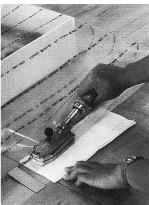
(13) 9.2 Cited references. 114. 9.3 Communications. 125. 9.4 Consulted internet links. 125. 9.5 Further reading. 126. 10 ANNEXES. 137. 10.1 Annex I: CD-R (Excel tables related to the experimental work) 10.1.1 Plastic boxes. CD-R CD-R. TM. box. CD-R. TM. box. CD-R. 10.1.1.1 Air exchange rate Curver 10.1.1.2 Air exchange rate Rondo 10.1.1.3 Life-time plastic boxes 10.1.2 Quantifications. 10.1.2.1 Quantification akaganéite 10.1.3 Results sample groups (FT-IR, XRD). CD-R CD-R CD-R CD-R. 10.1.3.1 Results group A. CD-R. 10.1.3.2 Results group B. CD-R. 10.1.3.3 Results group C. CD-R. 10.1.3.4 Results group D. CD-R. 10.1.3.5 Results group E. CD-R. 10.1.3.6 Results group F. CD-R. 10.1.3.7 Results group G. CD-R. 10.1.3.8 Results group H. CD-R. 10.1.3.9 Results group I. CD-R. 10.1.3.10 Results group K. CD-R. 10.1.3.11 Results group L. CD-R. 10.1.4 RP-A oxygen absorber. CD-R. 10.1.4.1 Oxygen-absorption capacity. CD-R. 10.2 Annex II: Explanations on some calculations, dataloggers, methods and materials used (in alphabetical order) 10.2.1 Air exchange rate (AER) / Carbon dioxide meter TM. 10.2.2 ESCAL. barrier film. 138 138 143. 10.2.3 Hanwell datalogger: rh-t bug / Measurement of relative humidity and temperature. 143. 10.2.4 Heat sealer / Sealing of plastic bags. 144. 10.2.5 Iron chloride tetrahydrate (FeCl2·4H2O) powder. 144. 10.2.6 Iron (Fe) powder. 145. 10.2.7 Leak detector / Leakage. 145. 10.2.8 Oxygen measurements. 146. 10.2.9 Oxygen transmission rate (OTR). 147. 10.2.10 Radio telemetry system Meaco / Measurement of relative humidity and temperature. 147.
(14) 10.3 Annex III 10.3.1 Samples and their preparation. 148 148. 10.3.1.1 Synthetic samples. 148. 10.3.1.2 Archaeological samples. 148. 10.3.1.3 Correspondences. 151. 10.3.2 Tested storage systems: used materials. 157. 10.3.2.1 Dry, cold and dry/cold storage. 157. 10.3.2.2 Oxygen-free storage. 157. 10.3.3 Monitoring of test environments. 158. 10.4 Annex IV 10.4.1 Questionnaire on storage of archaeological iron in Switzerland. 163 163. 10.4.1.1 Questions. 163. 10.4.1.2 Answers. 164. 10.5 Annex V 10.5.1 Suppliers of materials and equipment (alphabetical order). 168 168.
(15) 1 INTRODUCTION 1.1 General introduction to the topic The conservation of archaeological iron comprises many aspects as excavation, treatments, storage and long-term conservation. This works’ starting position is to examine one problem involved with freshly excavated iron artifacts: the danger of active corrosion after excavation. The aim is to find storage methods applicable for the time interval between the excavation of the objects and their arrival in a laboratory where a further treatment could be carried out or where long-term packaging would be prepared. How could active corrosion be prevented directly after excavation, where the corrosion process often starts? Many iron objects suffer from active corrosion once they are unearthed. On drying at the air cracks and fissures can form in the corrosion layers and oxygen and moisture can get free access to the core of the artifacts. Active corrosion of archaeological iron is characterised by the appearance of the iron oxyhydroxide akaganéite (β-FeOOH), an orange-brown corrosion product, which is in the centre of our interest. Physical damage and disappearance of the remaining iron are indicators of this active corrosion that leads to cracking, exfoliating and ‘sweating’ of the artifact. Akaganéite (β-FeOOH) is a voluminous corrosion product that causes, even if only present in small amounts, large physical 1. damage.. The present work looks at Swiss storage methods of archaeological iron as well as new options. 2. 3. Archaeological samples from Switzerland and synthetic powder samples are used for testing. Dry storage is investigated, used in Switzerland as well as other countries. Oxygen-free storage using high 4. barrier plastic bags and oxygen absorbers is examined, even if not applied in Switzerland in this form.. It could be a new option for Swiss laboratories and this question is investigated. The storage methods 5. were chosen based on a questionnaire sent to ten Swiss conservation laboratories and by personal 6. interest . The reason why Swiss approaches are looked at is because this work is submitted in Switzerland where improvement of storage methods for iron objects is a concern. Incitation of further discussion on the topic is therefore of interest.. 1.2 Review Two main approaches have been followed until present to deal with active corrosion on archaeological iron: direct intervention by stabilisation or adapted storage by action on the environment surrounding the object. 1. TURGOOSE S., 1982 a, p97; KNIGHT B. 1982, p50-55; personal communication with David Thickett, English Heritage, 25/06/2006. 2 Roman nails from two Swiss excavations, Vindonissa and Fribourg (summer / autumn period 2005). 3 A mixture of equal amounts of iron (Fe) and iron chloride tetrahydrate (FeCl2·4H2O). 4 The Service Archéologique de l’Etat de Fribourg applies anoxic storage by means of flushing bags with nitrogen. 5 See annex IV for the questionnaire. 6 Oxygen-free storage in the form it is tested in this work is not mentioned by Swiss conservators as an option but seemed to be a possible alternative worth testing.. 1.
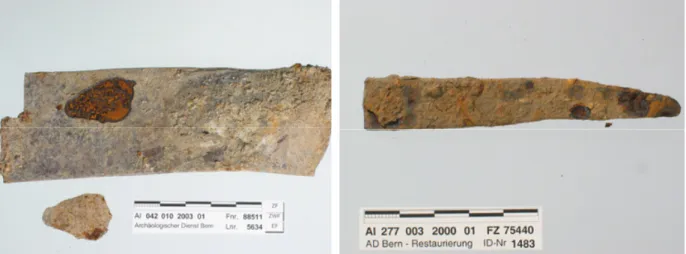
(16) Figure 1: An efficient storage method is needed to preserve iron artifacts for the future. This iron knife th blade, early 18 century AD, shows spots of active corrosion (Glassworks, Court (BE), Switzerland, excavation 2000). (Archaeological Office of the Canton of Bern, Switzerland).. Figure 2: Active corrosion can only be stopped or slowed down by means of efficient treatments or storage solutions (iron knife blade from the photo to the left). (Archaeological Office of the Canton of Bern, Switzerland).. Firstly, intervention to encounter the problem of active corrosion can be taken by treating the objects and trying to get the chlorides – that are responsible for the formation of akaganéite (β-FeOOH) – out of them. This can be achieved by stabilisation treatments of various natures (treatment with alkaline sulphite is a commonly used method in Switzerland, other methods like electrolysis, immersion in solutions of sodium hydroxide or lithium hydroxide, the Soxhlet treatment or the use of a hydrogen plasma treatment amongst others are – and were in the past – often more local traditions for treating objects). However, none of these methods has proven to be 100% effective and re-corrosion can occur when exposing the treated objects to unsuitable environments (e.g. high RH). This is due to remaining chlorides.. 7. The second possibility of prevention of active corrosion – which is also the topic of this work – is the intervention on the environment that surrounds the iron artifact. As mentioned above, access of moisture and oxygen are the major factors that cause active corrosion. By acting on those parameters corrosion can be slowed down. Many conservators apply dry storage to excavated iron and this can be achieved by placing the objects into microclimates where a desiccant is added (often silica gel is used). Some work has studied the efficiency of dry storage of archaeological iron to prevent formation of akaganéite (β8. FeOOH) and guidelines have been proposed for the level of desiccation. It has been stated, that 9. levels of 15-20% RH are needed to successfully prevent the formation of akaganéite (β-FeOOH).. On the other hand, the use of anoxic enclosures could be another option more and more taken into account because of the little maintenance it seems to need once objects packed. Corrosion can also be slowed down.. 10. Oxygen-free storage of archaeological iron has been applied by some conservators. 7. REGUER S., 2005, p12. WATKINSON D., LEWIS M., 2004, p88-102; WATKINSON D., LEWIS M., 2005, p241-252; THICKETT D., ODLYHA M., in press, 2006 ; SCOTT D. A., in press, p264; Museum and Galleries Commission, 1992, p57. 9 WATKINSON D., LEWIS M., 2004, p88-102; WATKINSON D., LEWIS M., 2005, p241-252. 10 MATHIAS C., RAMSDALE K., NIXON D., 2004, p28. 8. 2.
(17) 11. using different oxygen absorbers.. A recent trend is to choose RP-System. TM. oxygen absorbers from. 12. Mitsubishi Gas Chemical Company , and they will be used in this project.. 1.3 Choice of materials submitted for testing In the present work, synthetic powder samples and archaeological Roman nails from two Swiss excavations are submitted to two different storage methods, trying to find out which of those is most efficient preventing active corrosion after excavation. On one hand, the storage in dry and cold and dry/cold microclimates is examined. Samples are packed in resealable PE bags. 13. placed into PP boxes. Silica gel is added as a desiccant and. temperature either ambient or at 4°C. The combination of dry and cold conditions doesn’t seem to have been examined but is used by some conservators in Switzerland.. 14. The second method involves packing in anoxic enclosures. Here, the Revolutionary Preservation System. TM. from Mitsubishi Gas Chemical Company is examined. Two different oxygen absorbers (RP-. A and RP-K) are tested and compared. No work has examined in detail what exactly happens to the iron material during oxygen-free storage on the side of corrosion (which corrosion products would really form). Monitoring and analysis of the corrosion products formed in the submitted samples are carried out using FT-IR and XRD as well as optical microscopy. The results are compared on the amount of akaganéite (β-FeOOH) formed. Other aspects taken into account are the cost of the methods (in terms of material and time for monitoring) and the easiness of application.. 1.4 Research project aims and objectives Preventing active corrosion of archaeological iron by means of efficient storage methods is the topic of this work. The main question of this work always is, if there is formation of akaganéite (β-FeOOH), the sign of active corrosion. A storage method would be judged good and efficient, if no akaganéite (β15. FeOOH) formed over the test period of five-and-a-half months.. XRD and FT-IR are used to monitor. the samples over five-and-a-half months and this is used to make clear which of those techniques is more reliable in the detection of akaganéite (β-FeOOH) in its early stage. How exactly an iron object would react in the chosen storage environments? Would the combination of the cold and the dry bring any advantages over the use of simple dry storage? What changes would oxygen-free storage using the oxygen absorbers RP-A and RP-K from Mitsubishi Gas Chemical. 11. MAEKAWA S., ELERT K., 2003. REBIERE J., MOUREY W., FRANCOISE J., SIDOT E., 1998, p248-252; BECKER H., 1999, p72-76; GREIFF S., BACH D., 2000, p327; MATHIAS C., RAMSDALE K., NIXON D., 2004, p28-41. 13 Differences in closing or leaving the bags open are looked at. 14 See annex IV for details. 15 As the test period was of only five-and-a-half months, the evaluation ‘good’ can of course only be proven for this time period. However, tendencies can be presumed for the long term. 12. 3.
(18) Company cause in the submitted samples? Would akaganéite (β-FeOOH) really not form under these TM. conditions? And what was the difference between the two absorbers from the RP-System ? Many Swiss conservators have problems with the storage of big amounts of archaeological iron. A lot of those objects are not thought to be taken out of the stores on a regular basis but seem rather to be forgotten or not enough important to be put on display. But these objects need to be conserved to be available for study to the future generations. For this important number of objects, an efficient method of storage is needed: little monitoring (as staff is not always available), efficient prevention of corrosion over a long period, cost-efficiency and an easy way of applying the packaging technique are requested. Also it seems that the formation of akaganéite (β-FeOOH) occurs quickly after excavation. We therefore need a way to pack objects on site and keep them free of active corrosion until they arrive at the laboratory for treatment or long-term packaging. The work leads to conclusions on the efficiency of the storage methods in preventing active corrosion on freshly excavated iron objects. Costs and possibilities of applications are considered and advice could be given on efficient storage after this research.. 4.
(19) 2 CORROSION OF ARCHAEOLOGICAL IRON 2.1 Corrosion phenomenon This chapter provides information about the corrosion reactions of iron during burial and after excavation. Stress will be put on the influence of chlorides in these processes, as they are a main factor for the development of akaganéite (β-FeOOH), a brown to bright yellow corrosion product that forms after excavation of the artifact. No further referral will be carried out to burial environments, the emphasis of this chapter being on the main corrosion reactions taking place in any buried iron artifacts. A small part on marine cast iron has been added, as this material has to be differentiated from wrought iron.. Figure 3: The spalling of corrosion layers due to active corrosion is visible on this blowpipe (iron, th early 18 century AD, Glassworks Court in the canton of Bern, Switzerland, excavation 2001). (Archaeological Office of the Canton of Bern, Switzerland).. Figure 4: Active corrosion on a knife blade (iron, th early 18 century AD, Glassworks Court, excavation 2003). (Archaeological Office of the Canton of Bern, Switzerland).. 2.1.1 Corrosion during burial Barkman said in 1975: „The extent of corrosion is to a high degree dependent on the environment. In archaeological contexts a distinction must be made between corrosion in maritime environment, in air and in soil. A metal corrodes if it is exposed simultaneously to oxygen and water. Corrosion takes place electrochemically, as the corrosion medium is an electrolyte. The dissolution of the metal is an anodic process occurring simultaneously with a cathodic process in which oxygen, and sometimes hydrogen ions, are consumed.”. 16. The author underlined that in the deep soil where only little oxygen is. available corrosion would be slower.. 17. This statement brings us directly to our focal point. Corrosion of. iron artifacts during burial and after excavation is a complex phenomenon. Many aspects have to be 18. 19. considered. The characteristics of the soil , the climate and geographical region , the state of the. 16. BARKMAN L., 1975, p169. Ibid. 18 SCHARFF W. et al., 2000, p41. 19 Ibid., p48. 17. 5.
(20) artifact before and after burial, influences of deterioration agents such as water, oxygen or temperature. The type of object we are dealing with is also significant. Is it a marine cast iron artifact or a wrought iron object from a terrestrial site? Gerwin mentioned that the three main aspects influencing the corrosion process during burial were the amount of water and oxygen available, the acidity (pH-levels) and the amount of dissolved salts in the soil.. 20. 21. Réguer confirmed this statement.. An iron object is usually covered with an oxide film during its ‘life-time’. Later, when the artifact is buried, this film is no longer protective. In the presence of an aqueous electrolyte in the soil, corrosion takes place.. 22. Electronic conductivity between the anode and the cathode in the solid part, and ionic conductivity in the solution are required for corrosion of the iron to take place. Anions and cations carry the current between the anodic and cathodic sites. The solution surrounding and embedding the iron always ‘aspires’ to be neutral, so if there are too many anions, ferrous ions have to be produced to counterbalance the reaction.. 23. 24. The main chemical reactions found in this corrosion process are: 2+. Fe. -. ↔ Fe. + 2e. (anodic half reaction) 3+. Which can then be further oxidized to Fe 2+. Fe. 3+. in the following way:. -. ↔ Fe. Equation 1. + 1e. Equation 2. To this oxidation reaction there needs to be the reducing counterpart (oxygen reduction or hydrogen evolution): -. O2 + 2H20 + 4e ↔ 4OH +. -. (cathodic half reaction) or. -. O2 + 4H + 4e ↔ 2H2O +. Equation 4. -. 2H + 2e ↔ H2 -. 2H2O + 2e ↔ H2 + 2OH. Equation 3. or. Equation 5. -. Equation 6 25. It seems that hydrogen evolution takes places in low-pH environments (4 and below).. Turgoose stated that the first reaction, oxygen reduction, was the most significant during burial.. 26. Gerwin said that the occurrence of either oxygen reduction or hydrogen evolution was dependent on the pH-value and the access of oxygen.. 27. 20. GERWIN W., 1999, p174-175. REGUER S., 2005, p15, p17, p19. 22 SELWYN L. S., SIROIS P. J., ARGYROPOULOS V., 1999, p217-218. 23 TURGOOSE S., 1993, p37. 24 SELWYN L. S., SIROIS P. J., ARGYROPOULOS V., 1999, p217-218. 25 Ibid., p218. 26 TURGOOSE S., 1993, p37. 27 GERWIN W. 1999, p173. 21. 6.
(21) The oxidation of iron would then be as follows tells us Selwyn, if one takes into account Turgoose’s 28. statements:. 2+. Fe + ½ O2 + H2O → Fe +. 2+. + 2OH. -. Equation 7. + H2O. Equation 8. Fe + ¾O2 + ½H2O → FeO(OH). Equation 9. Fe + ½ O2 + 2H → Fe Or following Pötzsch:. 29. In these equations we can see that the initial corrosion product from which all following reactions will start is the ferrous ion.. 30. Gerwin provided further formulas to understand the ongoing corrosion reactions in the soil: 2+. 2Fe. 3+. 2Fe. +. 3+. + ½O2 + 2H ↔ 2Fe. + H2O. Equation 10. +. Equation 11. + 4H2O ↔ 2FeOOH + 6H. 2+. 31. -. Reaction between ferrous ions (Fe ) and hydroxyl ions (OH ) can take place easily on the metal surface in the beginning, where anodic and cathodic sites are located. Iron hydroxide, Fe(OH)2, is 2+. formed and constitutes a passivating film. Later, Fe. ions can undergo secondary reactions as they 2+. +. diffuse away from the anodic surface. Concentrations of Fe , O2, H and other anions affect these reactions. Iron hydroxide, Fe(OH)2, and ferrous hydroxychloride, β-Fe2(OH)3Cl, can form at lowoxygen levels. Partial oxidation of these will lead to the so-called ‘green rusts’ (these are further 32. oxidized to iron oxyhydroxides ). These species include other anions as chlorides or sulphates. Under 2+. high oxygen levels and low pH levels (less than 6), Fe 2+. lower the oxidation rate of Fe. remains in solution. Acidic environments. 3+. to Fe . If the same environment has a pH greater than 6, then iron(II). hydroxide, Fe(OH)2, will form and be oxidized and hydrolysed to iron(III) hydroxide, Fe(OH)3. Fe(OH)3 can further transform to goethite, α-FeOOH, while losing water. An important aspect in the corrosion process is that the anodic and cathodic sites get separated more and more. In the end, the cathode is situated at the outermost electrically conducting material, the anode on the metal surface. Around the anodic region, the environment becomes acid and rich in chlorides: the pores of the corrosion products get filled with an acidic iron(II) chloride solution (FeCl2-solution). Chloride ions will diffuse into 2+. the object as long as Fe. 33. ions are liberated in the corrosion process.. Turgoose advised to use a thermodynamic approach in regarding corrosion products that might be formed on buried iron. Taking a Potential-pH diagram for iron, Turgoose determined goethite, αFeOOH, and magnetite, Fe3O4, to be the stable solid corrosion products formed in natural environments. Other compounds may be present under specific conditions.. 34. 28. SELWYN L. S., SIROIS P. J., ARGYROPOULOS V., 1999, p218. PÖTZSCH A. in: SCHARFF W. et al., 2000, p26. 30 TURGOOSE S., 1993, p38. 31 GERWIN W., 1999, p173. 32 SELWYN L. S., 2004, p295. 33 SELWYN L. S., SIROIS P. J., ARGYROPOULOS V., 1999, p218-219. 34 TURGOOSE S., 1993, p39. 29. 7.
(22) In a few words the use of the Potential-pH diagrams will be explained, also called Pourbaix Diagrams (named after Marcel Pourbaix who developed the ideas), often taken into consideration to find out about the potential danger of an environment in which the metal object remains. Scharff et al. give a short explanation: „Die Metallkorrosion wird unter anderem stark von der Oxidationskraft (Redoxpotential) und dem pH-Wert der Umgebung beeinflusst. Aus Potential-pH-Wert-Diagrammen Pourbaix-Diagrammen). kann. (sog. abgelesen. werden, ob bei den momentan herrschenden Potential-pH-Bedingungen. Korrosion. stattfindet, und, wenn das der Fall ist, welche Korrosionsprodukte gebildet werden können. Ferner kann abgeschätzt werden, ob eine leichte Veränderung eines Parameters (z.B eine Absenkung des pH-Wertes) zu einer Gefährdung. führen. kann.”. 35. The. author. explains that the corrosion of metals depends on the redox-potential and the pH level of the surrounding environment.. Figure 5: Pourbaix Diagram (of 1966) of the iron – water system at 25°C with zones of immunity, passivation and corrosion. (SCHARFF W. et al., 2000, p28).. The Pourbaix Diagram shows us whether, at the given conditions of potential-pH, corrosion could take place and which corrosion products are formed. One can also read from the diagram whether a slight change in one of the parameters (as the pH) will bring danger to the metal. Pourbaix Diagrams explain the behaviour of metals in aqueous solutions (Potential versus pH).. 36. In the diagram, the. pH is noted on the x-axis, the potential on the y-axis. This means that the left side of the diagram represents an acidic, the right side the alkaline environment. The upper part shows 37. an oxidising and the lower part a reducing environment.. Pourbaix himself said of his model in 1971 that it could give us a ‘thermodynamic framework’ for all chemical and electrochemical. processes. occurring. during. corrosion.. Conditions of thermodynamic stability could be expressed. These graphs could be used to generate other graphs, specific to a metal and its general conditions of corrosion. Figure 6: The iron – NaCl (1M) system at 25°C: zones of corrosion and passivation are different than for the water – iron system. (NORTH N. A., PEARSON C., 1975 b, p181).. 35. SCHARFF W. et al., 2000, p20-21. VERINK E. D., 1968, p371. 37 REGUER S., 2005, p17. 36. 8.
(23) (stability of a dissolved species), to express immunity (stability of the metal) or passivation (stability of 38. solid oxides or salts).. Regarding an archaeological iron artifact one can say that it is covered by a layered structure of corrosion products. The outer layer contains heterogeneous elements such as sand, soil minerals, clay and small rocks. A congregation of iron corrosion products (such as goethite, α-FeOOH) is mixed to these elements. Under this layer, other corrosion products of a lower oxidation state (such as magnetite, Fe3O4) lie on the remaining metal.. 39. Of course the nature of the corrosion products can vary, according to the environment in which the artifact has been buried. For marine cast iron, we can find some other details regarding their corrosion reactions. Recovered marine cast iron usually consists of a metal core surrounded by graphitized corrosion products. The border between corroded and uncorroded zones cannot always be easily determined. Sometimes no metal will be left. On a partly corroded object, one can usually find water, iron oxyhydroxide (FeO(OH)), iron chlorides, silica (SiO2) cementite (Fe3C) and graphite in the graphitized corrosion products.. 40. Cast iron from the sea, compared to wrought iron, remains solid when corroded. This is even the case if the artifact is totally corroded. Ferrous concretion surrounds the object. Under this concretion, the surface of the corroded artifact is soft. In these objects, the graphite of the grey cast iron acts as a cathode and the iron as the anode. Remaining iron oxides and carbonates are held in place between the graphite flakes. Thanks to this, the shape of the object, in its mineralized form, is preserved. A so preserved object is called ‘graphitized’.. 41. Gilberg and Seeley provided evidence of corrosion products present on marine cast and wrought iron. They could detect small amounts of iron(III) chloride (FeCl3), iron(II) chloride (FeCl2), green rust, magnetite (Fe3O4), goethite (α-FeOOH) and iron sulphides (for anaerobic conditions). The presence of 42. iron oxychloride, (FeOCl) was doubted by these authors.. North added that basic iron(II) chlorides (α-. , β2- or γ3-Fe(OH)2·FeCl2) might be present in marine iron corrosion products.. 43. Selwyn mentioned that corroded marine iron is usually covered by calcium carbonate (CaCO3). She stated that the Fe. 2+. ions in this case rather react in the concretion layer than on the surface of the. object. Selwyn also added that wrought iron in marine environments would have the characteristic fibrous structure when recovered whereas cast iron would keep its original shape in the porous matrix of soft graphite.. 44. 38. POURBAIX M. in: AILOR W. H., 1971, p661. SELWYN L. S., 2004, p295. 40 NORTH N. A., 1987, p212. 41 CRONYN J. M., 1990, p185. 42 GILBERG M. R., SEELEY N. J., 1981, p50-56. 43 NORTH N. A., 1982, p80. 44 SELWYN L. S., 2004, p295. 39. 9.
(24) However, Turgoose stated that whatever the burial environment, the cause of damage to excavated artifacts was the same. „Difference between, for example, marine sites and soil burial are only of magnitude and not of type.”. 45. 2.1.2 Post-excavation corrosion The presence of an iron(II) chloride solution (FeCl2-solution) in the pores of excavated iron artifacts seems to be a major problem in the post-excavational corrosion. If oxygen and moist air have suddenly access to the unearthed object, damaging corrosion reactions can take place, leading, in the worst case scenario, to the complete loss of the artifact. Conversion of the iron(II) chloride solution becomes possible due to this access of oxygen and humidity. This chapter will elucidate these phenomena and take a look back at some theories that led to the present understanding of corrosion phenomena. In 1924 Evans said that for corrosion to take place on iron objects, water must be present in some form. He mentioned that heavy corrosion could be seen on iron where it was exposed to big changes in the temperature (day and night changes). The author also pointed out that acid gases could influence corrosion behaviour. He said that iron objects in the urban atmosphere where a lot of sulphur dioxide was present (use of coal as fuel) corroded more quickly than in a rural environment. Corrosion was accentuated when water was present. The presence of salt on iron surfaces accelerated the corrosion. Objects with this problem showed drops of liquid containing chlorine when exposed to moisture. The drops later became coated with a film of rust. Evans said that if the air was pure and moisture present, corrosion would be very slow. That iron did not rust if placed in the high mountains was explained by the author as being so because of low temperatures and high purity of the air. When Evans exposed iron to moist hydrogen chloride (HCl), he found that iron(II) chloride (FeCl2) was formed. This further oxidized in air to ferric hydroxide (Fe(OH)3) and iron(III) chloride (FeCl3) and gave the surface a damp appearance.. 46. However, the presence of salt needed to be connected to the presence of water and the amount of oxygen available in order to have more indications of the intensity of the corrosion. If the object was immersed in water, then oxygen was the controlling factor, if the object was kept at atmospheric 47. conditions, then moisture would be the controlling factor.. Evans also took up the work of W. H. J. Vernon, who dealt with similar questions in the same years. The latter said that if rust was present on iron and the object exposed to high humidity, the rust stimulated subsequent rusting.. 48. In a later publication, Evans mentioned that rust could only be. protective if it didn’t contain ferrous salts (iron(II) chloride and ferrous sulphate).. 49. 45. TURGOOSE S., 1993, p47. EVANS U. R., 1924, p128-134. 47 EVANS U. R., 1948, p75. 48 EVANS U. R., 1924, p143. 49 EVANS U. R., 1960, p505. 46. 10.
(25) Evans provided models to explain his theories. He placed a drop of potassium chloride solution (KCl) on the surface of an iron sheet. He observed the formation of a membrane shortly after this, in a circle running round the drop. This membrane was first white. and. then. turned. brown. Liquid at the interior. Figure 7: Evans’ model of a drop of potassium chloride solution on iron with formation of ferrous salts at the interior of the drop. (EVANS U.R., 1948, p29).. of the membrane contained. ferrous salts. The liquid around the membrane was alkaline. Evans claimed that this was due to the formation of a cathodic zone at the outer parts of the drops once the oxygen had been used up in the centre of the drop. This was an immunizing zone. The inner zone was anodic. Where alkali and iron(II) chloride (FeCl2) met, a membrane of white ferrous hydroxide (Fe(OH)2) would form, later changing to 50. brown ferric hydroxide (Fe(OH)3).. Evans made a list of factors affecting the velocity of corrosion (such as nature of the dominant metal, internal stresses, characteristics of the grains, salts present in the liquid, temperature, etc.). They were called the controlling factors (factors that control the corrosion).. 51. He proposed a distinction of three types of atmospheric corrosion: ‘Dry’, ‘Damp’ and ‘Wet’, following the importance of reaction including water vapour on the metal surface. In the ‘Dry’ type (low humidity) moisture did not play a significant role. In the ‘Damp’ type (medium and high humidity) Evans said corrosion could become very harmful above 70% RH. However, he added that this critical value could be lower in certain cases. The presence of hygroscopic bodies on the iron surface could also bring down the critical value. For ‘Wet’ atmospheric corrosion, the objects needed to be exposed to rain or 52. other sources of liquid water.. Near the sea iron could corrode heavily, to increasing extents the closer it was to the beach. This was related to the deposition of salts.. 53. All these reflections were important to understand what happened to iron objects exposed to harmful conditions. And the presence of salt was considered an important parameter. Arrhenius said in 1973: „The chlorides, mostly in the form of iron chloride, are the most dangerous enemy of iron. Iron chloride, which has entered into rust and iron on most artefacts is difficult to wash out and deliquesces. If water vapour is present, it is absorbed and the FeCl3 solution migrates to the iron, dissolves it and forms FeCl2. Under the action of oxygen from the air iron hydroxide is precipitated and FeCl3 is formed again. Heavy destruction of the iron in the form of pitting occurs.”. 54. North and Pearson discussed the role of water in combination with chlorides: „Corrosion will not occur in the absence of water but, as iron chloride is deliquescent, any dried artifact containing chlorides will. 50. EVANS U. R., 1924, p77; EVANS U. R., 1948, p29. EVANS U. R., 1924, p146. 52 EVANS U. R., 1960, p481-484. 53 Ibid., p504. 54 ARRHENIUS O., 1973, p2. 51. 11.
(26) extract moisture from the atmosphere and so form a very corrosive solution with a high chloride content.”. 55. Today, it is the model proposed by Turgoose in 1982 that is widely accepted.. 56. He said that at the. moment of excavation, the solid corrosion products present on the iron artifact were mostly magnetite (Fe3O4) and goethite (α-FeOOH), thermodynamically stable under burial conditions. Within pores of these layers, one could find an acidic solution containing ferrous ions and chloride ions (iron(II) chloride solution).. 57. After excavation, if the object was exposed to humidity and oxygen, one could see it break up and a 58. reddish-brown powdery deposit could appear. This deposit consisted of akaganéite (β-FeOOH).. A. solution of ferrous, ferric and chloride ions, of yellow colour and a very acid nature could sometimes 59. be present in combination with akaganéite (β-FeOOH).. Turgoose stated that for the formation of akaganéite (β-FeOOH) at room temperature ferrous and usually chloride ions (halide ions) must be present. He described the following reaction: 2+. 4Fe. + O2 + 6H2O → 4FeOOH + 8H. +. 60. Equation 12. In zones of active corrosion on iron artifacts, Zucchi et al. could already establish the presence of akaganéite (β-FeOOH) in 1977. The corrosion was accelerated on remaining metallic iron if akaganéite (β-FeOOH) was present. The main actor in this corrosion was seen to be chloride ions.. 61. Refait, Génin.and Ståhl et al. found that akaganéite (β-FeOOH) was a symptom of high chloride concentrations and an acidic environment.. 62. Coming back to the model of Turgoose, we can say that the solution of iron(II) chloride present at the moment of excavation will dry and crystallize to iron(II) chloride tetrahydrate (FeCl2·4H2O). If at this moment moist air has access to the object, the FeCl2·4H2O will transform to solid akaganéite (βFeOOH) and a solution containing ferrous, ferric and chloride ions. If metallic iron is present with the iron(II) chloride, this transformation under moist air will be rapid.. 63. To locate where akaganéite (β-FeOOH) was formed in this corrosion process, Turgoose gave us some indications. He said that ferrous ions diffused away from the metal surface and met oxygen coming in from outside. As this reaction was taking place under acidic conditions, other corrosion products could dissolve. If the pH was very low the solubility of the β-FeOOH would be important and 64. ferric ions remain in solution. This was known as the ‘weeping’ of artifacts.. 55. NORTH A., PEARSON C., 1975 a, p75/13/3.1. TURGOOSE S., 1982 a, p97-101; WATKINSON D., 1982, p28; MATHIAS C., 1999, p1845-1846; WATKINSON D., LEWIS M., 2004, p88-102; THICKETT D., ODLYHA M., in press, 2006. 57 TURGOOSE S., 1982 b, p6. 58 ZUCCHI F., MORIGI G., BERTOLASI V., 1977, p103-105; TURGOOSE S., 1982 b, p6. 59 TURGOOSE S., 1982 b, p6. 60 TURGOOSE S., 1982 a, p98. 61 ZUCCHI F., MORIGI G., BERTOLASI V., 1977, p103-105. 62 REFAIT P., GENIN J.-M., 1993, p797-819; STÅHL K., NIELSEN K., JIANG J., LEBECH B., HANSON J. C., NORBY P., VAN LANSCHOT J., 2003, p2563-2564. 63 TURGOOSE S., 1982 a, p98. 64 Ibid.; TURGOOSE S., 1993, p45. 56. 12.
(27) Another important insight was that if no iron core left in a corroded iron artifact then these reactions would not take place, as ferrous ions were a main partner for the formation of akaganéite (β65. FeOOH).. A new point added by Turgoose to the current knowledge at the time of his publication was his claim that excavated iron artifacts should be stored at RH levels as low as 20% or less to prevent ongoing reactions of FeCl2·4H2O and iron (which would not take place below 15% RH).. 66. The model proposed by Turgoose can to some extent be found in articles already published in 1969 and 1970 by Keller. He said that akaganéite (β-FeOOH) could for example be obtained by oxidation of a mixture of FeCl2·4H2O and ferrum reductum. The mixture was sprayed with water to transform it to akaganéite (β-FeOOH). He also observed akaganéite (β-FeOOH) being formed during pitting corrosion of iron when FeCl2·4H2O was in contact with metallic iron.. 67. To the same questions, Watkinson stated: „It has long been accepted that chlorides are one of the chief causes of continued corrosion in archaeological ironwork. As a consequence of this thinking most treatments aim to remove or inhibit chlorides contained within the artifacts. The form of this chloride has been variously suggested as iron(III) chloride (Plenderleith and Werner, 1971), or as βFeOOH in areas of active corrosion (Zucci, Morigi and Bertolasi, 1977), and as FeOCl in marine ironwork (North and Pearson, 1977). It has been suggested recently that the chlorides present at the time of excavation are probably in solution within the pores of the corrosion products (Turgoose, this volume).”. 68. Mathias could see the described reactions by Turgoose: „Observations presented here correlate with the model proposed by Turgoose since an iron oxide and iron oxyhydroxide phases have been identified in the corrosion layers. Cracking and spalling of artifacts in the post-storage environment, as well as chloride concentrations identified by elemental mapping, provide evidence for an akaganéite phase resulting after excavation and further oxidation.”. 69. 65. TURGOOSE S., 1982 a, p98. Ibid., p100. 67 KELLER P., 1969, p103, 108; KELLER P., 1970, p31. 68 WATKINSON D., 1982, p28. 69 MATHIAS C., 1999, p1845-1846. 66. 13.
(28) Figure 8: Active corrosion with akaganéite (β-FeOOH) formation leads to spalling of corrosion layers th (blowpipe, iron, early 18 century AD, Court (BE), Switzerland).. Figure 9: Cracking and spalling are visible signs for active corrosion (detail from the object to the left).. Selwyn et al. again took up the corrosion reactions described by Turgoose in 1982. They gave a very clear description of the model in action: „[…] the pores of corrosion products on freshly excavated iron 2+. +. +. are filled with an acidic FeCl2 solution, i. e., a solution containing Fe , FeOH and H ions charge-. balanced by Cl ions. If iron is excavated and allowed to dry, the acidic FeCl2 solution concentrates, the corrosion layers crack, and oxygen becomes readily available. The sudden supply of oxygen 2+. rapidly oxidizes the Fe. ions in solution. […]. Solid iron oxide hydroxides (FeOOH), more usually. called iron oxyhydroxides, precipitate, and the solution becomes more acidic.”. 70. It also became clear that as long as oxygen was available, the corrosion cycle involving an acidic solution with chloride ions could go on. This all could now explain why iron objects exposed to the air after excavation would be destroyed so rapidly. As iron oxyhydroxides increase in volume during formation, corrosion layers on an object may crack and further oxygen and moisture could access the depth of the object.. 71. Selwyn et al. gave more details on the phenomenon of ‘weeping’. It seemed true that a low pH of 1-3 2+. and the presence of ferrous ions (Fe ) and iron(II) chloride (FeCl2) mentioned by North 73. Turgoose. 72. and. were conditions occurring during ‘weeping’. Selwyn et al. thought the phenomenon was. due to the hygroscopic properties of the iron(II) chloride (FeCl2·4H2O crystals would act as deliquescent materials being able to absorb moisture from the air and dissolve to form a solution). 3+. Ferric ions (Fe ) were also observed in the solution formed during weeping. They might contribute to the deliquescence of the FeCl2·4H2O. ‘Weeping’ could leave behind solid spherical shells.. 74. The. authors identified goethite (α-FeOOH) and lepidocrocite (γ-FeOOH) as constituents of the shells, but no akaganéite (β-FeOOH). They said this might have been due to the experimental conditions used or that akaganéite (β-FeOOH) had initially formed and then transformed to goethite (α-FeOOH). The. 70. SELWYN L. S., SIROIS P. J., ARGYROPOULOS V., 1999, p219. Ibid., p220. 72 NORTH N. A., 1982, p75-83. 73 TURGOOSE S., 1982 a, p97-101. 74 SELWYN L. S., 2004, p296. 71. 14.
(29) authors said that compared to Turgoose’s observations of ‘weeping’ occurring away from metal 75. surface, they could find ‘weeping’ occurring only from a metal surface on outwards.. The authors said that akaganéite (β-FeOOH) could form on the iron/corrosion interface, at the place where iron(II). chloride. akaganéite. (FeCl2). (β-FeOOH). was was. concentrated. growing,. As. elongated. particles were formed and pressure put onto the overlying corrosion layers. These could then crack. To prevent these reactions, the authors advised removing the acidic iron(II) chloride solution because then chemical and physical damage could be stopped. Figure 10: Diagram of vertically growing, voluminous akaganéite (β-FeOOH). (SELWYN L. S., SIROIS P.J., ARGYROPOULOS V., 1999, p226).. 76. Once all metallic iron lost in the artifact, chloride ions would move out of it.. 77. Another important aspect mentioned was the fact that the corrosion of iron was dependent on temperature 78. (corrosion was much more important at 20°C than at 4°C).. Extensive research on the influence of the RH was carried out in 2004 by Watkinson and Lewis. They did some further tests on the model proposed by Turgoose, basing their results on gains in weight of their samples (see chapter 3.2.3). They found that iron in. combination. with. iron. chloride. tetrahydrate. (FeCl2·2H20) did not corrode at a RH of 19%. But if FeCl2·4H20 was mixed with the iron powder, the mixture gained weight at 22%, 27.5% and 35% RH. The corrosion of the iron in this case would be slow at 22% RH and speed up at 30% and 35% RH. If akaganéite (β-FeOOH) was present on the iron powder, corrosion Figure 11: Scanning electron micrograph of akaganéite (β-FeOOH). (SELWYN L. S., SIROIS P. J., ARGYROPOULOS V., 1999, p226).. could take place at 15% RH (at 12% RH no significant corrosion was visible).. 79. Thickett showed that the critical RH for pure iron(II). chloride to oxidise to akaganéite (β-FeOOH) was situated at about 18%. The increase of akaganéite (β-FeOOH) formation was dramatic from 30% RH upwards. The author was able to show that the presence of copper or humic acids increased the amount of akaganéite (β-FeOOH) formed while goethite (α-FeOOH) could reduce it.. 80. Lately another corrosion product forming in high chlorine-containing environments (chloride content of about 15-20 %mass) was detected in archaeological material: ferrous hydroxy-chloride (β75. SELWYN L. S., SIROIS P. J., ARGYROPOULOS V., 1999, p220-221. Ibid., p225-227. 77 SCHARFF W. et al., 2000, p26, p28. 78 Ibid. 79 WATKINSON D., LEWIS M., 2004, p88-102. 80 THICKETT D., 2004, p90. 76. 15.
(30) Fe2(OH)3Cl). As akaganéite (β-FeOOH), this corrosion product formed at the interface metal/oxide in the presence of chlorides. In zones with a high chloride concentration (15-20 %mass) preferably ferrous hydroxy-chloride formed whereas akaganéite (β-FeOOH) formed where 5-8 %mass of chloride in the corrosion zone was present.. 81. Regarding recovered marine cast iron we can cite North and Pearson: „Firstly, at room temperature, FeOCl will slowly convert to FeCl3 and FeO(OH) in the presence of water.”. 82. For wrought and cast iron. from the sea their analysis showed: „Our X-ray diffraction analysis of untreated wrought and cast iron corrosion products show that the iron is present predominantly as a mixture of magnetite (Fe3O4), iron oxy-hydroxide (FeO(OH)), iron oxy-chloride (FeOCl) and, in the case of cast iron, iron carbide or cementite (Fe3C).”. 83. The authors advice was to aim for levels of less than 100 ppm (parts per million). in chloride in the object’s corrosion layers after treatment and not go over a maximum of 200 ppm. This seemed to them a satisfactory level.. 84. North gave some indications on corrosion behaviour after recovery of marine cast iron objects. He said that if the object was allowed to dry out, then the chloride components would decompose to form hematite (Fe2O3), iron(III) chloride (FeCl3), hydrogen chloride (HCl) and iron oxyhydroxide (FeO(OH)). All these chemical products provided a good corrosion environment and if oxygen was available, 2+. corrosion could take place. Ferrous and ferric ions (Fe. 3+. and Fe ) in solution in the graphitized zones. precipitated to form iron oxyhydroxide (FeO(OH)) and magnetite (Fe3O4). The volume increase could cause the graphitized zone to crack. One should keep these objects wet to minimize access of oxygen to the graphitized layers and so oxygen reduction (the cathodic reaction) could be minimized.. 85. 2.1.3 Observed corrosion products on iron from soil burial site Neff introduced a terminology to describe the layers found on a corroded archaeological iron object. The model shows the metallic substrate (M), then a layer of dense corrosion products (CPD for ‘couche de produits denses’) composed of oxides and oxyhydroxides. Follows a zone of transition, which separates the CPD from the burial environment. This layer is the transformed environment (MT for ‘milieu transformé), containing soil elements and corrosion products. The soil layer (S) surrounds the whole system of layers.. 86. 81. REGUER S., DILLMANN P., MIRAMBET F., BELLOT-GURLET L., in press, 2005, p3-5. NORTH N. A., PEARSON C., 1975 b, p174. 83 Ibid. 84 NORTH N. A., PEARSON C., 1978, p179. 85 NORTH N. A., 1987, p212-213. 86 NEFF D. et al., 2005, p515-535. 82. 16.
(31) Figure 12: The different layers that can be found in an archaeological iron object: the metallic substrate with intern markers, a layer of dense corrosion products as oxides or oxyhydroxides followed by a transformed environment with elements of corrosion as well as soil components and a soil layer surrounding the whole. (REGUER S., 2005, p20).. Réguer told us about the corrosion products that had formed on iron objects in long-term burial conditions. Mainly goethite (α-FeOOH) was detected. Sometimes magnetite (Fe3O4) and maghemite (γ-Fe2O3) were mixed in the layer alongside goethite. Siderite (FeCO3) could form in de-aerated 87. environments.. 2.1.4 Some general reflections on evidence preserved in corrosion products and attitudes of conservators influencing further treatment success We shall finish this chapter with some more general reflections on corrosion layers, what information they might contain (affecting the choice of treatment) and on some aspects related to the way of dealing with excavated iron, which influences the forms of treatments after excavation. Turgoose published an article on evidence preserved in corrosion products (organic material, information on the original shape and surface, metallurgical structure, prediction of original composition, information about burial environment). Sometimes, he stated, no adequate analysis techniques had been developed yet to fully understand all the aspects. So it seemed tempting to the author to leave corrosion layers on the artifact for future researchers and the application of future techniques. As this was not always possible, Turgoose emphasized the fact that with the removal of corrosion layers, information about the artifact itself, its burial context and environment could be lost.. 88. Keene and Orton found out that the time-lapse between excavation and treatment might affect the 89. results of a desalination treatment.. This seemed to be a key factor for post-excavation corrosion of. iron artifacts. Regarding this aspect Greiff and Bach said that the removal of the chlorides out of the akaganéite (β-FeOOH) network was a slow process. The desalination could be much faster if there was no akaganéite (β-FeOOH) present. The iron chlorides in form of the iron chloride hydrates 87. REGUER S., 2005, p20-21. TURGOOSE S., 1989, p30-31. 89 KEENE S., ORTON C., 1985, p140. 88. 17.
(32) FeCl2·4H2O and FeCl2·2H2O were easier to remove (than akaganéite) even in a solution without 90. addition of alkalis and this removal could be achieved within a short period of time.. The protection of archaeological iron should start directly after excavation. Adequate storage is needed until treatment can be started. In the best-case scenario, the conservation and restoration 91. begin immediately on the freshly excavated artifacts.. 2.2 Akaganéite (β β-FeOOH) This chapter contains some basic information on the occurrence, the formation, the chloride content and the structure of β-FeOOH (mineral name: akaganéite). This iron oxyhydroxide, a corrosion product, is – as we have already seen – believed to cause major problems in the conservation of archaeological iron artifacts. For more detailed information on the formation, structure and characteristics of akaganéite (β-FeOOH) one can refer to the following publications: MACKAY A. L., 1962; KELLER P., 1969 and 1970; FEITKENCHT W. et al., 1973; CHILDS C. W. et al., 1980; GONZALES-CALBET J. M. et al., 1981; SELWYN L. S. et al., 1999; STÅHL K. et al., 2003; POST J. E. et al., 2003; WATKINSON D., LEWIS M. T., 2005; REGUER S., 2005 (this author gives an exhaustive list of further publications).. 2.2.1 Occurrence 92. β-FeOOH (akaganéite) was produced synthetically first in 1925 by J. Böhm , who thought it was a new form of iron(III) oxide hydrate. 1935 by Weiser and Milligan.. 94. 93. Synthetic β-FeOOH (akaganéite) was first identified by XRD in. The compound was named β-FeOOH (as against α- and γ-FeOOH). and presented as an iron oxyhydroxide rather than an iron(III) oxide hydrate. -. - 96. fluorine ions (F ) or chlorine ions (Cl ).. 95. β-FeOOH can contain. It has also been possible to produce chloride-free β-FeOOH. 97. (akaganéite).. Later than its synthetically obtained form β-FeOOH, the mineral akaganéite was discovered in 1961 by Dr. M. Nambu in the Japanese limonite mine Akagane. The mineral was named akaganéite after the 98. location of the mine (we can also find this name applied to the synthetic form β-FeOOH). mineral akaganéite (β-FeOOH) is free of chloride.. 99. The. Akaganéite (β-FeOOH) is a weathering product. 90. GREIFF S., BACH D., 2000, p324. SCHARFF W. et al., 2000, p362. 92 BÖHM J., 1928, cited in: GALLAGHER K. J. et al., 1969, p465-470. 93 KELLER P., 1969, p103; GALLAGHER K. J., 1970, p1225. 94 WEISER H. B., MILLIGAN J., 1935, cited in STÅHL K. et al., 2003, p2565; SELWYN L. S., SIROIS P. J., AGYROPOULOS V., 1999, p223. 95 KELLER P., 1969, p103. 96 MACKAY A. L., 1960, p551. 97 FEITKNECHT W. et al., 1973, p2847; DEGRIGNY C. et al., 1999, p34. 98 MACKAY A. L., 1962, p270. 99 KELLER P., 1969, p103; FEITKNECHT W. et al., 1973, p2847. 91. 18.
(33) and has also been observed in meteorites, on rock art, on iron exposed to a marine atmosphere and on archaeological iron.. 100. 2.2.2 Structure 3+. Réguer detailed that in the structure of akaganéite (β-FeOOH), each Fe. ion was surrounded by six. atoms of oxygen and/or hydroxyl groups, forming an octahedron (see figure 13). These octahedra are linked to each other sharing edges and corners to form double chains that are parallel to the b-axis. The double chains in turn are linked with other double chains via the tops of the octahedra. This creates a cavity (also called channel or tunnel. 101. -. -. ) in which Cl ions or F ions, hydroxyl. groups or water molecules can be trapped to stabilize the structure (see figure 14).. 102. Chlorides can be adsorbed on the surface area of akaganéite (β-FeOOH) and eventually be released in 103. washing off.. When the chloride content is smaller, less. Figure 13: The octahedron-structure described by Réguer, the distances between the iron ions are given. (MANCEAU A. et al., 1988, cited in: REGUER S., 2005, p32).. chloride can be found adsorbed in the akaganéite (βFeOOH). The structure of the compound is not influenced by this surface adsorption of chloride ions. These chlorides can be adsorbed via substitution of OH-groups in the octahedra on the surface of the compound. If there are fewer chloride ions in the structure the unit cell in the crystal structure becomes smaller and the octahedra deformed (Réguer could see this in the changes of the aand b-values with the help of XRD). The adsorptionchlorine can leave the compound more easily than the structural chlorine. It is not known if all the chlorine can be removed from the compound without a break-down of its 104. structure.. Watkinson et al. claimed the internal (or. Figure 14: Structure of akaganéite (βFeOOH) with chlorides (large circles) and hydrogens (small circles) in the tunnel region. (POST J. E., et al., 2003, p783). 105. structural) chloride could only be removed by decomposition of the akaganéite (β-FeOOH).. Akaganéite (β-FeOOH) remains stable up to 200°C. The chlorides released during washing are the 106. chloride ions adsorbed at the surface of the akaganéite (β-FeOOH) particles. 100. SELWYN L. S., SIROIS P. J., AGYROPOULOS V., 1999, p223. 2 The tunnel measures 5 x 5 Å (two octahedra each side). (REGUER S., 2005, p31). 102 REGUER S., 2005, p31. Ståhl et al. gave the most recent description of akaganéite (β-FeOOH), claiming it could be proved to be monoclinic with space group I2/m, a = 10.6000Å, b = 3.0339Å, c = 10.513Å and β = 90.24°. (STÅHL K. et al., 2003, p2565). 103 STÅHL K. et al., 2003, p2574. These chlorides are mobile and can corrode iron in contact with the akaganéite, β-FeOOH. (WATKINSON D., et al., 2005, p81). 104 REGUER S., 2005, p93, p 119, p120, p178. 105 WATKINSON D., LEWIS M. T., 2005, p242. 106 STÅHL K. et al., 2003, p2574. 101. 19.
Figure
+7
Documents relatifs
This study presents the isotopic compositions and concentrations of dissolved and particulate iron from two seawater profiles of the western and central equatorial Pacific
In order to determine the impact of O 2 contamination on the test solution, several permeation tests were conducted with continuous pH measurement and periodic sampling of
It is also observed that the permeation current density decreases in the presence of oxygen, which is rather surprising given the decrease in pH which is also observed, and
The analysis of impedance data also allowed determining the evolution with time of the charge transfer resistance, from which the corrosion current density could directly
The physiological status of Douglas fir seedlings and the field performance of freshly lifted and cold stored stock.. Conor O’Reilly, Nick Mccarthy, Michael Keane,
A combination of electron microscopy, X-ray and neutron spectroscopies and computational methods has provided new insights into the species present on the surface of freshly
L’archive ouverte pluridisciplinaire HAL, est destinée au dépôt et à la diffusion de documents scientifiques de niveau recherche, publiés ou non, émanant des
reported increased mitochondrial iron levels in HEK SFXN2 KO cells [9], an ICP-MS analysis did not show significantly modified cellular or mitochondrial iron levels in HEK SFXN1
