Architecting Complex Systems for Robustness
ByJason C. Slagle
B.S. Aerospace Engineering The Pennsylvania State University, 1997
Submitted to the System Design and Management Program In Partial Fulfillment of the Requirements for the Degree of
Master of Science in Engineering and Management at the
Massachusetts Institute of Technology
February 2007
C 2007 Jason C. Slagle. All Rights Reserved.
The author hereby grants to MIT permission to reproduce and to distribute publicly paper and electronic copies of this thesis document
in whole or in part in any medium now known or hereafter created.
Signature of Author:
S JasoYC. Slagle System Design and M 4agement Program
Fo f '; 2007 Certified by:
Daniel 9
4Trey
Associate Professor of Mechanical Engineering and Engineering %ystems Thesis Supervisor
Certified by:
Edward F. r wley Professor of Aeronautics and Astronautical Engineering System
/ , ThesiSu S6 sbI
Accepted by:
(/"ac]k Hale Director System Design and Management Program
ARCHVES
MASSACHUSETTS iNSTnTUTE
OF TEOHNOLOGY
MAY 0 6
2008
LIBRARIES
Abstract
Architecting Complex Systems for Robustness
byJason C. Slagle
Submitted to the System Design and Management Program February 2007 in partial fulfillment of the
Requirement for the Degree of Master of Science in Engineering and Management
ABSTRACT
Robust design methodologies are frequently utilized by organizations to develop robust and reliable complex systems. The intent of robust design is to create systems that are insensitive to variations from production, the environment, and time and use. While this process is effective, it can also be very time consuming and resource intensive for an
engineering team. In addition, most robust design activity takes place at the detailed design phase, when the majority of the product life cycle cost has already been
committed. Addressing robustness and the "ilities" at the architecture level may be more effective because it is the earliest and highest leverage point in the product development process. Furthermore, some system architectures are inherently more robust than others.
In this thesis, a framework based on principles is proposed to architect complex systems for type I and II robustness. The principles are obtained by tracing the architectural evolution of the jet engine, which is an extremely complex system that has evolved to high reliability. This framework complements existing robust design methods, while simultaneously incorporating the robustness focus earlier in the product development process.
Thesis Supervisor: Daniel D. Frey
Title: Associate Professor of Mechanical Engineering and Engineering Systems
Thesis Supervisor: Edward F. Crawley
Acknowledgements
The last two years have passed unimaginably fast, and much has been accomplished. I owe many people thanks for the support they have given to make all of this possible. This passage is an attempt to show, in some small way, my sincere appreciation.
I would like to thank Dan Frey and Ed Crawley for their lectures in system engineering and system architecting respectively, which have significantly improved my
understanding of complex systems. They also provided much guidance, insight and feedback for this thesis.
MIT has taught me a great deal about the management of innovation, disruptive
technologies and technology strategy. I am grateful for the fascinating presentations in these areas by professors Ralph Katz, Eric von Hippel, Clayton Christensen, Olivier de Weck and James Utterback among others.
I would like to thank Pat Hale for the excellent leadership he has provided to the SDM program. Also, I would like to thank my team members Jeff Lloyd, Paul Braunwart,
Robbie Allen, Ben Entezam and Kevin Baughey for making numerous challenging projects both enjoyable and achievable.
I owe a debt of gratitude to all of my mentors, many of whom do not even realize they have this role. Their guidance has contributed considerably to my personal and professional development, and has further fueled my passion for technology and innovation.
My parents and family have supported me throughout my life and helped me to pursue my dreams. I am sincerely thankful and love you all.
Most importantly, I am grateful for the never-ending support and encouragement from my wife Elana. Thank you, and I love you.
Table of Contents
Abstract ... 2
A cknow ledgem ents ... 3
Table of C ontents ... 4
List of Figures ... 6
List of Tables ... 8
N om enclature ... 9
1. Introduction ... 13
1.1 Background and M otivation ... 13
1.2 Objectives ... 14
1.3 Research Approach... 15
1.4 Sources... 18
1.5 Structure of Thesis ... 19
2. Literature R eview ... 21
2.1 The Quality Literature ... 21
2.2 The System Architecture Literature... 25
2.3 The Com plex System s Literature... 26
3. System Architecture and Complex Systems... 28
3.1 System A rchitecture ... 28
3.3 Com plexity... 31
3.4 Com plex System s... 32
3.5 Em ergence ... 34
3.6 Principles and H euristics ... 36
3.7 Sum m ary ... 37
4. Robustness and Reliability ... 38
4.1 Robustness ... 38
4.2 Reliability... 40
5. Architectural Evolution of the Jet Engine... 42
5.1 Introduction... 42
5.2 Technical Overview of the Jet Engine... 42
5.3 Architectural Innovation... 49
5.4 D om inant D esigns... 51
5.5 A rchitectural Evolution... 54
5.5 Sum m ary... 68
6. Principles of Robust System Architecture... 70
6.1 Introduction to Principles of Robust System Architecture ... 70
6.3 M odularity ... 76 6.4 Feedback ... 84 6.5 Standardization ... 87 6.6 Redundancy... 90 6.7 Sim plicity... 93 6.8 Independence ... 96 6.9 Autonom y ... 98 6.10 Scalability ... 99
6.11 Sum m ary and Fram ework... 102
7. The Product Developm ent Process ... 104
7.1 The Product Developm ent Process ... 105
7.2 Robust System Architecting M ethodology... 107
7.3 Design for Six Sigm a... 111
8. Conclusions and Future W ork ... 116
8.1 Conclusions... 116
8.2 Future W ork... 118
Bibliography... 121
Appendix A. Technology Readiness Levels ... 129
Appendix B. Invention Levels ... 131
Appendix C. Jet Engines List ... 132
List of Figures
Figure 1. Robust Design in the Product Development Process (Modified from Fabrycky
and B lanchard, 1991) ... 14
Figure 2. Engine Reliability Trend ... 16
Figure 3. Engine Life on Wing Trend... 17
Figure 4. P-D iagram ... 23
Figure 5. Form -Function Relationship (Crawley, 2005) ... ... 29
Figure 6. Two Types of Aircraft Architecture (Modified from Cessna, 2006) ... 30
Figure 7. Evolution of Actual and Perceived Complexity (Crawley, 2005)... 34
Figure 8. Illustration of Emergent Use of a Product System... 35
Figure 9. Cross-Section of a Turbojet Engine (Century of Flight, 2006)... 43
Figure 10. GE90 Turbofan Engine (Modified from GE, 2006)... 43
Figure 11. Boeing 777-200LR Aircraft (Boeing, 2006) ... 44
Figure 12. Thrust-to-Weight Ratio Trend for GE Engines... 47
Figure 13. Specific Fuel Consumption Trend... 47
Figure 14. IFSD Rate for B727 with JT8D Engines... 48
Figure 15. Types of Innovation... 49
Figure 16. Architectural Innovation in Lawn Tractors ... 50
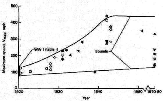
Figure 17. Trends in Maximum Speed of Propeller-Driven Aircraft (Donlan, 1954)... 53
Figure 18. Trend in Thrust Specific Fuel Consumption (Koff, 2004)... 56
Figure 19. GEnx Engine with Counter-rotating Spools (GE, 2006)... 57
Figure 20. Secondary Flow Systems for the GE90-94B Engine (GE, 2006) ... 59
Figure 21. Number of Engine Control Functions (Koff, 2004) ... 60
Figure 22. Evolution of Engine Controls (Jaw and Garg, 2005) ... 61
Figure 23. Jet Engine Total Part Count... 63
Figure 24. Number of Fan Blades for Large Turbofan Engines... 64
Figure 25. Number of Compressor Stages for Large Turbofan Engines... 65
Figure 26. Unique Part Numbers per Engine... 66
Figure 27. Architectural Evolution of Jet Engine... 68
Figure 28. Visualizing Stability...73
Figure 29. Engine Cross-Section Showing Fan Blades and Bearing Support (Doerflein et al., 2004) ... 75
Figure 30. Close-up of Bearing Support ... 76
Figure 31. Types of Modularity (Ulrich, 1995) ... 78
Figure 32. Propulsor Concept (GE, 2006) ... 79
Figure 33. P&W J57 Turbojet Engine (Pratt & Whitney, 2006) ... 81
Figure 34. The Off-Design Dilemma (Blanton, 2004) ... 82
Figure 35. Two-Spool Vs. One-Spool Architecture ... 83
Figure 36. Compressor Stall Map / Margin (Prasad, 2005)... 83
Figure 37. Trend toward Faster Feedback (Modified from Fey and Rivin, 2005) ... 85
Figure 38. Trends in the Number of Engine Sensors... 87
Figure 39. Boeing Study on 122 Maintenance Errors Occurring over 3 Years (Boeing, 1993) ... 89
Figure 40. Redundancy in the FADEC III Control Unit (Hispano-Suiza, 2006) ... 92
Figure 42. GE T700 Turboshaft Engine (GE, 2006) ... 95
Figure 43. T700 Compressor Blisk (DRS, 2006) ... 96
Figure 44. Types of Design Matrices (Suh, 1990)... 97
Figure 45. Line of Transition to Active Adaptive Systems ... 98
Figure 46. Types of Scaling for Elements ... 100
Figure 47. Types of Scaling for Connections ... 100
Figure 48. GE Commercial Engine Development (Joyce and Rosario, 2002)... 101
Figure 49. The Product Acquisition Process (CIPD, 2004)... 104
Figure 50. Generic Product Development Process ... 105
Figure 51. Spiral Development (Boehm, 1988)... 106
Figure 52. Generic Product Development Process (Crawley, 2005)... 107
Figure 53. Robust Architecting Methodology ... 108
Figure 54. System Architecture Framework for Upstream Influences (Crawley, 2005) 109 Figure 55. System Architecture Framework for Downstream Influences (Crawley, 2005) ... 1 10 Figure 56. Incentive to Architect for Robustness (modified from Soman, 2004) ... 112
Figure 57. Relative Cost of Correcting an Error (Frey, 2005)... 113
Figure 58. GE Design for Six Sigma Process (Soman, 2004) ... 114
List of Tables
Table 1. Information Sources for the Research ... 19
Table 2. Four Architecting Methodologies (Modified from Rechtin and Maier, 2002)... 36
Table 3. Definitions of Robustness (Santa Fe, 2001) ... 38
Table 4. Types of Robustness (Chen, et al., 1996) ... 39
Table 5. Examples of Architectural Innovation... 51
Table 6. Dominant Designs for Jet Engines... 52
Table 7. Sample Architectures that Are Excluded... 53
Table 8. Robust System Architecture Principles ... 71
Table 9. Evolution of the Number of Engine Sensors ... 86
Table 10. Principles in P-Diagram Framework ... 102
Nomenclature
AB AC ACC AD AFRL AIAA ALL APST APU ARINC ARIZ ASME ATO BIT Blisk BPR CAAM CDP CFD CFR CLM CMC COTS CPM CPRCTQ
DARPA DEEC DFC DFSR DFSS DMADOV DMAIC DMICS DoD DoE DoE DOF DP DSM EASA EBU ECS Afterburner Advisory CircularActive Clearance Control Airworthiness Directive
Air Force Research Laboratory
American Institute for Aeronautics and Astronautics Allison
Autonomous Propulsion Systems Technology Auxiliary Power Unit
Aeronautical Radio, Incorporated
Algoritm Reshenia Izobretatelskih Zadach (Algorithm for Inventive Problem Solving)
American Society of Mechanical Engineers Aborted Takeoffs
Built-In Test
Integral blade and disk Bypass Ratio
Continued Airworthiness Assessment Methodologies Committee Compressor Discharge Pressure
Computational Fluid Dynamics Code of Federal Regulations Component Level Model Ceramic Matrix Composite Commercial Off-The-Shelf Critical-Parameter Management Compressor Pressure Ratio Critical to Quality (Critical "Y")
Defense Advanced Research Projects Agency Digital Electronic Engine Control
Design for Changeability Design for System Reliability Design for Six Sigma
Define Measure Analyze Design Optimize Verify Define Measure Analyze Improve Control
Design Methods for Integrated Control Systems Department of Defense
Department of Energy Design of Experiments Degrees of Freedom Design Parameter Design Structure Matrix
European Aviation Safety Agency Engine Build Unit
ECU Electronic Control Unit
EDU Engine Diagnostic Unit EEC Electronic Engine Control EGT Exhaust Gas Temperature EMS Engine Monitoring System EPP Engine Program Plug ELOS Equivalent Levels of Safety
EPR Engine Pressure Ratio
ETOPS Extended Twin-engine Operations FAA Federal Aviation Administration FADEC Full Authority Digital Engine Control FAR Federal Aviation Regulation
FBD Functional Block Diagram
FBO Fan Bladeout
FEA Finite Element Analysis FDI Fault Detection and Isolation
FM Failure Mode
FMEA Failure Modes and Effects Analysis FOD Foreign Object Debris
FR Functional Requirement
GE General Electric
HCF High Cycle Fatigue HER Event History Recorder
HIDEC Highly Integrated Digital Electronic Control HISTEC High Stability Engine Control
HMFC Hydro-Mechanical Fuel Control HMU Hydro-Mechanical Unit
HOT Highly Optimized Tolerance
HP High-Pressure
HP Horsepower
HPC High-Pressure Compressor HPT High-Pressure Turbine IAE International Aero Engines
ICAO International Civil Aviation Organization ICE Internal Combustion Engine
ICR Inappropriate Crew Response IDG Integrated Drive Generator IFSD In-Flight Shutdown
IFPC Integrated Flight and Propulsion Control
IGV Inlet Guide Vane
IHPTET Integrated High Performance Turbine Engine Technology
INA Inverse Nyquist Array
INCOSE International Council on Systems Engineering IPCS Integrated Propulsion Control System
ISA International Standard Atmosphere JAA Joint Aviation Authorities
JAR JSF LCC LCF LEC LOTC LP LPC LPT LQR LRD LRU MAPSS MBCD MDO MIL-HDBK MIL-SPEC MIL-STD MPH MRO MTBF MTBUR MVCS NACA NASA NGV NPI NPRM NPSS NTSB OEM OPD OPL OPM OPN OPR OW P&W PCA PCC PDE PDP PHM PMA PR PSC
Joint Airworthiness Regulation Joint Strike Fighter
Life Cycle Cost Low Cycle Fatigue Life-Extending Control Loss of Thrust Control Low-Pressure
Low-Pressure Compressor Low-Pressure Turbine Linear Quadratic Regulator Load Reduction Device Line-Replaceable Unit
Modular Aerospace Propulsion System Simulation Model-Based Controls and Diagnostics
Multidisciplinary Design and Optimization Military Handbook
Military Specification Military Standard Miles per Hour
Maintenance, Repair and Overhaul Mean Time Between Failures
Mean Time Between Unscheduled Removal Multivariable Control Synthesis
National Advisory Committee for Aeronautics National Aeronautics and Space Administration Nozzle Guide Vane
New Product Introduction
Notice of Proposed Rule Making
Numerical Propulsion System Simulation National Transportation Safety Board Original Equipment Manufacturer Object-Process Diagram
Object-Process Language Object-Process Methodology Object-Process Network Overall Pressure Ratio Operating Window Pratt & Whitney
Propulsion-Controlled Aircraft Passive Clearance Control Pulse Detonation Engine Product Development Process Prognostic and Health Management Parts Manufacturer Approval Progress
PSM Propulsion System Malfunction
PV Process Variable
QFD Quality Function Deployment RLV Reusable Launch Vehicle RPM Revolutions per Minute
RR Rolls-Royce Plc
SA System Architecture
Scramjet Supersonic Combustion Ramjet SDM System Design and Management SFC Specific Fuel Consumption S/N Signal-to-Noise Ratio TBC Thermal Barrier Coating TBO Time Between Overhaul TCF Turbine Center Frame
TOW Time on Wing
TQM Total Quality Management
TRF Turbine Rear Frame
TRIZ Teoriya Resheniya Izobretatelskikh Zadach (Theory of Inventive Problem Solving) TRL Technology Readiness Level
TSFC Thrust Specific Fuel Consumption TSO Technical Standard Orders
UAV Unmanned Aerial Vehicle
UCAV Unmanned Combat Aerial Vehicle
UDF Unducted Fan
UER Unscheduled Engine Removal
UHB Ultra-high bypass
USAF United States Air Force
UTRC United Technologies Research Center
VAATE Versatile, Affordable, Advanced Turbine Engine Program VBV Variable Bleed Valve
VIGV Variable Inlet Guide Vane
VLJ Very Light Jet
VSV Variable Stator Vane
VTOL Vertical Takeoff and Landing WI Williams International
1. Introduction
"It is very expensive to achieve high degrees of unreliability. It is not uncommon to increase the cost of an item by a factor of ten for each factor often degradation accomplished. "
-Norman Augustine, Augustine's Laws, Law Number XI
1.1 Background and Motivation
Complex systems permeate our lives and form the infrastructure for our society. Their ubiquity is evident as we use transportation systems for our daily commute, plug into the electrical grid for electricity and look up information on the Internet. Our dependency on these systems necessitates their robustness. The systems must be able to perform their intended functions despite changing environmental conditions, deterioration over time and changing user needs.
Robust design is the predominant methodology currently in use to engineer complex systems for robustness. It has been particularly effective, with Clausing and Frey (2005) noting "these methods seem to have accounted for a significant part of the quality differential that made Japanese manufacturing so dominant during the 1970s." Robust design has significantly improved quality, lowered production costs, lowered warranty costs and provided a competitive advantage for the manufacturer.
To improve the efficacy of robust design, progressive systems engineering innovations have occurred, pushing the entry point of robust design further upstream in the product development process. As illustrated in Figure 1, the earliest points in the product development process (PDP) offer the highest leverage because the cost committed and the cost incurred are very low. Over 66% of the product life cycle cost is committed at the conceptual design phase (Fabrycky and Blanchard, 1990). Hari and Weiss (1999) claim the cost committed at conceptual design is even higher, exceeding 75%. Starting with tolerance design in the production phase, robust design has migrated forward to include parameter design at the detailed design stage. More recently, researchers have shifted their attention to the conceptual design stage.
This research aims to continue the progression by determining if the robustness focus can be moved full forward to the system architecting phase. It is a complement to conceptual design in that conceptual design is a subset of the overall architecting process. By tracing the evolution of the jet engine, I studied whether complex systems could be architected, instead of designed, for robustness.
Figure 1. Robust Design in the Product Development Process (Modified from Fabrycky and Blanchard, 1991)
1.2 Objectives
Sahal (1985) argued that a "technology can properly function only for a particular combination of size and structure". As technological systems are scaled to improve performance metrics, he indicated that constraints will eventually be reached that can
only be overcome with system, structural, and material innovations. Systems innovations are those that integrate multiple symbiotic technologies as a means to simplify the overall structure. Structural innovations address the non-uniform evolution of subsystems, or as
Sahal (1985) explains, "differential growth whereby the parts and the whole of a system do not grow at the same rate." These systems and structural facets of innovation speak directly to the system architecture of the product system. Along this line, the system architecture, with its composition of technologies, may define an upper bound on the performance of the system. Likewise, it is conceivable that one of these performance attributes is reliability, and its potential is established based on the architecture of the system.
Currently, robust complex systems are developed using robust design methodology. As mentioned in section 1.1, this thesis examines whether complex systems can be
architected for robustness. Principles have been proposed as a way to guide the architecting process and manage complexity (Crawley, 2005). This thesis uses this approach to determine if a framework of "robustness principles" can be identified from the architectural evolution of the jet engine. In summary, the key research objectives are to:
* Determine if complex systems can be architected for robustness.
* Determine if principles can be identified that enhance robustness in complex systems. * Determine if a "robustness" framework can be generated to guide the architect in
creating robust systems.
* Determine if the robust design process can be moved forward in the product development process.
* Determine how the proposed principles and framework would integrate into the overall product development process.
1.3 Research Approach
Now that the objectives have been established for the thesis, we move on to the research approach. To identify principles of robust system architecture, the architectural evolution of the jet engine was researched. Why study the history of jet engines? Jet engines were examined because they are extremely complex engineering systems, with tens of
thousands of parts, and they integrate mechanical, electrical and informational domains. Koff (2004) claims that the "gas turbine has evolved into the world's most complex
product which has made an astoundingly positive impact on mankind." They operate all around the world in tough and changing environments and as a result must be very robust. Robustness in jet engine systems is also critical to passenger safety. In spite of the complexity and challenging environments, jet engines have proven to be
extraordinarily reliable. In order to be reliable, you must be robust and avoid mistakes (Clausing and Frey, 2005). One critical metric for engine reliability is the number of in-flight shutdowns (IFSDs). Another metric is the engine life on wing before a major overhaul or engine replacement is required. In both cases, the reliability improves exponentially over the past 50 to 60 years as illustrated in Figures 2 and 3 (Ballal and Zelina, 2004). While some of the improvement in robustness can be attributed to better tools, manufacturing and methodologies, it does not describe the whole picture and this study proposes that some of the improvement is attributable to architectural changes.
4
:. : ..
.I•
•
gl
o:01
Reliability In-Flight Shutdown Events (IFSDs)
per 1000 Flying Hours
Awragd i .tmv .
.i9 o F960 E7g 1Ie0 b 1900 200: 2010
10000
1000 .5 100 *10 ... I.;.. 1940 1950 1960 1970 1980 1990 2000 2010Figure 3. Engine Life on Wing Trend
The approach taken in this research leverages some aspects of work completed recently by Frey and Jugulum (2004) and Gomez (2005). These authors reviewed large bodies of patents to identify strategies for conceptual robustness. After strategies or principles were successfully identified, the authors developed a useful classification framework. The specific steps of the research approach taken here are as follows:
1. Collect data on the history and evolution of jet engines with a specific focus
on architectural changes and their effect on reliability and robustness. Patents, as mentioned above, are one good information source for robustness oriented innovation and will be used here whenever possible. However, patents typically cover technology advances and may not capture architectural changes. An excellent source for reliability and architectural data is the engine
manufacturers, but proprietary restrictions frequently preclude this option. As a result of these limitations, I employ a number of different sources to aggregate both qualitative and quantitative data about jet engines. The wide spectrum of sources used for this research is covered in section 1.4.
2. Analyze the data to identify principles that have improved robustness from a system architecture perspective. In this step, I mine the information to extract
principles, and as they are identified, assess whether some principles are subsets of others. I strive to identify top-level principles so that they will have the maximum impact for the architect. For each principle, I identify at least one key case study to demonstrate its effectiveness.
3. Determine which aspects of robustness are improved by the principles. The
intent of this research is to identify principles that facilitate type I robustness, type
II robustness, or both during the architecting process. It is also an objective to
understand which specific aspects of robustness are enhanced by the given principle.
4. Create a useful framework from the principles. Principles will help the architect, but to be really usable an integrative framework must be created. This framework should organize the principles in a useful manner and answer the questions of how, when and where to apply the information.
5. Incorporate the framework into the product development process to create
an enhanced robust design process. I propose to add synergistically to the
existing robust design process to further improve the effectiveness of the
methodology. For this to occur, it is necessary to understand how the framework merges with robust design as well as the overall product development process.
1.4 Sources
A wide array of sources was leveraged to obtain the data for this study. This
cross-section was chosen to ensure as much of the jet engine's history as possible was covered. In addition, it offered multiple viewpoints that in combination may have provided further insights. As noted in section 1.3, some limitations existed, because architectural
innovations are not always codified in patents and the engine manufacturers frequently consider reliability and robustness data to be proprietary. However, there is a rich reservoir of information and data on jet engine evolution in the open literature.
Numerous books and journal articles have been written on this revolutionary technology as well as its disruptive effect on the aircraft industry. AIAA and ASME journal articles
and conference proceedings are particularly helpful in this respect. In addition, the government agencies such as NASA, FAA, JAA and NTSB are excellent resources. As a final note, the primary author of this thesis has been designing and developing jet engines at GE for nearly a decade, which opened up several additional channels. In this capacity, it was possible to interview chief engineers, review GE engine data and spend
considerable time walking through the GE Aviation Museum which houses engines from all periods. The ability to physically inspect the engines significantly facilitated
understanding of the architecture and architectural changes. A partial listing of the resources utilized in this study is summarized in Table 1.
Table 1. Information Sources for the Research
AIAA, ASME and other journals Patents
GE Data
Product literature FAA, FARs
NTSB
NASA and NASA Technical Reports GE Chief Engineers
GE Consulting Engineers Six Sigma Training U.S. Air Force Museum GE Aviation Museum Lean Six Sigma Experts An AIAA historian
Open literature (books, papers) Flight Safety Conference Proceedings JAA EASA The Internet Airframers Airlines 1.5 Structure of Thesis
In the present chapter, an introduction to the thesis topic of robust system architecture was provided and its relationship with robust design was briefly described. Section 1.2
summarized the pertinent research objectives and section 1.3 gave an overview of the research approach. Section 1.4 covered the diversity of resources used in the data collection process. In the following chapters, I will cover the material listed below.
* Chapter two reviews the literature and delves into the various manifestations of robust design. Alternate perspectives of robustness and architecture are captured through the lenses of the system architecture and complex systems literature. * Chapter three describes system architecture for complex product systems and
gives a background on the properties and attributes of complex systems.
* Chapter four reviews the different definitions of robustness and reliability from various domains and pinpoints the definitions used in the present research. * Chapter five steps through the history of the jet engine and reviews the
predominant architectural changes and innovations that have taken place since its inception. The dominant designs established in the marketplace are also
reviewed.
* Chapter six proposes a set of principles that can be incorporated into the system architecture of complex technological systems to generate robust products. Each principle is accompanied with a detailed example from the aircraft engine
industry.
* Chapter seven takes a step back and evaluates the framework in the context of the entire product acquisition process to establish higher level synergies. At this point, a robust system architecting methodology is introduced that integrates the
framework and principles into the product development process for maximum benefit to the organization. To further increase the positive impact of the framework, robust system architecting methodology is also integrated into the design for six sigma process, which is a common robust design process in many business organizations.
* Chapter eight summarizes the key findings of this study and offers
recommendations on next steps for the organization to make best use of the material. In addition, research items are identified for future work.
2. Literature Review
"Everything has been said before, but since nobody listens we have to keep going back and beginning all over again."
-Andre Gide
2.1 The Quality Literature
The quality literature has a multitude of information in the areas of process improvement and robust design. In this literature search, I concentrate on the robust design aspect, as this paper proposes to move the robustness-oriented activity earlier in the product development process to the system architecting phase. Robust design aims at creating systems that are insensitive to environmental noise factors, production variations and deterioration.
Dr. Genichi Taguchi (1988, 1993) was a pioneer in the field of robust design and developed a quality process comprised of the following three phases:
1. Concept / System design.
2. Parameter design.
3. Tolerance design.
We will take these in reverse order, starting with tolerance design, and working up to the beginning of the product development process. This approach is analogous to the
development of the field of robust design.
Tolerance design looks at understanding the possible variation that may occur during production. At this stage, the geometric tolerances are reviewed and critical component dimensions are identified, prioritized in a pareto-optimal fashion and controlled. Authors such as Ostwald and Huang (1977) and Michael and Siddall (1981) have generated detailed methodologies for optimal tolerance assignment and selection.
Parameter design occurs after the concept and system level design have been established, and signals the onset of the detailed design phase. The objective of
parameter design is to develop a product system that will function properly in the
presence of noise factors and variation through the careful manipulation of control factors in the design. More precisely, Taguchi indicates that the signal-to-noise ratio should be maximized. In some instances, the level of a design parameter / control factor affects the
sensitivity or variation in the system. Therefore, these parameters must be selected to minimize variation while meeting program cost and timing constraints. As described earlier, Phadke (1989) prescribed the P-diagram (see Figure 4) as a visual aid in understanding the various categories of factors affecting the system response.
Comprehensive methodologies for achieving robustness through parameter design have been compiled by Fowlkes and Creveling (1995) and also Wu and Hamada (2000).
Concept design occurs early in the product development process when the required functionality is mapped to a conceptual form. Actions at this phase offer higher leverage on the development process, and as a result, researchers are actively engaged in bringing these benefits to fruition. Whereas the prior two phases were conducive to the use of analytical tools from probability theory, concept design requires an alternate approach as it is both art and science. It requires rigorous processes but also creativity and judgment. Robust design at the conceptual design phase is the most closely related methodology to the principle-based approach that is proposed in this work. To discern the similarities and differences, we will review these authors' research more closely.
Jugulum and Frey (2004) have developed concept design strategies by studying an abundance of patents. They then generated a taxonomy of concept designs, based on the P-diagram (Phadke, 1989), that promote robustness. Because the P-diagram is widely used and understood by the engineering community, it is an excellent means to introduce new concept design approaches. I use this framework in the present study, albeit in a
Figure 4. P-Diagram
Gomez (2005) also studied the patent literature to obtain concepts for "robustness inventions". These concepts were divided into two categories - intents to reduce system sensitivity to noise, and intents to reduce component sensitivity to noise. This work adds to the body of knowledge and framework initiated by Frey and Jugulum (2004).
Clausing and Frey (2005) developed strategies for improving robustness in the form of failure mode avoidance, and subsequently demonstrated the strategies using printer and jet engine examples. Their approach is to avoid one-sided failure modes in the concept phase by making design parameter or even functional changes to the system.
Six sigma. Highly structured quality processes and frameworks have appeared in business settings over the years, with the most prevalent being six sigma. Many large corporations have become practitioners of six sigma including General Electric,
Raytheon, Motorola and Honeywell. Six sigma is a quality initiative started in the mid 1980s at Motorola to reduce defects, process variation and product development time (Motorola, 2006). While the integrated methodology was new in the business context, it
leverages all of its tools and techniques from the existing body of quality engineering knowledge.
Within the six sigma paradigm, two predominant processes exist, namely DMAIC and DMADOV. DMAIC is an acronym for "Define, Measure, Analyze, Improve and Control" and its goal is to improve an existing product or process within the business. An application area where DMAIC has been particularly effective is manufacturing processes. DMADOV, which stands for "Define, Measure, Analyze, Design, Optimize, Verify", is a methodology to develop new products or processes. DMADOV falls under the larger veil of Design for Six Sigma (DFSS), which takes a systems engineering approach to designing and developing new products, services and processes. DFSS and its use of robust design has been codified in great detail by Slutsky and Creveling (2002) among others.
As stated above, six sigma is a framework comprised of many quality and robust design methodologies, including some of those proposed by Taguchi. One critical difference between the Taguchi methodology and the six sigma framework is that Taguchi's intent is to maximize signal-to-noise (S/N) ratio, whereas six sigma's objective is to maximize a Z-score.
The methods covered in this section address robustness in various parts of the product development process, with most emphasis placed on detailed design. New research has begun to prioritize the conceptual design phase for robustness. However, none
effectively address robustness at the system architecture level. As evidenced by the patent focus that several have taken, many of the concepts involve the introduction of a
new technology. Robustness at the system architecture level involves the integration of technologies and the establishment of form in addition to concept generation. The technologies may all be pre-existing and simply integrated or linked in a unique fashion.
2.2 The System Architecture Literature
Design for Changeability (DfC) focuses on the characteristics of robustness, flexibility, agility and adaptability. This framework, first proposed by Fricke (1999), was further developed by Fricke and Schulz (2005) to include three basic principles and six extending principles that facilitate the various aspects of changeability. While DfC focuses primarily on changeability, it does touch on robustness and as such offers a good starting point for this research. The DfC framework does not discuss the different facets of robustness and how the framework influences them. It also does not describe the relationship with robust design and whether or not the approaches can be implemented in a complementary fashion. Additionally, the possibility of other robustness principles needs to be further explored. These are key pieces needed for a framework centered on architecting robust complex systems.
Crawley et al. (2004) discuss architecture as a way to design and manage complex systems. They note that properties of a system, such as robustness and adaptability, can be affected by architecture, but indicate that no consensus has been reached as to whether robustness can be achieved by architectural form alone.
Maier and Rechtin (2002) describe the overall system architecting process in great detail and explain how heuristics can be used to guide the process. They also pull together a myriad of sample heuristics from different domains, and categorize them by their approximate application point in the architecture process. While Maier and Rechtin provide an excellent overview on heuristics, they do not address heuristics in the context of robustness.
TRIZ (pronounced treez) has recently made inroads into system architecture, robust design and product development research due to its systematic approach to invention and problem solving. It is included in this section because the technical creativity emphasis meshes well with the architecting process. Genrikh Altshuller developed TRIZ by
analyzing a portfolio of patents from around the world and identifying approximately 1500 technical contradictions that could be solved with a set of fundamental principles
(Altshuller, 1984, 2000). In addition, he developed laws of technological evolution that have been described in greater depth by Fey and Rivin (2005). Clausing and Fey (2004) have worked to integrate TRIZ and robust design into the early stages of product
development. Some of the TRIZ tools and techniques will be further elaborated upon in chapter five. TRIZ attempts to resolve technical contradictions, and this can be an especially useful tool for the architect. However, the architecting process is much more encompassing than solely technical contradictions, and it requires a more holistic and integrative approach.
2.3 The Complex Systems Literature
The scientific literature contains an extensive body of research on robustness of complex systems. Much of this information centers on the analysis of biological, ecological and social systems. Some researchers have taken an analytical approach by applying random graph theory, percolation theory, and multiple models to understand network topology (Albert and Barabasi, 2002). They note that dissimilar topologies have different reactions under failure conditions or attack.
Carlson and Doyle (1999, 2000) argue that highly optimized tolerance (HOT) systems can be robust to variations for which they were designed, but very fragile to unknown or
emergent variations. Willinger and Doyle (2002) investigate the history of the Internet to gain an understanding of robustness and complex systems. They identify different
connotations of robustness including flexibility, survivability and simplicity and generate corresponding models.
Simon (2000) investigated principles of complex system design, all of which were culled from natural systems. He identifies homeostasis, membranes, specialization and near-decomposability as principles, but notes that this is merely a starting point and others will be discovered. His research does not delve deeply into robustness, but instead focuses on general principles observed in nature.
Many of these studies are scientific explorations that provide useful insight for the scientist, but provide little guidance for the architect and engineer. Another complication
is that the complex systems literature is based primarily on analyses of natural systems. While this contributes to an understanding of the science of complex systems, it does not treat robust design or more importantly fill the knowledge gap for architecting robust engineering systems.
3. System Architecture and Complex Systems
"Architecture is the learned game, correct and magnificent, offorms assembled in the light."
-Le Corbusier
In this chapter, I endeavor to answer questions such as "what is system architecture?" and "what are some of the attributes of architecture?" I discuss the salient terminology for the architect and then explore some of the features of complex engineering systems. Many people envision buildings, pristine churches and novel homes designed by Frank Lloyd Wright when they think of architecture. Civil architecture is a long-standing and well-known facet of this field, but it is a small subset of the total realm. Rechtin (1991) observes that "Architecting, the planning and building of structures, is as old as human societies - and as modem as the exploration of the solar system." All systems have architecture, and this will be discussed in more detail below.
3.1 System Architecture
A number of system architecture definitions exist in the literature of varying hues. To give the reader a better overall understanding of the topic, a handful of these definitions are covered here.
"The embodiment of concept, and the allocation of physicallinformational function to elements of form, and definition of interfaces among the elements and with the surrounding context." (Crawley, 2006)
"Architecture: The structure (in terms of components, connections, and constraints) of a product, process, or element." (Rechtin and Maier, 2002)
"Architecture: The organizational structure of a system...identifying its components, their interfaces, and a concept of execution among them." (MIL-STD-498)
"Systems architecture: The fundamental and unifying system structure defined in terms of system elements, interfaces, processes, constraints, and behaviors." (INCOSE, 2006)
Reviewing the definitions, there are subtle differences, but we find more commonality than dissonance. System architecture is the form or structure of a system that defines the interfaces, the components, the relationships between the components, and the
relationship between the system and its context as a means to fulfill its required functions.
As Crawley (2005) indicates, the architecture also embodies the concept, which is the vision or mental image for mapping function to form as illustrated in Figure 5. Dori (2002) describes concept as "the system architect's strategy for a system's architecture."
Form
C
0
CU
U-Figure 5. Form -Function Relationship (Crawley, 2005)
The functions are the operational requirements of the complex system and are defined early in the program. They answer the question "what do we need the system to do or accomplish?" The architect determines needs from the customer or stakeholders, translates these needs into goals and then establishes functional requirements. The functional requirements are stated in so-called solution neutral form to obviate preconceived solutions.
Form is an attribute of the system that constitutes the actual physical or informational embodiment (Crawley, 2005). It communicates the structure and arrangement of the
Concept
elements. The architect can decompose form into smaller units, all the way down to the individual elements if needed. The word "element" is used here to mean an atomic unit
of the system.
Uml
91ni
"mT71
ngneWing
Fuselage
Empennage
Figure 6. Two Types of Aircraft Architecture (Modified from Cessna, 2006)
As mentioned above, all systems have architecture. Figure 6 shows two sample architectures of small, fixed-wing aircraft, with each aircraft system configured for different uses and flying characteristics. The business jet on the left is architected to transport a small number of businessmen quickly from point-to-point. It utilizes a long, slender fuselage to accommodate up to a dozen passengers in addition to a pilot and copilot. The wings are swept and optimized for high-speed flight, with the aircraft powered by two small jet engines located aft of and above the wing. In contrast, the picture on the right is representative of a private, sport aircraft. This architecture provides a low-cost aircraft for a pilot and perhaps a few passengers for occasional flights, many of these being in the leisure category. The aircraft has a high-wing with a rectangular planform and thick camber for slow and stable flight. The propulsion system
is a single piston engine with a propeller to keep costs down while providing adequate thrust. While the business jet locates the two smaller diameter engines aft of the wing,
the sport aircraft places the larger diameter propeller and piston engine at the front of the fuselage.
Some other examples of systems having an architecture include computers, ecosystems, financial systems, social networks and the electrical grid. While some of these systems
have evolved over time, others were engineered deliberately. Some engineered systems also evolve over time, one category being infrastructure systems. Systems are architected to meet their functional requirements, but the architecture also greatly influences the "ilities", which are especially important for long-lived systems such as infrastructure (Ulrich and Eppinger, 2004; Crawley et al., 2004). The "ilities" refers to various aspects of the life cycle of a complex system such as reliability, robustness, repairability,
maintainability, operability and durability. This point is key to this thesis as I am proposing a framework to architect systems for robustness.
The system architecture plays a critical role in establishing the functional behavior, while strongly affecting the "ilities", complexity level and emergent behavior for a system (Crawley et al., 2004). We have covered the functionality aspect of a complex system in this section and also touched on the "ilities". In sections 3.3 and 3.4, an overview of complexity and complex systems respectively is presented. Section 3.5 covers emergent behavior and the benefits and challenges it poses for the architect.
3.3 Complexity
As we are examining complex systems, it is necessary to clarify the meaning of complexity and review its elusive attributes. Definitions from the system architecture literature are as follows:
"Complexity: A measure of the numbers and types of interrelationships among system elements. Generally speaking, the more complex a system, the more difficult it is to design, build, and use." (Rechtin and Maier, 2002)
"Complexity: Having many interrelated, interconnected or interwoven elements and interfaces...an absolute and quantifiable system property." (Crawley, 2005)
"A set of structure-based metrics that measure the attribute of the degree to which a system or component has a design implementation that is difficult to understand and verify." (IEEE, 96)
The above definitions in combination with those from the complex systems literature indicate that complexity is a metric characterizing the amount of information needed to
completely describe the state of a system. As the information content increases, the complexity increases. Several authors (Lankford, 2003; McCabe, 1989; Suh, 1999) have created highly developed methodologies for computing complexity, although they differ on how the information content is quantified. Most of these treatments are based on algorithmic complexity theory.
Boothroyd and Dewhurst (1987) developed a simple part counting method to quantify complexity. Given the number of parts (Np), the number of types of parts (Nt) and the number of interfaces (Ni), the complexity factor is:
C = (Np * Nt * Ni)1/3
Crawley (2006) also offers a simple metric for determining complexity. Given the number of things (Nthings), the number of connections among things (Neonnections) and the number of types of connections (Ntypes of connections), the complexity is:
C = Nthings + Ntypes of things+ Neonnections + Ntypes of connections
In this section, I provided a brief overview of complexity and presented a few simple metrics for quantifying the complexity level. I next discuss complex systems and introduce additional descriptors of complexity including apparent and essential.
3.4 Complex Systems
With complexity introduced above, we now move on to complex systems. We start by discussing the definition of a system.
"A collection of things or elements which, working together, produce a result not achievable by the things alone." (Rechtin and Maier, 2002)
"A set of interrelated elements that perform a function, whose functionality is greater than the sum of the parts" (Crawley, 2005)
These definitions converge nicely on precisely what constitutes a system. We see three main pieces: A set of one or more elements, that are interacting together and providing functionality greater than the sum of the constituents. Next, we identify the
characteristics of a complex system, or more specifically, a complex engineering system.
Ulrich and Eppinger (2004) remark that a complex system "must be decomposed into several subsystems and many components." They continue saying these "subsystems and components are developed by many teams working in parallel, followed by system
integration and validation."
Crawley (2005) states that a complex system "requires a great deal of information to specify." He then proposes a rule of thumb for system classification based on the architectural form:
* Simple systems: (7 ± 2) elements * Medium systems: (7 ± 2)2 elements * More Complex systems: (7 + 2)3 elements
An example of a simple system is a pencil, while a skateboard is representative of a medium system. As mentioned in the introduction, complex systems surround us and are frequently readily identifiable. Satellite constellations, the electrical grid and jet engines are all examples that easily surpass the (7-2)3 or 125 element criteria for a complex
system.
It is important to note that Crawley (2005) distinguishes between three types of complexity: essential, actual and perceived. Essential complexity is the minimum complexity level necessary for a system to perform its intended functions. The definition of actual complexity is straightforward; it is the amount of complexity in the system. Perceived complexity is the complexity level one perceives when examining the system
in an abstracted format. Figure 7 illustrates the different complexity types and their trends in the product development process. Crawley (2005) recommends that systems are
architected so the perceived complexity does not exceed the limit of understanding, otherwise a system becomes both complex and complicated. Secondly, he suggests that the actual complexity be kept as close as possible to the essential complexity. To aid the architect in managing complexity, he offers three approaches: abstraction, decomposition and hierarchy. I explore these approaches in chapter six and discuss how complexity can be traded for robustness and the "ilities".
Evolution of Actual & Perceived Complexity
Complexity
Concept A Essential Complexity
,-O ** •
,/ Actual complexity
0/ Limit of understanding
- •-.. Perceived complexity
Upstream Architect. System Detail Chunk Integration. Life cycle Develop. Design Design Implement.
Figure 7. Evolution of Actual and Perceived Complexity (Crawley, 2005)
3.5 Emergence
Complex systems can be designed for specific purposes, but with sufficient complexity it becomes extremely difficult to predict all of the behaviors that the system will exhibit over time. Gestalt theory tells us that the whole is greater than the sum of the parts. Similarly, a complex system comprised of multiple components will have attributes and
functionality different than the combination of attributes of the components taken
individually. Additionally, the system may be utilized in novel ways and combined with other components to form new systems. These previously unknown behaviors that appear are known as emergent properties or functionalities.
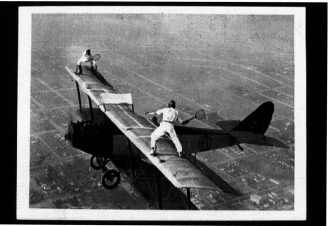
In a System Architecture lecture at MIT, Steve Imrich conveyed the essence of
emergence by showing the postcard in Figure 8 (Crawley, 2005). An airplane's wing was not designed to support a tennis match, and certainly not during flight. As stated earlier, a product system will be used in ways during its life cycle that the designers and
architects could not have foreseen.
Figure 8. Illustration of Emergent Use of a Product System
Emergence can bring forth both desirable and undesirable functions. The prior example was undesirable because a design team would be ill-prepared to generate an architecture that could exhibit robustness to a near infinite number of unknowns. However, in the course of developing a common engineering system, one takes advantage of the desirable
traits of emergence. The components are brought together to create a system with a new emergent process. Fan blades are assembled around a rotating shaft in a jet engine
system to aid in thrust production. The architect can zoom the desired emergent process to find its constituent sub-processes. Zooming is analogous to decomposition of function
(Crawley, 2005).
Emergence presents a challenge for engineers attempting to "build-in" robustness. Functions do not add linearly, so it is difficult to predict emergent functionality a priori (Crawley, 2005). With unknown-unknowns both internal and external to the system, how can we confidently architect and design robust systems? This brings us to the topic of section 3.6 - principles.
3.6 Principles and Heuristics
As one begins to architect a system, he will want to follow a process to guide his work and ensure the greatest expected value of utility for the stakeholders. There are four key categories of architecting methodologies that exist, and these are summarized in Table 2 (Rechtin and Maier, 2002; Lang, 1987; Rowe, 1987).
Table 2. Four Architecting Methodologies (Modified from Rechtin and Maier, 2002)
Normative Solution-based Building Codes, Communications Standards Rational Method-based Systems Analysis, Engineering
Participative Stakeholder-based Concurrent Engineering, Brainstorming Heuristic Lessons learned Keep it simple.
In this paper, the heuristic, or principle-based, approach is used to achieve robustness through systems architecting. Heuristics emerge as the lessons learned and the wisdom
from many years of experience, and are qualitative in nature. They are time-tested principles that guide the system architect towards a successful solution for a given
problem domain. Crawley (2005) defines principles as "the underlying and long enduring fundamentals that are always (or almost always) valid." As principles are qualitative in
nature, they cannot be "proven". However, some principles have lasted thousands of years, which gives us some level of confidence that they approach "truth".
One sample principle relevant to the topic of robustness is "robust functionality drives essential complexity" (Crawley, 2005). As mentioned in section 3.4, essential
complexity is the minimum complexity or information level necessary in a system architecture for the system to perform its intended operations. Robust functionality, the ability of the system to function in the face of variability, acts to increase the required complexity because additional functions are needed to compensate for the variability.
The proposed framework in this study is based on the heuristic approach, and principles are codified that help the architect achieve system robustness. Both the principles and framework are summarized in chapter six.
3.7 Summary
This chapter began with a description of system architecture, and it was followed with a discussion of the mapping of function to form through concept. I next defined
complexity and gave an overview of complex systems. After categorizing the different types of system complexity, the concept of emergence was explored. Now that we have established the essential background for system architecture and complex systems, we proceed to evaluate its interrelationship with robustness in chapter four.
4. Robustness and Reliability
"When a company's products are robust - highly functional, elegant in their design, fairly priced, and a pleasure to use - the corporation itself will be equally robust."
-Meyer and Lehnerd (1997)
4.1 Robustness
As the focus of this work lies in architecting robust complex systems, I now seek to provide the reader with a better understanding of what robustness entails, and how it may be imparted into a system. Many different definitions exist for robustness in the
literature, and in this chapter I establish the characteristics incorporated into the present study. The Santa Fe Institute compiled the following seventeen definitions from diverse domains such as robotics, software, ecosystems and other complex systems:
Table 3. Definitions of Robustness (Santa Fe, 2001)
Robustness is the persistence of specified system features in the face of a specified assembly of insults.
Robustness is the ability of a system to maintain function even with changes in internal structure or external environment.
Robustness is the ability of a system with a fixed structure to perform multiple functional tasks as needed in a changing environment.
Robustness is the degree to which a system or component can function correctly in the presence of invalid or conflicting inputs.
A model is robust if it is true under assumptions different from those used in construction of the model.
Robustness is the degree to which a system is insensitive to effects that are not considered in the design.
Robustness signifies insensitivity against small deviations in the assumptions. Robust methods of estimation are methods that work well not only under ideal conditions, but also under conditions representing a departure from an assumed distribution or model.
Robust statistical procedures are designed to reduce the sensitivity of the parameter estimates to failures in the assumption of the model.
Robustness is the ability of software to react appropriately to abnormal circumstances.
Robustness of an analytical procedure is a measure of its ability to remain
unaffected by small, but deliberate variations in method parameters, and provides
an indication of its reliability during normal usage.
Robustness is a design principle of natural, engineering, or social systems that have been designed or selected for stability.
The robustness of an initial step is determined by the fraction of acceptable options with which it is compatible out of total number of options.
A robust solution in an optimization problem is one that has the best performance under its worst case (max-min rule).
"..instead of a nominal system, we study a family of systems and we say that a certain property (e.g., performance or stability) is robustly satisfied if it is satisfied for all members of the family."
Robustness is a characteristic of systems with the ability to heal, repair, self-regulate, self-assemble, and/or self-replicate.
The robustness of language is a measure of the ability of human speakers to communicate despite incomplete information, ambiguity, and the constant element of surprise.
The definition of robustness adhered to in this paper is two-part. The first part is: Robustness is the ability of a system to perform its intended functions in the presence of environmental noise, internal noise, variations in production and variations resulting from time and use. This definition falls under the category of Type I robustness as illustrated in Table 4 (Chen, et al., 1996).
The second part covers variation in design variables or control factors, sometimes referred to as the adaptability of the system. This part is congruent with Type II
robustness (see Table 4). I do not, however, include Type III robustness in this research as the qualitative aspect of the architecture principle methodology is not readily amenable to quantification.
Table 4. Types of Robustness (Chen, et al., 1996)
• Jl ;•lY .- . .. I 9, - e
Type I Uncertainty in noise or environmental and other noise factors
Type II Uncertainty in design variables or control factors
Type III Uncertainty introduced by modelin methods
Type II robustness is important because complex systems can be long-lived, experiencing change to the system itself as well as changes to the system's context. Common
examples of long-standing systems include highway systems, satellite constellations and offshore oil platforms. Technologies evolve along their respective "S-curves", creating
new utility as well as new integration challenges for the system. Customers' use profile of the system may also change creating emergent processes and exposing the system to new environments. Type II robustness gives the system flexibility and adaptability so
that it can meet these environmental changes. Type II robustness is also important because it is the primary form of robustness that addresses the "ilities". The reader will note that the use of type II robustness here refers to control factor changes that happen before or after the product development process. This differs from Chen's intent to only be robust to control factor changes prior to release of the product.
In summary, the robustness framework and principles proposed in this thesis aim to improve both type I and II robustness.
4.2 Reliability
We extend our discussion of robustness into the area of reliability not only because it is a critical aspect of robust design, but also because reliability is what the market "sees". Reliability is commonly measured in industries, whereas robustness data can be obscure and difficult to obtain. In this respect, reliability enhances our ability to understand robustness changes in architecture. We now define reliability and discuss its relationship with robustness.
"Reliability is the proper functioning of the system under the full range of conditions experienced in the field." (Clausing and Frey, 2005)
"Reliability is the extent to which an experiment, test, or measuring procedure yields the same results on repeated trials." (Merriam-Webster, 2006)
We will adopt Clausing and Frey's definition for this research, along with their two requirements for reliability. These are:
1. Mistake avoidance 2. Robustness
The goal of the first requirement, mistake avoidance, is to eliminate errors that occur during the design process, during production or by the end-user. During the design process, decisions can be in error or based on the wrong data. In production, holes can be misdrilled and bolts can be installed backwards. The second requirement implies that robustness is necessary, but not sufficient, to achieve reliability. This is very useful as it enables us to exploit reliability data to discern the effects of architectural changes and innovations on robustness, as long as we also review the mistake avoidance component.
Recent jet engine models exhibit outstanding reliability, making them an excellent subject for further study. The GE90-115B turbofan engine, for example, has an engine departure reliability of 99.97% and has not experienced any in-flight shutdowns (GE, 2006). In the next chapter, we explore jet engine history more deeply to identify architecture, reliability and robustness trends.