Publisher’s version / Version de l'éditeur:
Journal of Thermal Spray Technology, 14, 1, 2005-03-01
READ THESE TERMS AND CONDITIONS CAREFULLY BEFORE USING THIS WEBSITE. https://nrc-publications.canada.ca/eng/copyright
Vous avez des questions? Nous pouvons vous aider. Pour communiquer directement avec un auteur, consultez la première page de la revue dans laquelle son article a été publié afin de trouver ses coordonnées. Si vous n’arrivez pas à les repérer, communiquez avec nous à [email protected].
Questions? Contact the NRC Publications Archive team at
[email protected]. If you wish to email the authors directly, please see the first page of the publication for their contact information.
NRC Publications Archive
Archives des publications du CNRC
This publication could be one of several versions: author’s original, accepted manuscript or the publisher’s version. / La version de cette publication peut être l’une des suivantes : la version prépublication de l’auteur, la version acceptée du manuscrit ou la version de l’éditeur.
For the publisher’s version, please access the DOI link below./ Pour consulter la version de l’éditeur, utilisez le lien DOI ci-dessous.
https://doi.org/10.1361/10599630522701
Access and use of this website and the material on it are subject to the Terms and Conditions set forth at
Elastic Modulus Measurements via Laser-Ultrasonic and Knoop
Indentation Techniques in Thermally Sprayed Coatings
Lima, R. S.; Krüger, S. E.; Lamouche, G.; Marple, B. R.
https://publications-cnrc.canada.ca/fra/droits
L’accès à ce site Web et l’utilisation de son contenu sont assujettis aux conditions présentées dans le site LISEZ CES CONDITIONS ATTENTIVEMENT AVANT D’UTILISER CE SITE WEB.
NRC Publications Record / Notice d'Archives des publications de CNRC:
https://nrc-publications.canada.ca/eng/view/object/?id=4d9586d5-71f2-4218-b094-99bcbdd663c4 https://publications-cnrc.canada.ca/fra/voir/objet/?id=4d9586d5-71f2-4218-b094-99bcbdd663c4
Elastic Modulus Measurements via
Laser-Ultrasonic and Knoop Indentation
Techniques in Thermally Sprayed Coatings
R.S. Lima, S.E. Kruger, G. Lamouche, and B.R. Marple
(Submitted September 15, 2003; in revised form December 1, 2004)
Nondestructive techniques for evaluating and characterizing coatings were extensively demanded by the thermal spray community; nonetheless, few results have been produced in practice due to difficulties in analyzing the complex structure of thermal spray coatings. Of particular interest is knowledge of the elastic modulus values and Poisson’s ratios, which are very important when seeking to understand and/or model the mechanical behavior or to develop life prediction models of thermal spray coatings used in various applica-tions (e.g., wear, fatigue, and high temperatures). In the current study, two techniques, laser-ultrasonics and Knoop indentation, were used to determine the elastic modulus of thermal spray coatings. Laser-ultrasonics is a noncontact and nondestructive evaluation method that uses lasers to generate and detect ultrasound. Ultrasonic velocities in a material are directly related to its elastic modulus value. The Knoop indentation technique, which has been widely used as a method for determining elastic modulus values, was used to compare and validate the measurements of the laser-ultrasonic technique. The determination of elastic modulus values via the Knoop indentation technique is based on the measurement of elastic recovery of the dimensions of the Knoop indentation impression. The approach used in the current study was to focus on evaluating the elastic modulus of very uniform, dense, and near-isotropic titania and WC-Co thermal spray coatings using these two techniques. Four different coatings were evaluated: two titania coatings produced by air plasma spray (APS) and high-velocity oxyfuel (HVOF) and two types of WC-Co coatings, conventional and multimodal (nanostructured and microsized particles), deposited by HVOF.
Keywords elastic modulus, Knoop indentation, laser-ultrasonics, titania, WC-Co
1. Introduction
1.1 Thermal Spray Microstructure and Coating Anisotropy
Thermal spray coatings are composed of splats or lamellae created by the rapid solidification of molten and/or semimolten feedstock particles, either on a substrate or on a layer of previ-ously deposited particles. These characteristics are unique and lead to the formation of complex microstructures. The pancake-shaped splat, ∼1 µm thick and ∼50 µm in diameter, is the basic structural unit of these coatings (Ref 1).
It has been shown that the porosity of plasma-sprayed ce-ramic coatings exhibits a bimodal distribution, with coarse pores in the size range 3 to 10 µm and fine ellipsoid pores having a width (minor axis) of 0.1 µm. The coarse porosity is due to in-complete filling of interstices between previously deposited
par-ticles, which is more likely if the impact particles are not com-pletely molten. The fine porosity in the microstructure of plasma-sprayed ceramic coatings is found in regions of perfect splat-splat contact separated by thin regions of no contact (Ref 2-5). These regions of poor contact are, physically, ellipsoid pores (interlamellar pores). The pores arise from gas entrapped beneath spreading liquid droplets during coating formation and, depending on factors such as particle viscosity, cooling rate, and velocity, the pore aspect ratio (i.e., the ratio of the major axis to the minor axis) may be close to 1 (for a near-spherical pore) or close to 10 (for a highly ellipsoid pore or crack) (Ref 6-8). It must be pointed out that differences in the terms used to describe a typical thermal spray microstructure, such as, pores and cracks, lie mostly in their aspect ratio (i.e., a high aspect ratio pore may be considered to be a crack) (Ref 8).
In addition to the weak horizontal splat boundaries that are characteristic of thermal spray coatings, thermal spray ceramic coatings may exhibit vertical microcracks within the splats (in-tralamellar cracks) initiating from the splat boundaries. These vertical microcracks are generated by quenching, a lack of plas-ticity of the ceramic material, and subsequent stress relaxation during the cool-down process (Ref 9).
The schematic of a typical thermal spray microstructure is shown in Fig. 1 (Ref 10). It is possible to observe the layered microstructure, the weak horizontal splat boundaries (interla-mellar pores), and the vertical microcracks (intrala(interla-mellar cracks) caused by stress relaxation, which lead to horizontally and ver-tically oriented pores and cracks. Therefore, the horizontal and vertical directions of the microstructure result in the known an-The original version of this article was published as part of the ASM
Proceedings, Thermal Spray 2003: Advancing the Science and Applying the Technology, International Thermal Spray Conference (Orlando, FL), 5-8 May, 2003, Basil R. Marple and Christian Moreau, Eds., ASM International, 2003.
R.S. Lima, S.E. Kruger, G. Lamouche, and B.R. Marple, National Research Council of Canada, 75 de Mortagne Boulevard, Boucherville, QC J4B 6Y4, Canada. Contact e-mail: [email protected].
JTTEE5 14:52-60
DOI: 10.1361/10599630522701 1059-9630/$19.00 © ASM International
Peer
isotropic behavior of the elastic modulus (E) and the hardness (H) of thermal spray coatings (Ref 8, 10).
1.2 Near-Isotropic Thermal Spray Coatings
In previous work (Ref 11-13), it was observed that high-velocity oxyfuel (HVOF)-sprayed and air plasma spray (APS)-sprayed titania coatings exhibited “bulk-like” or near-isotropic
E and H values. The value of E was determined via the Knoop
indentation technique (Ref 14) parallel to the deposition surface (cross section) and perpendicular to the deposition surface (in-plane), as shown in Fig. 1.
It has been suggested that a combination of three conditions contributes to producing coatings having near-isotropic me-chanical properties (e.g., E and H) in the cross section and top surface (Ref 11, 12): (a) microstructural and phase uniformity of the coating, (b) high density, and (c) narrow particle size range of the feedstock, resulting in a uniform particle heating.
1.3 Elastic Modulus Measurements: Knoop Indentation Technique
The elastic modulus is one of the most important mechanical properties. It enables the calculation of the elastic strain result-ing from the application of a given stress. Consequently, the knowledge of E will provide important information for under-standing the mechanical behavior of thermal spray coatings (e.g., crack propagation, toughness, and thermal shock behav-ior). Despite this importance, little information can be found in the thermal spray literature concerning the E values of thermal spray coatings. This lack of available data has its origin in the difficulties found in measuring the value of E for thermal spray coatings compared with those found in measuring the value of E of bulk materials. Also, the high variation of E values for coat-ings sprayed with different sets of parameters contributes to this lack of available data.
Marshall et al. (Ref 14) developed a method for determining the E of materials based on the measurement of the elastic re-covery of the in-surface dimensions of Knoop indentations. The ratio of the major (a) to minor (b) diagonals of the Knoop in-denter is 7.11. During unloading, the elastic recovery reduces
the length of the minor diagonal of the indentation impression (b⬘), while the length of the major diagonal of the indentation impression (a⬘) remains relatively unaffected. The difference between the known major-to-minor diagonal ratio (7.11) is com-pared with that of the indentation impression. The extent of re-covery depends on the elasticity index or hardness-to-modulus ratio. The formula for determining the elastic modulus (E, in Pa) is: E = 共−␣H兲
冉
b⬘ a⬘− b a冊
(Eq 1)where ␣ is a constant (0.45), H is Knoop hardness (in Pa), a⬘ and
b⬘ are the lengths of the major and minor diagonals of the inden-tation impression, and b/a is 1/7.11. It is important to point out that this equation was developed for isotropic materials. Conse-quently, the “rigorous real” value of E for anisotropic materials (such as the majority of the thermal spray coatings) may be dif-ferent from those obtained via the Knoop indentation technique. However, the concept of real E values for thermal spray coatings is beyond the scope of this work.
The advantage of the Knoop indentation technique is that the values of E and H can be obtained simultaneously, and a small specimen can be used for a large number of tests. The Knoop indentation test enables the E value of thermal spray deposits to be obtained in a simple fashion, at least when compared with other types of E determination methods, such as four-point bending. Nonetheless, the Knoop indentation method tends to exhibit a large scattering of data due to the nonhomogeneous nature of the thermal spray microstructures (Ref 10).
1.4 Elastic Modulus Measurements: Laser-Ultrasonics
The thermal spray community has widely demanded nonde-structive techniques for evaluating and analyzing coatings. One of the most promising techniques is laser-ultrasonics. Some ref-ereed studies are available in the literature (Ref 15-20).
Nondestructive ultrasonic techniques have been used to de-termine the elastic constants, such as E and the Poisson’s ratio (), of a variety of bulk materials (Ref 21, 22). However, it is diffi-cult to measure the elastic properties of thermal spray coatings by conventional ultrasonic techniques due to the porosity and extensive microcracking.
The laser-ultrasonics technique uses surface acoustic waves (SAWs) or Rayleigh waves to obtain information about a mate-rial. These SAWs or Rayleigh waves propagate along the sur-face of a material. The SAWs are generated by the instantaneous local thermal expansion and/or laser ablation. The concentration of the wave motion near the surface makes SAWs interesting for testing materials such as coatings or thin films (Ref 17, 19).
In the SAW technique, the surface waves are generated and detected at lengths much greater than the dimension of the film or coating thickness. Using this approach, the SAW result rep-resents the overall coating or material behavior (Ref 17). For a SAW, the depth of the wave motion is proportional to the wave-length. The SAWs with different frequencies (broadband) have different depths of penetration. Therefore, the coating thickness-Fig. 1 Schematic of a thermal spray microstructure taken from Ref 10
Peer
to-wavelength ratio (t/) is a parameter to be controlled; that is, the waves with shorter wavelengths will be localized at a small penetration depth of the material, and they must be chosen if coatings and thin films are to be analyzed (Ref 18, 19).
The wave motion (i.e., wave velocity) in a material will be influenced by its stiffness and density (Ref 23). Consequently, to measure the E (and ) of a material it is necessary to know its density and to measure the wave velocity in its medium. A laser pulse can generate many wave modes simultaneously. For laser generation and detection on the same surface but at different places, two types of ultrasonic waves, surface longitudinal (also known as skimming or p-waves) and Rayleigh waves, are of special interest, and their velocities are sufficient to determine E and . The two SAW velocities measured are the longitudinal velocity (VL) and the Rayleigh velocity (VR). In a longitudinal
wave, the particles of the medium move back and forth in the same direction as the wave, like the waves that travel down a coil spring when one end is pulled out and released. A Rayleigh wave has two components: (a) a longitudinal mode and (b) a trans-verse mode. In a transtrans-verse wave, the particles of the medium move back and forth perpendicular to the direction of the wave, like waves that travel down a stretched string when one end is shaken. VLand VRare measured independently due to the fact
that VLis approximately two times faster than VR.
The velocity measurement is carried out in the following way. The ultrasonic waves are generated by the local heating (local thermal expansion) created by pulses of a laser beam cused as a line on the coating surface. A detection laser is fo-cused on a point a few or several millimeters away from the position where the SAWs are generated. Once the SAW is de-tected, by knowing the time interval between wave generation and detection, and by knowing the exact distance between the pulsed laser focus point and the detection laser focus point in the material, the SAW velocity is easily determined by dividing dis-tance over time.
After the data are acquired, VRis combined with VLto obtain
the transverse velocity (VT). Having the density of the material
(), VL, and the VTobtained from VR, the equations linking the
elastic characteristics with the wave velocities for isotropic ma-terials are (Ref 24):
E = V2T
共
3V2 L− 4V 2 T兲
共
V2 L− V 2 T兲
(Eq 2) v =共
V2 L− 2V 2 T兲
2共
V2 L− V 2 T兲
(Eq 3)As previously mentioned, these equations are applied when determining the elastic constants of isotropic materials. For an-isotropic materials, the determination of the elastic constants be-comes more complex (Ref 25, 26). The wave velocities have to be determined for each anisotropic direction, and the equations applied to measure the elastic constants become more compli-cated.
1.5 A New Approach and Objectives
Despite the publication of various refereed studies in the coatings literature on laser-ultrasonics and E measurements (Ref
15-19), this method is not very well known and is little used by the thermal spray community. One of the reasons for this is, as already discussed, the highly anisotropic and inhomogeneous structure of these coatings, consisting of intersplat pores and cracks (Ref 2-10). These features may attenuate and scatter the ultrasonic waves, increasing the background noise and making it difficult to interpret the ultrasonic signals and obtain reliable data.
To test and validate the laser-ultrasonics technique for mea-suring E values of thermal spray coatings, it is necessary to com-pare the results to those determined using other approaches. The Knoop indentation technique developed by Marshall et al. (Ref 14) to measure E values has been used by several authors to analyze bulk materials and coatings (Ref 10, 27-32). This is a destructive technique based on a principle that is very different from that of laser-ultrasonics. Consequently, the agreement of the E values of thermal spray coatings measured using these two independent techniques would demonstrate the usefulness of laser-ultrasonics and would increase the level of acceptance of this approach in the thermal spray community.
As an initial step, to help limit the problems caused by the complex structure of thermal spray coatings a new approach was attempted. Near-isotropic HVOF-sprayed and APS-sprayed titania coatings (Ref 11-13) were analyzed via laser-ultrasonics. It is thought that by analyzing homogeneous coatings (from a thermal spray perspective) Eq 2 and 3, which were applied for the determination of the elastic constants of isotropic materials, could be used to determine the E and of these near-isotropic titania coatings.
To test this hypothesis, the E values obtained via the nonde-structive laser-ultrasonics technique are compared with those obtained via the Knoop indentation technique (Ref 14), which has already been stated. In addition to this perspective, the use of relatively uniform coatings may “facilitate” the process of inter-pretation of the ultrasonic signals, serving as a basis for the fur-ther investigation of more complex coatings.
In the second phase of this study, nanostructured and conven-tional WC-12wt.%Co HVOF-sprayed coatings were analyzed by the two techniques to determine whether these two-phase ma-terials could be correctly characterized using laser-ultrasonics.
It is important to point out that the E values of thermal spray coatings are not widely available as hardness values. Also, there is one important thing to add. Due to the complexity of thermal spray coatings, each coating has its distinct E value. It is very different from regular bulk materials, which exhibit more stable values of E.
2. Experimental Procedure
2.1 APS-Sprayed and HVOF-Sprayed Titania
A fused and crushed titania (TiO2) feedstock (Flomaster
22.8(99)F4, F.J. Brodmann & Co., Harvey, LA) with a nominal particle size range from 5 to 20 µm was sprayed using an HVOF torch (DJ 2700-hybrid, Sulzer-Metco, Westbury, NY) and an APS torch (F4, Sulzer-Metco). The spray parameters are listed in Tables 1 and 2.
The spray parameters for the HVOF-sprayed titania (Table 1) were previously developed and optimized (Ref 11, 12), consid-ering the set that exhibited the highest average particle
tempera-Peer
ture, without causing damage to the spray torch due to excessive heat of the flame. The spray parameters for APS titania (Table 2) were developed (Ref 13) to produce dense and uniform coatings. The coating thicknesses for the HVOF and APS titania were ∼550 and ∼400 µm, respectively.
2.2 WC-12wt.%Co Coatings
A conventional and a multimodal WC-Co feedstock were sprayed using an HVOF torch (JP5000, Praxair-Tafa, Concord, NH). The conventional agglomerated and sintered WC-Co feed-stock (1342VM, Praxair, Indianapolis, IN) had a nominal par-ticle size distribution from 15 to 45 µm. Each single multimodal feedstock particle (Nanomyte WC-Co, Nanopowder Enter-prises, Piscataway, NJ) consisted of a combination of 50% of micron-sized particles and 50% of nanometer-sized particles of WC. The multimodal particles were produced via spray drying. The overall nominal particle size distribution varied from 5 to 40 µm. The spray parameters are listed in Table 3. The coating thickness for the conventional and multimodal WC-Co was ∼360 µm.
2.3 Substrate and Coating Temperature
The coatings were deposited on low-carbon steel substrates that had been grit-blasted to roughen the surface before spray-ing. During the spraying process, a cooling system consisting of air jets was applied to reduce coating temperature. The coating temperature was monitored during spraying using a pyrometer. The maximum coating temperatures during the process were ∼325 and ∼170 °C, respectively, for the HVOF and APS titania. For the two types of WC-Co, the maximum coating temperature during the process was ∼220 °C.
2.4 Microstructure and Coating Porosity
Samples of both the cross section and the top surface of the coatings were vacuum-impregnated and polished for study using a scanning electron microscope (SEM). Coating porosity was evaluated on the cross section of the coatings using SEM and image analysis. A total of 5 (titania) and 10 (WC-Co) SEM pic-tures was analyzed for porosity measurements.
2.5 Elastic Modulus Measurements via Knoop Indentation Technique
The elastic modulus values determined via the Knoop inden-tation technique (Ref 14) were measured on the cross section and top surface (in-plane) of the coatings under a load of 1000 g and an indentation time of 15 s. For the cross sections, the indenta-tions were applied near the centerline of the coating thickness, with the major diagonal perpendicular to the substrate plane. A total of 20 measurements was performed for each indentation series.
2.6 Elastic Modulus Measurements via Laser-Ultrasonics
The SAWs were generated by a neodymium-doped yttrium-aluminum garnet (Nd-YAG) laser (third harmonic 355 nm) pulse (8 ns) focused as a line (10 × 0.2 mm) on the as-sprayed coating surface. No surface preparation, such as grinding or pol-ishing, was carried out. For this technique, the propagating waves were detected at different distances by a point-focused long laser pulse (60 µs) from a detection Nd-YAG laser in its fundamental wavelength (1064 nm). The movement of the coat-ing surface due to the SAW changes the frequency of the re-flected detection laser light via the Doppler effect. These fre-quency changes are converted into an electrical signal by a Fabry-Perot interferometer. The signals are digitized and re-corded for further processing. A total of 13 to 16 measurements at different propagation distances were performed for each se-ries of laser-ultrasonics analysis.
3. Results and Discussion
3.1 Microstructure, Density, and Porosity
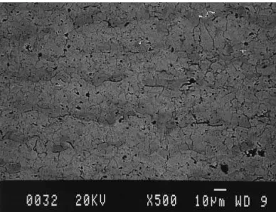
Figures 2 and 3 show the microstructure of the HVOF-sprayed and APS-HVOF-sprayed titania coatings, respectively. The coatings are dense and are homogeneous throughout the struc-ture. The porosity is <1%. It can be noticed that, despite being
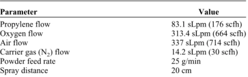
Table 1 Spray parameters for the HVOF-sprayed titania
(DJ2700-hybrid)
Parameter Value
Propylene flow 83.1 sLpm (176 scfh)
Oxygen flow 313.4 sLpm (664 scfh)
Air flow 337 sLpm (714 scfh)
Carrier gas (N2) flow 14.2 sLpm (30 scfh)
Powder feed rate 25 g/min
Spray distance 20 cm
Note: sLpm, standard liters per minute; scfh, standard cubic feet per hour
Table 2 Spray parameters for the APS-sprayed titania (F4)
Parameter Value
Primary gas (Ar) flow 40 sLpm
Secondary gas (H2) flow 14.8 sLpm
Current 600 A
Voltage 69.6 V
Power 41.8 kW
Carrier gas (Ar) flow 3 sLpm
Powder feed rate 20 g/min
Powder injector size 1.8 mm (diameter)
Powder injector angle 90°
Powder injector distance 6 mm
Spray distance 10 cm
Note: sLpm, standard liters per minute
Table 3 Spray parameters for the conventional and
multimodal WC-12wt.%Co
Parameter Value
Kerosene flow 20.4 sLpm (5.4 gph)
Oxygen flow 850 sLpm (1800 scfh)
Carrier gas (N2) flow 11.8 sLpm (25 scfh)
Powder feed rate 75 g/min
Spray distance Tafa 1342VM: 38 cm
Nanomyte: 20 cm Note: gph, gallons per minute; scfh, standard cubic feet per hour
Peer
very dense and uniform, the two titania microstructures have significant differences. It must be remembered that these coat-ings were made from the same feedstock material. The HVOF-sprayed titania exhibits cracks and/or pores, mainly parallel to the deposition surface. The APS-sprayed titania distinctively ex-hibits cracks and/or pores parallel and perpendicular to the de-position surface.
Figures 4 and 5 show the typical microstructures of the con-ventional and multimodal WC-Co coatings. It is noticed that both microstructures are dense. The porosity for the two types of coatings is <1%. The conventional and multimodal natures of these coatings are easily distinguished. The conventional WC-Co (Fig. 4) has coarser WC particles in the micro-structure when compared with that of the multimodal WC-Co (Fig. 5). The lamellar and/or vertical cracks found in the ther-mal-sprayed ceramic coatings are not observed for the two-cermet coatings. The lamellar structure is not easily distinguish-able due to the high particle-impact velocity exhibited by the
HVOF systems, which can reach values on the order of 800 m/s (Ref 33). The presence of the metallic phase (Co) enhances the ductility of the WC-Co cermet, and consequently it is thought that quenching stresses can be relaxed via plastic deformation (Ref 9).
The coating densities were indirectly determined based on the composition of the coatings. X-ray diffraction analysis indi-cated that the APS-sprayed and HVOF-sprayed titania contained stoichiometric TiO2rutile as the major phase (Ref 12, 13). The
theoretical density of the rutile is 4.25 g/cm3(Ref 34). Due to the
low porosity values of both coatings (<1%), their densities were taken as the theoretical value of 4.25 g/cm3.
The same approach was taken for the two WC-12wt.%Co coatings. The density values are 15.7 and 8.8 g/cm3,
respec-tively, for the WC and Co (Ref 34). As the porosity levels of the two WC-Co coatings were <1%, it was considered that the coat-ing densities were both 13.69 g/cm3, as calculated based on the
proportion of the two phases present in the feedstock. Fig. 2 Microstructure (cross section) of the HVOF-sprayed titania
Fig. 3 Microstructure (cross section) of the APS-sprayed titania
Fig. 4 Microstructure (cross section) of the HVOF-sprayed conven-tional WC-Co
Fig. 5 Microstructure (cross section) of the HVOF-sprayed multimo-dal WC-Co
Peer
3.2 Elastic Modulus
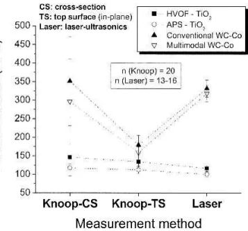
The E values measured via Knoop indentation and laser-ultrasonic techniques for the titania and WC-Co coatings are plotted in Fig. 6. The results of the SAW velocity (VLand VR)
measurements are listed in Table 4. It is noticed that the E values measured via the Knoop indentation technique are near-isotropic for the titania coatings. It is important to point out that these coatings were previously developed to have very dense and homogeneous microstructures (Ref 12, 13). When compar-ing the E values of titania obtained via Knoop indentation to those obtained via laser-ultrasonics, a good correlation between the results obtained using the two techniques is observed.
As previously stated in this work, Eq 2 and 3 are applied to determine E and values in isotropic materials. The good agree-ment between these two distinctive (destructive and nondestruc-tive) techniques used in the current study emphasizes the idea that these coatings exhibit a near-isotropic behavior with respect to E. The WC-Co coatings exhibited the traditional behavior of thermal spray coatings; that is, the E values measured via the Knoop technique on the cross section and top surface (in-plane) were different (Fig. 6) (Ref 10, 29). However, there is a good agreement between the E values measured via the Knoop tech-nique on the cross section with those measured via laser-ultrasonics (Fig. 6).
It is important to point out that it would be more difficult to compare the E values obtained via laser-ultrasonics with those obtained via other measurement methods, such as four-point bending. Laser-ultrasonics and the Knoop indentation technique measure the E values in localized points of the microstructure, whereas, four-point bending measures E throughout the coating microstructure. During four-point bending, some pores are healed or compressed, therefore changing the E value of the coating.
To have a better understanding of the near-isotropic behavior of the titania and the anisotropic behavior of the WC-Co coat-ings, micrographs of the Knoop indentation impressions on the cross section and top surface (in-plane) of these coatings were
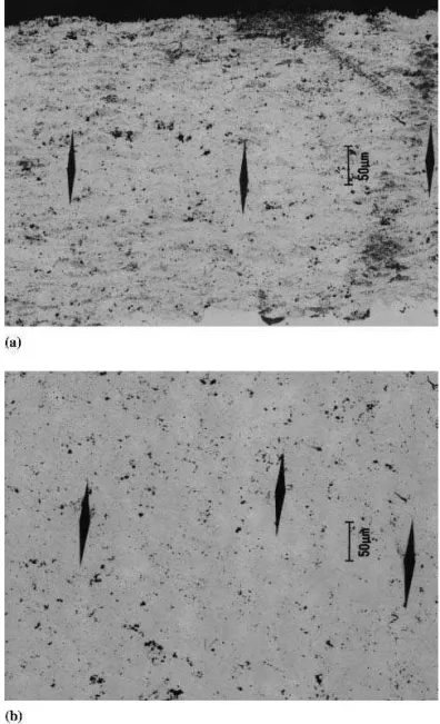
compared. Figure 7 shows the Knoop indentation impressions (cross section and top surface) of the APS-sprayed titania.
For this coating, the dimensions of the indentation impres-sions (major a⬘ and minor b⬘ diagonals) are very similar on the cross section and top surface. Therefore, the elastic-plastic be-havior or the elastic constants of this coating should be near-isotropic. The same behavior was observed in the micrographs (not shown) of the HVOF-sprayed titania.
Figure 8 shows the Knoop indentation impressions on the cross section and top surface of the multimodal WC-Co coating. The major and minor diagonals of these impressions have dif-ferent dimensions, on the cross section and top surfaces. It is important to recall that all micrographs were taken at the same magnification. For the multimodal WC-Co coating, the major and minor diagonals of the indentation impression are larger on the top surface than they are on the cross section. The same be-havior was observed for the conventional WC-Co coating (mi-crographs not shown). Consequently, the elastic-plastic behav-ior or the elastic constants of these WC-Co coatings are different in the cross section and top surface (in-plane).
3.3 Poisson’s Ratio
The values for of the titania and WC-Co coatings are shown in Fig. 9. These values were calculated using Eq 3. The two WC-Co coatings exhibited very similar values. The two titania coatings had similar E values (Fig. 6) but exhibited quite differ-ent values. The elastic constants of materials are E, shear modulus (G), and the bulk modulus (K). The relationship be-tween the elastic constants for an isotropic material is (Ref 35):
E = 2G共1 + v兲= 3K共1 − 2v兲 (Eq 4)
Consequently, although the two titania coatings have similar values of E, they will exhibit different stress-strain behaviors when shear or compressive stresses are applied. Thus, depend-ing on the conditions in which the coatdepend-ing is operatdepend-ing, one of these titania coatings may be a more suitable candidate for the application. This type of information has significant implica-tions for coatings design: knowledge of the E and values is important for engineering a coating for a specific application or for understanding the mechanism of failure of a coating under stress.
3.4 Near-Isotropic and Anisotropic Behavior
Near-isotropic behavior was observed only for the titania coatings. As already discussed, this near-isotropic character Fig. 6 Elastic modulus values for the titania and WC-Co coatings
measured via the Knoop indentation and laser-ultrasonic techniques
Table 4 Longitudinal (VL) and Rayleigh (VR) velocity
measurements
Coating and velocity type Velocity, m/s
TiO2—HVOF—VR 3180 ± 506 TiO2—HVOF—VL 5729 ± 262 TiO2—APS—VL 5911 ± 438 TiO2—APS—VR 2834 ± 96 WC-Co (multimodal)—VL 5766 ± 268 WC-Co (multimodal)—VR 2687 ± 96 WC-Co (conventional)—VL 5778 ± 199 WC-Co (conventional)—VR 2754 ± 102
Peer
Reviewed
arises from three main features (Ref 11, 12): microstructural and phase uniformity of the coating, high density, and narrow par-ticle size range of the feedstock, resulting in a uniform parpar-ticle heating.
On the other hand, the WC-Co coatings exhibit the traditional anisotropic behavior of thermal spray coatings (Fig. 6, 8). For these coatings, the results of the laser-ultrasonics for the deter-mination of E agree well with those of the Knoop indentation measured on the cross section (Fig. 6). As previously discussed in the text, longitudinal waves propagate like the waves that travel down a coil spring when one end is pulled out and re-leased. Therefore, the longitudinal waves generate cycles of compression and tension parallel to the coating surface (i.e., throughout the cross section). Consequently, the longitudinal waves, which propagate through the cross section, strongly con-tribute to the results. This may be the reason why E values mea-sured via Knoop indentation on the cross section showed a better agreement with those measured via laser-ultrasonics for the
WC-Co coatings. This is a supposition, and further research will have to be carried out to prove this hypothesis.
4. Conclusions
• The E values and the indentation impression dimensions of APS-sprayed and HVOF-sprayed titania coatings were found to be very similar in the cross-section and top-surface (in-plane) directions. These E values exhibited a good agreement with those measured via laser-ultrasonics. • The good correlation of the Knoop indentation and
laser-ultrasonic results for the titania coatings reinforced the idea that these coatings are near-isotropic with respect to E. • The E values and the indentation impression dimensions of
the WC-Co coatings were different in the cross-section and top-surface (in-plane) directions. The E values measured on Fig. 7 (a) Knoop indentation impressions. (a) On the cross section of
the ASP-sprayed coating. (b) On the top surface (in-plane) of the HVOF-sprayed titania coating
Fig. 8 Knoop indentation impressions. (a) On the cross section of the multimodal WC-Co coating. (b) On the top surface (in-plane) of the multimodal WC-Co coatings
Peer
the cross section agreed well with those measured via laser-ultrasonics.
• The titania coatings exhibited significantly different val-ues, although they had very similar E values. This charac-teristic shows the importance of knowing the E and values of thermal spray coatings to engineer them for specific ap-plications.
• No significant differences were found in the values of the conventional and multimodal WC-Co coatings.
• The near-isotropic behavior of the titania coatings is due to the high density and microstructural homogeneity exhibited by the two titania systems.
• The anisotropic behavior of the WC-Co coatings is thought to have its origin in the inhomogeneous distribution of the WC phase in the Co matrix, which may come from the plas-tic deformation of the Co metallic phase during impact and the spreading of the WC-Co particles.
• E values measured via the Knoop indentation and
laser-ultrasonic techniques, in general, were in good agreement. Consequently, the potential value of this nondestructive evaluation technique (laser-ultrasonics) for application in evaluating various types of thermal spray coatings should be explored further.
References
1. L. Pawlowski, The Science and Engineering of Thermal Spray Coat-ings, John Wiley & Sons, Chichester, West Sussex, England, 1995 2. R. McPherson, A Review of Microstructure and Properties of Plasma
Sprayed Ceramic Coatings, Surf. Coat. Technol., Vol 39/40, 1989, p 173-181
3. R. McPherson and B. V. Shaffer, Interlamellar Contact Within Plasma-Sprayed Coatings, Thin Solid Films, Vol 97, 1982, p 201-204 4. R. McPherson, The Relationship Between the Mechanism of
Forma-tion, Microstructure and Properties of Plasma-Sprayed Coatings, Thin Solid Films, Vol 83, 1981, p 297-310
5. R. McPherson, A Model for the Thermal Conductivity of Plasma-Sprayed Ceramic Coatings, Thin Solid Films, Vol 112, 1984, p 89-95 6. J. Ilavsky, A.J. Allen, G.G. Long, and S. Krueger, Influence of Spray
Angle on the Pore and Crack Microstructure of Plasma-Sprayed Depos-its, J. Am. Ceram. Soc., Vol 80 (No. 3), 1997, p 733-742
7. S.H. Leigh and C.C. Berndt, Quantitative Evaluation of Void Distribu-tions Within a Plasma-Sprayed Ceramic, J. Am. Ceram. Soc., Vol 82 (No. 1), 1999, p 17-21
8. T. Nakamura, G. Qian, and C.C. Berndt, Effects of Pores on Mechanical Properties of Plasma-Sprayed Ceramic Coatings, J. Am. Ceram. Soc., Vol 83 (No. 3), 2000, p 578-584
9. S. Kuroda and T.W. Clyne, The Quenching Stress in Thermally Sprayed Coatings, Thin Solid Films, Vol 200, 1991, p 49-66
10. S.H. Leigh, C.K. Lin, and C.C. Berndt, Elastic Response of Thermal Spray Deposits Under Indentation Tests, J. Am. Ceram. Soc., Vol 80 (No. 8), 1997, p 2093-2099
11. R.S. Lima and B.R. Marple, High Weibull Modulus HVOF Titania Coatings, J. Thermal Spray Technol., Vol 12 (No. 2), 2003, p 240-249 12. R.S. Lima and B.R. Marple, Optimized High Velocity Oxy-Fuel Titania Coatings, J. Thermal Spray Technol., Vol 12 (No. 3), 2003, p 360-369 13. R.S. Lima and B.R. Marple, Comparative Study of HVOF and APS Titania Coatings, Proceedings from the First International Surface En-gineering Congress and the 13th IFHTSE Congress, N. Dahotre, J.O. Iroh, D. Herring, S. Midea, and H. Kopech, Ed., ASM International, 2003, p 515-519
14. D.B. Marshall, T. Noma, and A.G. Evans, A Simple Method for Deter-mining Elastic-Modulus-to-Hardness Ratio using Knoop Indentation Measurements, J. Am. Ceram. Soc., Vol 65 (No. 10), 1982, p C-175-176 15. S. Parthasarathi, B.R. Tittmann, K. Sampath, and E.J. Onesto, Ultra-sonic Characterization of Elastic Anisotropy in Plasma-Sprayed Alu-mina Coatings, J. Thermal Spray Technol., Vol 4 (No. 4), 1995, p 367-373
16. G. Rosa, P. Psyllaki, R. Oltra, T. Montesin, C. Coddet, and S. Costil, Laser Ultrasonic Testing for Estimation of Adhesion of Al2O3Plasma
Sprayed Coatings, Surf. Eng., Vol 17 (No. 4), 2001, p 332-338 17. X.Q. Ma, Y. Mizutani, and M. Takemoto, Laser-Induced Surface
Acoustic Waves for Evaluation of Elastic Stiffness of Plasma Sprayed Materials, J. Mater. Sci., Vol 36, 2001, p 5633-5641
18. D. Schneider, T. Schwarz, H.P. Buchkremer, and D. Stover, Non-Destructive Characterization of Plasma-Sprayed ZrO2Coatings, Thin
Solid Films, Vol 224, 1993, p 177-183
19. D. Schneider and B. Schultrich, Elastic Modulus: A Suitable Quantity for Characterization of Thin Films, Surf. Coat. Technol., Vol 98, 1998, p 962-970
20. M. Viens, D. Drolet, A. Blouin, J. P. Monchalin, C. Moreau, Nonde-structive Characterization of Plasma Sprayed Coatings by Laser Ultra-sonics, Thermal Spray: Practical Solutions for Engineering Problems, C.C. Berndt, Ed., Oct 7-11, 1996 (Cincinnati, OH), ASM International, 1996, p 947-951
21. D.N. Boccaccini and A.R. Boccaccini, Dependence of Ultrasonic Ve-locity on Porosity and Pore Shape in Sintered Materials, J. Nondestruct. Eval., Vol 16 (No. 4), 1997, p 187-192
22. M. Asmani, C. Kermel, A. Leriche, and M. Ourak, Influence of Porosity on Young’s Modulus and Poisson’s Ratio in Alumina Ceramics, J. Eur. Ceram. Soc., Vol 21, 2001, p 1081-1086
23. M.E. Browne, Physics for Engineering and Science, McGraw-Hill, 1999
24. E. Schreiber, O.L. Anderson, and N. Soga, Elastic Constants and Their Measurement, McGraw-Hill, 1973
25. Y.M. Liu, T.E. Mitchell, and H.N.G. Wadley, Anitropic Damage Evo-lution in Unidirectional Fiber Reinforced Ceramics, Acta Mater., Vol 45 (No. 10), 1997, p 3981-3992
26. Q.B. Zhou, S.Y. Zhang, and Y.K. Lu, Acoustic Anisotropy of Piezo-electric PbB4O7 Crystals Studied by Laser Ultrasonics, Mater. Sci. Eng., B, Vol 83, 2001, p 249-253
27. M.A. Camerucci, G. Urretavizcaya, and A.L. Cavalieri, Mechanical Be-havior of Cordierite and Cordierite-Mullite Materials Evaluated by In-dentation Techniques, J. Eur. Ceram. Soc., Vol 21, 2001, p 1195-1204 28. J. Gong, Z. Zhao, Y. Yang, Z. Guan, and H. Miao, Statistical Variability in the Indentation Toughness of TiCN Particle Reinforced Al2O3
Com-posite, Mater. Lett., Vol 49, 2001, p 357-360
29. H.J. Kim and Y.G. Kweon, Elastic Modulus of Plasma-Sprayed
Coat-Fig. 9 Poisson’s ratio for the titania and the conventional (C) and mul-timodal (M) WC-Co coatings
Peer
ings Determined by Indentation and Bend Tests, Thin Solid Films, Vol 342, 1999, p 201-206
30. J. Li and C. Ding, Determining Microhardness and Elastic Modulus of Plasma-Sprayed Cr3C2-NiCr Coatings Using Knoop Indentation Test-ing, Surf. Coat. Technol., Vol 135, 2001, p 229-237
31. D. Zhu and R.A. Miller, Thermal Conductivity and Elastic Modulus Evolution of Thermal Barrier Coatings Under High Heat Flux Condi-tions, J. Thermal Spray Technol., Vol 9 (No. 2), 2000, p 175-180 32. S.W.K. Kweh, K.A. Khor, and P. Cheang, Plasma-Sprayed
Hydroxy-apatite (HA) Coatings with Flame-Spheroidized Feedstock:
Micro-structure and Mechanical Properties, Biomaterials, Vol 21, 2000, p 1223-1234
33. B.R. Marple, J. Voyer, J.F. Bisson, and C. Moreau, Thermal Spraying of Nanostructured Cermet Coatings, J. Mater. Process. Technol., Vol 117, 2001, p 418-423
34. MatWeb-Material Property Data Home Page, www.matweb.com (ac-cessed Sept 24, 2002)
35. J.C. Anderson, K.D. Leaver, R.D. Rawlings, and J.M. Alexander, Ma-terials Science, 4th ed., Chapman & Hall, 1991