Publisher’s version / Version de l'éditeur:
Vous avez des questions? Nous pouvons vous aider. Pour communiquer directement avec un auteur, consultez la première page de la revue dans laquelle son article a été publié afin de trouver ses coordonnées. Si vous n’arrivez pas à les repérer, communiquez avec nous à [email protected].
Questions? Contact the NRC Publications Archive team at
[email protected]. If you wish to email the authors directly, please see the first page of the publication for their contact information.
https://publications-cnrc.canada.ca/fra/droits
L’accès à ce site Web et l’utilisation de son contenu sont assujettis aux conditions présentées dans le site LISEZ CES CONDITIONS ATTENTIVEMENT AVANT D’UTILISER CE SITE WEB.
Contractor Report (National Research Council of Canada. Institute for Ocean Technology); no. CR-2005-01, 2005
READ THESE TERMS AND CONDITIONS CAREFULLY BEFORE USING THIS WEBSITE. https://nrc-publications.canada.ca/eng/copyright
NRC Publications Archive Record / Notice des Archives des publications du CNRC :
https://nrc-publications.canada.ca/eng/view/object/?id=d67684ec-72a7-48b5-a600-99a1a569f2bd https://publications-cnrc.canada.ca/fra/voir/objet/?id=d67684ec-72a7-48b5-a600-99a1a569f2bd
For the publisher’s version, please access the DOI link below./ Pour consulter la version de l’éditeur, utilisez le lien DOI ci-dessous.
https://doi.org/10.4224/8894882
Access and use of this website and the material on it are subject to the Terms and Conditions set forth at Hardware selection recommendations for the NRC Segment Wave Generator Control System
Contractor Report
CR-2005-01
Hardware Selection Recommendations for the NRC
Segment Wave Generator Control System
P. Laurich, BA Technologies
March 2005
CR-2005-01 March 2005
REPORT SECURITY CLASSIFICATION
Unclassified
DISTRIBUTION
Unlimited
TITLE
HARDWARE SELECTION RECOMMENDATIONS FOR THE NRC SEGMENT WAVE GENERATOR CONTROL SYSTEM Final Report
AUTHOR(S)
Peter Laurich
CORPORATE AUTHOR(S)/PERFORMING AGENCY(S)
BA Technologies
PUBLICATION
SPONSORING AGENCY(S)
Institute for Ocean Technology, National Research Council, St. John’s, NL
IOT PROJECT NUMBER
42_2076_10
NRC FILE NUMBER
KEY WORDS
wave generator control system
PAGES i, 15, App. A FIGS. TABLES 15 SUMMARY
In early 1991, NRC developed the second generation of its digital control system for segmented wave generators. The design used off-the-shelf technology – both hardware and software – to the extent possible at the time. The system was based on the
original VME standard (VMEbus) and the pSOS real-time operating system.
The system has performed well but all of the hardware has now been discontinued. The operating system software is in maintenance-only mode and the software development environment is no longer functional or supported. It has become imperative that the control system be upgraded to use current technology – both hardware and software. This report deals with the selection of new hardware for the control system. Hardware must be selected with an awareness of the options for the new operating system. The selection of the operating system will, however, be completed in a follow-on phase.
ADDRESS National Research Council
Institute for Ocean Technology Arctic Avenue, P. O. Box 12093 St. John's, NL A1B 3T5
Technology océaniques
HARDWARE SELECTION RECOMMENDATIONS
FOR THE NRC SEGMENT WAVE GENERATOR
CONTROL SYSTEM
Final Report CR-2005-01 Peter Laurich BA Technologies March 2005Hardware Selection Recommendations
For the
NRC Segment Wave Generator Control System
Version: 1.00 Status: Final March 29, 2004
Prepared by BA Technologies
Hardware Selection v 1.00.doc Status: Draft i
Table of Contents
Table of Contents ... i
1. Introduction ...1
2. Current System Configuration ...2
2.1. Hardware ...2
2.2. Operating System Software...3
3. Backplane Standard Analysis...4
4. VME bus Options...5
4.1. CPU Boards...5 4.1.1. Ranking Process ...5 4.1.2. Top Three ...7 4.2. Digital I/O ...8 4.3. Analog I/O...8 4.3.1. Carrier Packs ...8 4.3.2. Analog Input...8 4.3.3. Analog Output...8 4.4. VME Recommendation...9 5. cPCI Options ...10 5.1. CPU Boards...10 5.1.1. Ranking Process ...10 5.2. Digital I/O ...11 5.3. Analog I/O...11 5.3.1. Carrier Packs ...11 5.3.2. Analog Input...11 5.3.3. Analog Output...11 5.4. 6U cPCI Recommendation...11 5.4.1. 3U cPCI Option...12
5.5. Custom Digital Board ...13
6. Final Recommendations...14
6.1. Points to Note...15
Hardware Selection v 1.00.doc Status: Draft 1
1. Introduction
In early 1991, NRC developed the second generation of its digital control system for segmented wave generators. The design used off-the-shelf technology – both hardware and software – to the extent possible at the time. The system was based on the original VME standard (VMEbus) and the pSOS real-time operating system.
The system has performed well but all of the hardware has now been discontinued. The operating system software is in maintenance-only mode and the software development environment is no longer functional or supported. It has become imperative that the control system be upgraded to use current technology – both hardware and software.
This report deals with the selection of new hardware for the control system. Hardware must be selected with an awareness of the options for the new operating system. The selection of the operating system will, however, be completed in a follow-on phase.
The strategy used in developing the hardware recommendations were: • Extract the specifications from the existing control system
• Examine recent trends in backplane technology, hardware technology and operating system technology
• Develop a short list of candidate hardware choices • Develop system costs
Hardware Selection v 1.00.doc Status: Final 2
2. Current System Configuration
2.1. Hardware
The current NRC segmented wave generator control system includes the following board-level products per MCU:
• Force processor board: CPU-40 B/16 • Acromag digital I/O board: AVME 9481
• One Acromag analog input board for every type of feedback device used by the control system: AVME 9330
• One Acromag analog output board for every 8 segments controlled by the MCU (the system supports a maximum of 32 segments per MCU): AVME 9210
• Custom digital board (either NRC IMD or Davis Engineering) CPU Board (specs reflect the current board):
• 68040 CPU running at 25 MHz with a 4 Kbyte instruction cache and a 4 Kbyte data cache – the floating point component is required
• DMA controller
• 4 serial I/O channels, 2 of which are in use. One is used for terminal I/O and the second is used for synch signals (drive signal start and 100 Hz clock)
• 10 Mbps Ethernet port with 64 Kbyte data buffer • Memory:
128 Kbyte SRAM with battery backup 128 Kbyte FLASH
16 Mbyte DRAM
1 boot EPROM for local booting
2 boot EPROMs for application booting Digital I/O Board:
• 6 digital output signals • Sink up to 100 mA Analog Input Boards:
• 32 single-ended channels
• High-level voltage input (+/- 10V range) • 16-bit resolution
• Sampling rate of up to 30kHz
• External connections via a rear connector (P2) Analog Output Boards
• 8 output channels per board
• High-level voltage output (+/- 5V range) • 12-bit resolution
• Settling time less than 6 microseconds
Hardware Selection v 1.00.doc Status: Draft 3 System Chassis:
• Sufficient slots for a controller including: 1 processor board
Up to 3, 32-channel analog input boards Up to 4, 8-channel analog output boards
1 digital I/O board for up to 6 signals (handles up to 64 signals of I/O) 1 custom digital board (board takes only power from the backplane)
2.2. Operating System Software
The control system software uses the pSOS operating system. The rights to the operating system have been purchased by Wind River, the developer of VxWorks. Wind River has maintained support for pSOS but there is no new investment in the software – pSOS is no longer a suitable candidate for real-time operating systems for new designs.
The operating system components used in the segmented wave generator control software are shown in the table below. The functionality provided by each of these components would be required in any replacement RTOS being considered
Component Description Calls Description
ev_receive Wait for an event
ev_send Send an event
k_fatal Signal a fatal error
q_create Create a message queue
q_delete Delete a message queue
q_ident Identify a message queue
q_receive Wait for a message at a queue
q_send Send a message to a queue
q_urgent Put a message at the head of a queue
t_create Create a task
t_ident Identify a task
t_setpri Set a task priority
t_start Start a task
t_suspend Suspend a task
tm_cancel Cancel a timer
tm_evafter Generate an event after a number of ticks
tm_evevery Repeatedly generate periodic events
tm_tick Generate a tick
pSOS Operating system
kernel
tm_wkafter Wait for a specified number of ticks
bind Bind an address to a socket
socket Create a socket
listen Listen for messages on a socket
pNA Network software
close Close a socket
pREPC run-time C library various Re-entrant c-library functions
pROBE Target component for
debugger
Component to which the host portion of the debugger (XRAY) connects.
Hardware Selection v 1.00.doc Status: Final 4
3. Backplane Standard Analysis
Backplane summary:
• There are only two options for industrial control that make sense today – VME and CompactPCI (referred to as cPCI)
• Other standards are either not rugged enough or are too costly for the application
• Both VME and cPCI have gone through a number of evolutionary steps with each step being backward compatible with the original specifications
• Both VME and cPCI have a broad industry following with new products being announced on a regular basis
• The growth in the VME market is expected to be less than the growth in the cPCI market • In general, the cost of the backplanes and the boards for a cPCI solution are less than those of
the VME solution
• In general, there are more cPCI board-level products available than VME board-level products
• The selection of VME board-level analog I/O products has decreased
• The high bandwidth, high availability systems needed in the telecommunications industry will result in a move to the AdvancedTCA platform. This will make AdvancedTCA the platform likely to see the most growth and evolution in the near future
• In general, industrial control applications do not need the features available in
AdvancedTCA. Both VME and cPCI will continue to be the standards of choice for these applications.
VME vs cPCI selection:
• Both the VME and the cPCI standards are suitable for the application
• There is no need to move away from VME due to concerns over VME being close to the end of its lifecycle
• The cost, availability and features of the required circuit packs (CPU, AIO, DIO) will likely drive the selection of the standard
• Any suitable RTOS will function with either standard Standards recommendation:
• Develop a cost model for both cPCI and VME
• Include all costs in the model including the cost to migrate the custom digital board to the cPCI form-factor
• Factors such as the long-term availability of the board-level products and board features should drive the backplane decision
Hardware Selection v 1.00.doc Status: Draft 5
4. VME bus Options
4.1. CPU
Boards
CPU boards manufactured by the following vendors were considered: • VMIC
• Force
• SBS Technologies • Motorola
Only boards using the 6U form-factor were considered in the primary analysis. The decision not to consider 3U options was based on the following:
• 3U is seen rarely in VME systems
• There are only limited options for 3U CPU boards in the cPCI
• A 6U chassis allows a custom lower backplane to be used for analog and digital I/O
In looking at the many options available, the selection of candidate boards from each of the vendors was based on:
• Meeting the minimum specs – DRAM, EPROM, flash boot EPROM or boot flash, at least 2 serial I/O ports preferably with front panel access, 100 BaseT Ethernet interface and industry standard PMC interface for add-on cards
• Availability of board support packages (BSPs) for major RTOS options (VxWorks, QNX, Linux)
• A board availability of at least 5 years from the date of introduction of the board • Cost
• Minimum number of additional features that are not required for the control system The selection of the CPU board was a two-step process. In the first step, a ranking matrix was created to provide an overall ranking of the candidate CPU boards. In the second step, more details were collected and analyzed for the top ranked boards.
4.1.1. Ranking Process
The ranking process included the criteria shown in the table below. The weights used for each criterion and the scoring system are included in the table. The ranking score for a board is the sum of the points received for each criterion multiplied by the weighting factor for that criterion. The
Hardware Selection v 1.00.doc Status: Final 6
Criterion Weight Rating Rationale
<0.5: 10 <1: 8 <1.5: 6 Age (y as of
01-Mar-04)
1.0
<2: 4 >2: 0
Boards have a limited availability; older boards will become obsolete sooner < 2.5:10 < 3: 8 <3.5: 6
Cost (k) 1.0
<4: 4 <4.5: 2 >4.5k: 0
Lower cost is better
>8m: 10 5 to 8m: 8
Maturity of BSP (months)
0.8
3 to 5m: 6 <3m: 4
It takes at least 8 months after a board is released to get a mature BSP
Backplane 0.7 VME: 10 cPCI: 8 Need to respin the custom digital boards if we
move to cPCI
Features 0.7 Start at 10 points and reduce
for inferior/missing features
PowerPC: 10 Pentium-M: 8
Processor 0.7
Pentium III: 6
PowerPCs run cooler and are generally supported for longer. Pentium-M is on Intel’s embedded roadmap and will be around longer 1 Ethernet & 2 serial: 10
Front panel access
0.7
2 of 3: 8 1 of 3: 6 0 of 3: 4
The Ethernet i/f and the 2 serial i/f should be accessible via the front panel
>=3: 10 2: 7.5
RTOS (# supported)
0.6
1: 5 0: 0
More RTOS support packages indicate the popularity of the board and maturity of the BSP
+3 for gigE
+2 if feature directly usable Bonus
features
0.5
+1 if feature could be used
More is better
Table 2 - Ranking Criteria
The ranked list of processor boards is shown in the table below. The table includes both VME and cPCI boards. The details of the board features and board ranking are shown in section 7.
Manufacturer Model Bus Points
GE Fanuc (VMIC) VMIVME-7050-1001 VME 57.6
GE Fanuc (VMIC) VMIVME-7700-1211 VME 57.1
SBS VG5 VME 57.0
Motorola MVME5500 VME 54.1
GE Fanuc (VMIC) VMICPCI-7806-111 cPCI 53.7
SBS VG4 VME 53.0
Force PowerCore CPCI-695 cPCI 51.1
Force PowerCore CPU-695 VME 51.0
Motorola CPN5385 cPCI 47.6
SBS CT7 cPCI 47.5
SBS CR9 cPCI 46.6
SBS CT9 cPCI 45.6
Force CPCI-745 cPCI 45.5
SBS Power7E VME 44.7
Motorola MCP820 cPCI 42.4
Table 3 - CPU Ranked List
1
This board is a newly released board but was given high points for BSP maturity since data supplied by VMIC indicates that a number of BSPs with full support are already available.
Hardware Selection v 1.00.doc Status: Draft 7 4.1.2. Top Three
The ranking process separated the top 3 boards from the rest of the group. Each of these boards are suitable candidates for use in the control system. The following table provides additional details on each of the candidates.
Model VMIVME-7050-2000 VMIVME-7700-121 VG5 Comments Rank 1 2 3
Age (yrs) 0.5 0 0.9 all are less than a year
Cost (US$) $2,756 $2,601 $3,531 VG5: approx 33% more than the others
Processor PPC 750FX/GX Intel Celeron PPC 7455 2 PowerPC options - run cooler
Speed (GHz) 1.00 0.65 1.00 Front Panel Access
1 serial, 2 Ethernet 2 serial, 2 Ethernet 2 serial, 2 Ethernet 7050: either the terminal or the synch signal will need to use the rear P2 connector
Ethernet Speed
2 gigE 2 10/100 MbitE 1 gigE, 1 10/100 MbitE
7700: no gigE VxWorks: released VxWorks: May-04 VxWorks: released
Linux: late summer Linux: released Linux: not specified
QNX: released LynxOS: released
Board Support Packages
Windows: released
PMC sites 2 1 1 need 1 (for digital I/O)
Memory 512 MB SDRAM, 64.5 MB chip flash, 32K NVRAM 512 MB SDRAM, 128 MB compactFlash, 32K NVRAM 512 MB SDRAM, 128 MB chip flash, 24K NVRAM
I/O 2 serial I/O; dual gigE
2 serial I/O; 2 USB; 2 10/100 BT
3 serial I/O; 1 gigE, 1 10/100 BT Power Req (max) 3.8A @ 5V, 1.2 mA @ +12V 3.5A @ 5V, 1mA @ +/-12V
+5V, +3.3V VG5: VMEbus does not supply 3.3V => new chassis required
watchdog timer watchdog timer watchdog timer Could be used to force a reboot if s/w locks up temp sense temp sense Could be used to detect overheating (fan failure) compactFlash compactFlash (part
of main memory)
7050: Allows flash to be added if necessary. 7700: uses compactFlash for booting so flash memory could be increased on it as well
built-in self test (BIST)
planned Could integrate tests on RAM, COM ports and LAN into control s/w
Enet boot BIOS directly supports software boot from a server. Would require additional effort on other boards conformal coating Additional protection in a high-humidity environment fanless cooling Board will continue to work even if the fan fails Bonus
Features
voltage sense byte-swapping h/w, on-board video controller, mouse & keyboard I/f
optional dual CPU Cool, but not useful
Table 4 - CPU Board Details
Based on the additional information for each board, the VMIVMI-7050 remains the top ranked board. The only potential difficulties seen in using this board are: one serial I/O channel can only be accessed through a rear connector (P2) and the degree of BSP support available. Depending on the RTOS selected and the timing of any purchases, the BSP availability will need to be investigated further.
Hardware Selection v 1.00.doc Status: Final 8
4.2. Digital
I/O
The digital input/output requirements for the control system are minimal. Rather than look at board-level products, the recommendation is that the less expensive, carrier-card technology be used. The Acromag PMC464 PMC module provides 64 TTL I/O lines with front panel or rear connector access. The card lists for $600 US and is expected to be available for at least 10 years.
All 6U CPU boards considered – both VME and cPCI – have at least one site for a PMC module.
4.3. Analog
I/O
Analog I/O board options are somewhat more limited for the VME bus than they were when the control system was first developed. The options are also more limited for the VME bus than they are for the cPCI bus. However, options remain for two analog I/O strategies. These strategies are: to use available board-level products offered by a few manufacturers or to use a carrier pack outfit with the appropriate industry pack modules for the application.
4.3.1. Carrier Packs
A number of manufacturers make carrier packs for the VME standard. The boards are simple and inexpensive so an exhaustive search for features is not necessary. The recommended carrier pack for the VME is the Acromag AVME9660. This is a 6U pack that holds up to 4 industry packs. The industry pack standard guarantees that modules from a number of vendors could be selected. All I/O signals on the pack are terminated on the front panel. The carrier pack is listed at $590 US and is expected to be available for at least 7 years.
4.3.2. Analog Input
Analog input is possible using analog input boards or analog input industry pack modules. The options available for board level products are:
• VMIVME-3122 from VMIC – 32 channels, 16-bit, single ended, new pack in 2004 so no end-of-life issues, cost of $2,662 US
• XVME-564 from XYCOM – 64 channels, 16-bit, single ended, no cost requested The recommended analog input industry pack module is the Acromag IP330. It supports up to 32, single-ended channels, with 16-bit resolution. The module should be available for at least 7 years. The list price for the module is $975 US.
4.3.3. Analog Output
The current control system uses 12-bit digital-to-analog converters. When the hardware was selected in 1991, there were few options available. Today, there are a number of options for 16-bit analog output. The options presented below are all 12-bit resolution products but 16-bit resolution products are also available. These products tend to have half the number of channels per pack or module so the effective cost for analog output would be doubled.
Analog output is possible using analog output boards or analog output industry pack modules. The options available for board level products are:
Hardware Selection v 1.00.doc Status: Draft 9 • VMIVME-4132 from VMIC – 32 channels, 12-bit, new pack in 2004 so no end-of-life
issues, cost of $2,863 US. The board incorporates a multiplexed output design with a single DAC – not ideal. The recommended configuration is 1 DAC per channel. • XVME-531 from XYCOM – 16 channels, 12-bit, no cost requested
The recommended 12-bit analog output industry pack module is the Acromag IP221. It supports up to 16 channels, with 12-bit resolution. The module replaces the existing IP220 and is expected to be available by end of May 2004 (95% probability). Once released, the IP221 should be available for at least 10 years. The estimated list price for the module is $925 US. The IP220 has a fixed output voltage range of +/- 10 volts. Since the control software uses only +/- 5 volts, this effectively reduces the output resolution to 11 bits.
If there is the need to maintain a minimum of 12 bits of resolution in the +/- 5 volt range, the design will need to move to 16-bit modules. The recommended 8 channel, 16-bit analog output module is the Acromag IP230. The IP230 has a number of configurable voltage ranges, including +/- 5 volts. The list price for a module is $1025 US and is expected to be in production for at least 7 years.
4.4. VME
Recommendation
The table below identifies the recommended choices for the system components.
Component Recommendation Cost (US $)
CPU Board VMIC VMIVME-7050-2000 $2,800
Digital I/O Module Acromag PMC464 $600
I/O Carrier Pack Acromag AVME9660 $590
Analog Input Industry Pack Acromag IP330 $975
Analog Output Industry Pack Acromag IP221 $925
Table 5 - VME Board Level Hardware
The table below shows the expected cost of the off-the-shelf, board-level products for an MCU. The costs are identical for both a 24-segment MCU and a 32-segment MCU. The table includes quantities and costs for systems with active wave absorption (AWA) (3 feedback sensors) and without active wave absorption (2 feedback sensors).
Component Unit Cost
(US $) Qty w/o AWA Cost w/o AWA Qty with AWA Cost with AWA CPU Board $2,800 1 $2,800 1 $2,800
Digital I/O Module $600 1 $600 1 $600
I/O Carrier Pack $590 1 $590 2 $1,180
Analog Input Industry Pack $975 2 $1,950 3 $2,925
Analog Output Industry Pack $925 2 $1,850 2 $1,850
Total $7,790 $9,355
Hardware Selection v 1.00.doc Status: Final 10
5. cPCI Options
5.1. CPU
Boards
The same vendors considered for the VME bus options were also considered for the 6U CPU board options for the cPCI bus. As indicated earlier, these vendors are:
• VMIC • Force
• SBS Technologies • Motorola
The same factors were considered in selecting board options. These factors are defined in the VME bus section of this report.
Many of the cPCI CPU boards were designed to create a PC-like environment within the chassis. These boards typically include:
• On-board graphics support (SVGA, VGA, LCD) • On-board mouse support (PS/2 compatible) • On-board keyboard support (PS/2 compatible)
These additional features are not required for the control system and add both cost and complexity. The ranking process accounts for any affect on cost. The affect of the increase in complexity of the BSPs to support this additional hardware is, however, more intangible and is not directly accounted for.
A 3U option (half-height) was also considered since a complete system proposal was generated by SMA Computers. Although SMA’s proposal is not cost-effective, a more competitive offering can be created by using lower cost options for the analog I/O. The 3U option is presented following the evaluation of the 6U cPCI options.
5.1.1. Ranking Process
The ranking process used to evaluate the cPCI board options was also the same as that used for the VME bus options. The ranked list of cPCI processor boards is shown in the table below. The table includes only the cPCI boards; the table including both VME and cPCI boards is shown in the section on VME CPU boards.
Manufacturer Model Bus Points
GE Fanuc (VMIC) VMICPCI-7806-111 cPCI 53.7
Force PowerCore CPCI-695 cPCI 51.1
Motorola CPN5385 cPCI 47.6
SBS CT7 cPCI 47.5
SBS CR9 cPCI 46.6
SBS CT9 cPCI 45.6
Force CPCI-745 cPCI 45.5
Motorola MCP820 cPCI 42.4
Hardware Selection v 1.00.doc Status: Draft 11
5.2. Digital
I/O
The Acromag PMC464 PMC module is also the recommended choice for the cPCI. It provides 64 TTL I/O lines with front panel or rear connector access. The card lists for $600 US and is expected to be available for at least 10 years.
5.3. Analog
I/O
Analog I/O board options for the cPCI bus are more extensive than for the VME bus. However, the trend within the VME bus community to move to carrier packs with IO modules and the availability of the carrier packs with IO modules for the cPCI led to the conclusion that that a carrier pack solution was the best strategy for cPCI bus as well.
5.3.1. Carrier Packs
A number of manufacturers make carrier packs for the cPCI standard. The recommended carrier pack for the cPCI is the Acromag ACPC8625. This is a 6U pack that holds up to 4 industry packs. The industry pack standard guarantees that modules from a number of vendors could be selected. All I/O signals on the pack are terminated on the rear connectors. The carrier pack is listed at $590 US and is expected to be available for at least 7 years. Acromag plans to up-issue this carrier pack within the next 5 months (before end of August, 2004). The up-issued carrier pack will offer a number of improvements including support for a memory-mapped interface. The current control software uses memory mapping to communicate with the I/O boards but the existing version of Acromag’s cPCI carrier pack supports I/O mapping only. The existing version of the carrier pack could be used but additional software modifications would be required.
5.3.2. Analog Input
For the cPCI bus, only the industry pack module on carrier cards was considered. The recommended analog input industry pack module is the Acromag IP330. It supports up to 32, single-ended
channels, with 16-bit resolution. The module should be available for at least 7 years. The list price for the module is $975 US.
5.3.3. Analog Output
For the cPCI bus, only the industry pack module on carrier cards was considered. The recommended analog output industry pack module is the Acromag IP221. It supports up to 16, single-ended
channels, with 12-bit resolution and is expected to be available for at least 10 years. The estimated list price for the module is $925 US.
5.4. 6U
cPCI
Recommendation
The table below identifies the recommended choices for the system components.
Component Recommendation Cost (US $)
CPU Board VMIC VMIVME-7806-111 $2,900
Digital I/O Module Acromag PMC464 $600
I/O Carrier Pack Acromag ACPC8625 $590
Analog Input Industry Pack Acromag IP330 $975
Analog Output Industry Pack Acromag IP221 $925
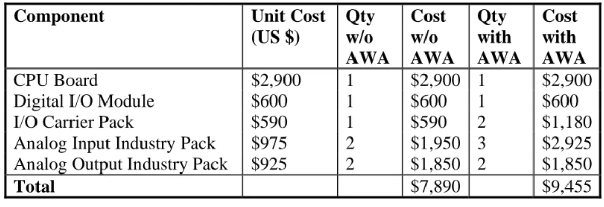
Hardware Selection v 1.00.doc Status: Final 12 The table below shows the expected cost of the off-the-shelf, board-level products for an MCU. The costs are identical for both a 24-segment MCU and a 32-segment MCU. The table includes quantities and costs for systems with active wave absorption (AWA) (3 feedback sensors) and without active wave absorption (2 feedback sensors).
Component Unit Cost
(US $) Qty w/o AWA Cost w/o AWA Qty with AWA Cost with AWA CPU Board $2,900 1 $2,900 1 $2,900
Digital I/O Module $600 1 $600 1 $600
I/O Carrier Pack $590 1 $590 2 $1,180
Analog Input Industry Pack $975 2 $1,950 3 $2,925
Analog Output Industry Pack $925 2 $1,850 2 $1,850
Total $7,890 $9,455
Table 9 – Costs per MCU for cPCI 5.4.1. 3U cPCI Option
The 3U proposal submitted by SMA Computers is shown in the table below. The final cost of the board-level hardware for a system without wave absorption capabilities exceeds the cost of the other options and, therefore, is not a viable option. Also, the analog I/O board includes 16 analog input channels with 8 analog output channels. This is not a good fit for the control system since coupling analog input and output increases the cost for the Davis Engineering motor-based wave generator. It also requires more extensive software modifications since one board can no longer handle all of the analog input for the up to 32 segments per MCU.
Component Recommendation System Cost
w/o AWA (US $)
CPU Board CPU6.2E-1101.101 $2,190
Digital I/O Board CCIO32-0 $490
Analog I/O CADIO (4 required) $8600 (for 4)
Total $11,280
Table 10 - 3U Proposal
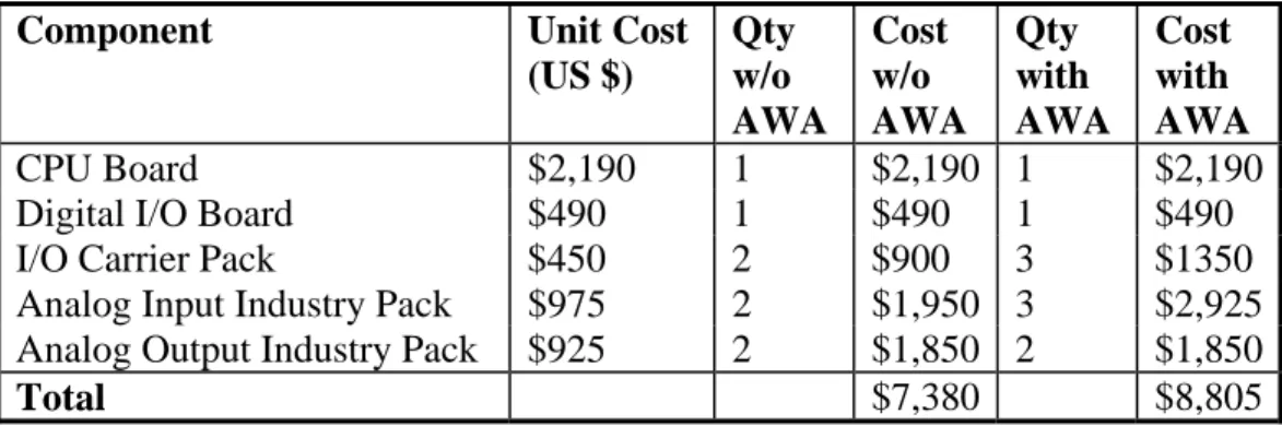
However, using the Acromag hardware for analog I/O reduces the cost of the hardware considerably. The tables below show the recommended components for a 3U system and the costs of the board-level hardware for 24-segment and 32-segment MCUs.
Component Recommendation Cost (US $)
CPU Board CPU6.2E-1101.101 $2,190
Digital I/O Board CCIO32-0 $490
I/O Carrier Pack Acromag ACPC8635 $450
Analog Input Industry Pack Acromag IP330 $975
Analog Output Industry Pack Acromag IP221 $925
Hardware Selection v 1.00.doc Status: Draft 13
Component Unit Cost
(US $) Qty w/o AWA Cost w/o AWA Qty with AWA Cost with AWA CPU Board $2,190 1 $2,190 1 $2,190
Digital I/O Board $490 1 $490 1 $490
I/O Carrier Pack $450 2 $900 3 $1350
Analog Input Industry Pack $975 2 $1,950 3 $2,925
Analog Output Industry Pack $925 2 $1,850 2 $1,850
Total $7,380 $8,805
Table 12 - Revised Costs Per MCU for 3U cPCI
The features of the CPU6.2 board were rated to obtain a ranking score of 54.3. This score makes it
the highest ranked of the cPCI options and 4th on the list including both VME and cPCI.
5.5. Custom
Digital
Board
The custom digital board is a relatively simple digital board designed to provide the following functionality:
• Sense the shorting of a set of sense points used in the calibration of wave probes mounted on the face of the wave generator (not currently used in the segmented wave generator) • Sense the closing of a number of optical sense points that may have been used for the
calibration of the position transducers at one time (no longer used)
• Hydraulic interlock loop – a loop including all MCUs designed to allow any MCU to disable the hydraulic power-pack in the event of a critical failure
• Hardware watchdog timer – designed to open a hydraulic interlock loop if the timer expires
• 100 Hz drive signal clock – the ability to source a 100 Hz signal or track a 100 Hz signal generated from another MCU. One MCU in the system provides the control clock (100 Hz) for all MCUs in the system
• Drive signal start/stop enable – the signal generated by a master MCU to indicate that the controllers are to start or stop following a drive signal
If the control system is migrated to the cPCI bus, this board will require a respin. Given the simplicity of the board, it should be possible to manufacture new boards in small quantities (10 to 15) at a cost of less than $200 US per board.
Hardware Selection v 1.00.doc Status: Final 14
6. Final Recommendations
Based on the analysis above, the lowest cost alternative is the cost-reduced 3U cPCI option. This option is approximately $400 US less than the leading the VME option and the leading 6U cPCI option. The additional cost of reworking the digital board offsets part of the cost difference relative to the VME option but the 3U cPCI remains the least expensive. Chassis costs have not been
included in this analysis but the cost of a 3U chassis will be less than the cost of a 6U chassis. However, the 3U form-factor does not allow a custom backplane to be used along with the standard cPCI backplane. This limits the design for both motor-based controller installations and the custom J2 backplane used by IOT. The recommended form-factor is, therefore, a 6U form-factor.
The recommend bus standard is the VME standard for the following reasons: • The top-ranked CPU boards are VME boards
• Given the VME CPU recommended, the existing chassis – both the vertical-oriented, rack-mounted versions currently in use and the horizontal-oriented development chassis can continue to be used.
• The custom digital signal boards (Davis Engineering and IOT) can continue to be used as they are
• The Davis Engineering custom position feedback digital board for motor-based controllers can continue to be used
• The hardware cost differential between the 6U VME and the 6U cPCI is insignificant The recommended analog I/O hardware is the Acromag carrier-pack and industry-pack solutions presented earlier. The analog output resolution should, however, be increased to 16 bits.
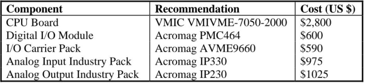
The table below identifies the final recommended choices for the system components.
Component Recommendation Cost (US $)
CPU Board VMIC VMIVME-7050-2000 $2,800
Digital I/O Module Acromag PMC464 $600
I/O Carrier Pack Acromag AVME9660 $590
Analog Input Industry Pack Acromag IP330 $975
Analog Output Industry Pack Acromag IP230 $1025
Table 13 - Final Recommendations
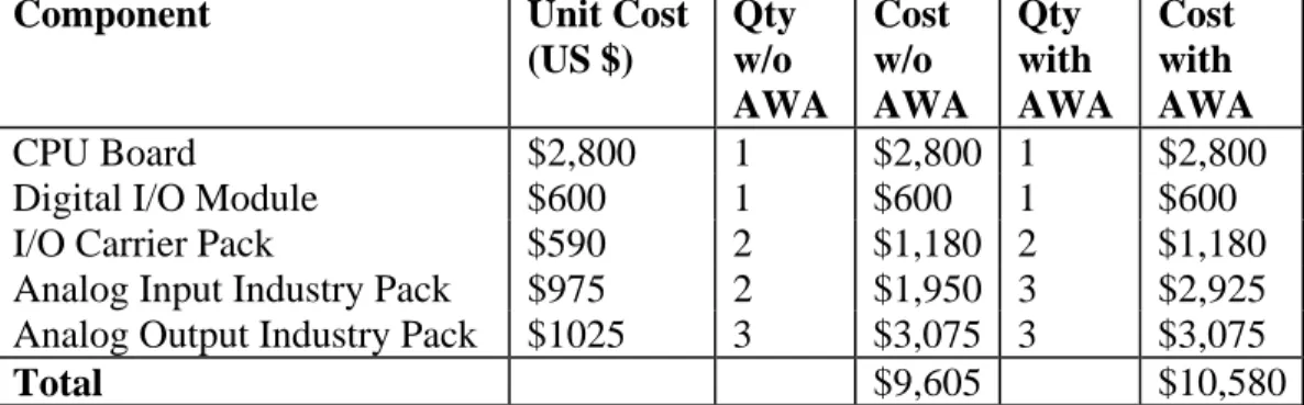
The tables below show the final expected cost of the off-the-shelf, board-level products for a 24-segment MCU and for a 32-24-segment MCU. The tables include quantities and costs for systems with active wave absorption (AWA) (3 feedback sensors) and without active wave absorption (2 feedback sensors).
Hardware Selection v 1.00.doc Status: Draft 15
Component Unit Cost
(US $) Qty w/o AWA Cost w/o AWA Qty with AWA Cost with AWA CPU Board $2,800 1 $2,800 1 $2,800
Digital I/O Module $600 1 $600 1 $600
I/O Carrier Pack $590 2 $1,180 2 $1,180
Analog Input Industry Pack $975 2 $1,950 3 $2,925
Analog Output Industry Pack $1025 3 $3,075 3 $3,075
Total $9,605 $10,580
Table 14 - MCU Cost for a 24-Segment Control System
Component Unit Cost
(US $) Qty w/o AWA Cost w/o AWA Qty with AWA Cost with AWA CPU Board $2,800 1 $2,800 1 $2,800
Digital I/O Module $600 1 $600 1 $600
I/O Carrier Pack $590 2 $1,180 2 $1,180
Analog Input Industry Pack $975 2 $1,950 3 $2,925
Analog Output Industry Pack $1025 4 $4,100 4 $4,100
Total $10,630 $11,605
Table 15 - MCU Cost for a 32-Segment Control System
6.1. Points to Note
The following notes summarize some key points in the proposal: • Additional BSP support is required for the CPU board
• One serial connection will be via the P2 connector at the rear of the CPU board • All analog I/O is terminated on the front panel of the analog I/O carrier packs • The digital I/O is terminated on the front panel of the CPU board
• This is a 3-slot solution
• The cost of the chassis is not included in the cost of an MCU
• Any costs for the rework of custom backplanes is not included in the cost of an MCU • The cost per MCU can be reduced by going to lower resolution D/A converters but Industry
Pack solutions for 12-bit DACs tend to be fixed at a range of +/- 10 volts rather than +/- 5 volts
Hardware Selection v 1.00.doc Status: Final 16
7. Appendix A CPU Features and Ranking
Vendor Model Age (yrs)
Cost Bus Processor Speed (GHz) Front panel access OS Support PMC sites
Bonus Features Main Features Rank
GE Fanuc (VMIC) VMIVME-7050-2000 0.5 $2,756 VME PPC 750FX/GX 1.00 2 Enet & 1 serial VxWorks, Linux 2 watchdog timer; temp and voltage sense 512 MB SDRAM, 64.5 MB bootable flash; 32K NVRAM; 2 serial I/O; dual gigE, 5V, +/-12V 1 GE Fanuc
(VMIC)
VMIVME-7700-121
0 $2,601 VME Intel Celeron 0.65 2 Enet & 2 serial VxWorks, Linux, Windows, QNX 1 watchdog timer; byte swapping h/w, compactFlash, Enet boot 512 MB SDRAM, 128 MB flash; 32K NVRAM; 2 serial I/O; dual 10/100 Ethernet, 5V, +/-12V
2 SBS VG5 0.9 $3,531 VME PPC 7455/57 0.80 2 Enet &
2 serial VxWorks, LynxOS, Linux 1 Conformal coating, temp sense, watchdog, fanless cooling 512 MB SDRAM, 64 MB flash, 24K NVRAM; 6 serial I/O; 1 gigE, 1 10/100 BT, 5V, 3.3V 3 SMA Computers CPU6.2E-1101.101
1.5? $2,190 cPCI Pentium III (VIA) 1.00 1 Enet & 2 serial Win CE, Linux, QNX 0 watchdog, CPU temp alarm, fan
128 MB SDRAM, 512 KB NVRAM, 32 MB compactFlash, 2 100 BT, 2 USB, 2 serial 4 Motorola MVME5500 1.4 $3,295 VME PPC 7455 1.00 2 Enet &
1 serial
VxWorks, Linux, LynxOS
2 watchdog 512 MB SDRAM, 32 + 8 MB flash; 32 KB NVRAM, 2 serial I/O; gigE & 10/100 BT, 5V 5 GE Fanuc
(VMIC)
VMICPCI-7806-111
0.25 $2,925 cPCI Pentium-M 1.10 2 Enet & 1 serial VxWorks, Linux, Windows, QNX 2 compactFlash, bootp, watchdog 512 MB SDRAM, 128 MB flash; 0 NVRAM; 2 serial I/O; 2 USB; dual gigE 6 SBS VG4 1.4 $2,700 VME PPC 7410/750/755 0.50 nothing VxWorks, LynxOS, Linux 2 Conformal coating; 16-bit TTL I/O, temp sense, watchdog 512 MB SDRAM, 64 MB flash; 512 KB bootable flash; 32K NVRAM; 4 serial I/O; single gigE, 5V, +/-12V
7 Force PowerCore
CPCI-695
0.5 $4,500 cPCI PPC 750FX 0.80 1 Enet & 2 serial
VxWorks, Linux
2 watchdog 512 MB SDRAM, 64 MB flash, 512 KB bootflash, 64 KB NVRAM, 3 gigE, 2 serial I/O, 8 Force PowerCore
CPU-695
0.5 $4,700 VME PPC 750FX 0.80 1 Enet & 2 serial VxWorks, Linux 2 watchdog timers, failsafe bootflash (1MB) 512 MB SDRAM, 64 MB flash, 1 MB bootflash, 32 KB NVRAM,
dual gigE, 2 serial I/O, 5V, 3.3V 9 Motorola CPN5385 1.7 $2,995 cPCI Pentium III-M 1.20 1 serial Win 2k,
Linux, VxWorks 1 watchdog, CPU temp alarm, 512 MB SDRAM, 2 gigE, 1 10/100 BT, 4 USB, 2 serial, 10 SBS CT7 2 $2,700 cPCI Celeron 0.57 2 Enet &
1 serial & 1 USB NT, Win, QNX, VxWorks, Lynx, Linux 1 watchdog, temp sense
512 MB SDRAM, flashdrive (up to 512 MB), 2 10/100 BT, 2 serial I/O, 2 USB, 0 NVRAM
11 SBS CR9 0.2 $4,200 cPCI Pentium-M 0.60 2 Enet &
1 serial & 1 USB QNX, VxWorks, LynxOS, Linux 1 watchdog, temp sense, conformal coating
512 MB SDRAM, flashdrive (up to 1 GB), 2 gigE, 2 serial I/O, 5 USB, 64 KB NVROM
12 SBS CT9 0.2 $4,200 cPCI Pentium-M 0.60 2 Enet &
1 serial & 1 USB QNX, VxWorks, LynxOS, Linux 1 watchdog, temp sense
512 MB SDRAM, flashdrive (up to 1 GB), 2 gigE, 2 serial I/O, 5 USB, 64KB NVROM
13 Force CPCI-745 1 $3,300 cPCI Pentium-M 1.60 1 Enet 1 watchdog timer,
compactFlash
512 MB SDRAM, 8 MB flash, 2 gigE & 1 10/100 BT, 2 USB, 2
serial, 0 NVRAM 14 SBS Power7E 3 VME PPC 750 0.53 1 Enet &
1 serial
VxWorks 1 256 MB SDRAM, 4 MB flash, 512 KB socketed flash, 32 KB NVRAM, single 10/100 BT, 2
serial, 5V, +/-12V 15 Motorola MCP820 2 $3,995 cPCI PPC 7410 0.50 1 Enet, 1
serial & 2 USB
1 watchdog 512 MB SDRAM, 32 MB flash, 1 MB bootflash, 32 KB NVRAM,
Hardware Selection v 1.00.doc Status: Draft 17
Vendor Model Age
(yrs) Age (yrs)
Cost Cost Bus Bus CPU CPU BSP Maturity BSP Maturity Front panel access Front panel access OS Sup OS Sup Bonus feat Bonus feat Main feat Main feat Points Rank Weight 1 1 0.7 0.7 0.8 0.7 0.6 0.5 0.7 0 VMIC VMIVME-7050-2000 10.0 10.0 8.0 8.0 10.0 7.0 10.0 7.0 8.0 6.4 8.0 5.6 7.5 4.1 5.0 2.5 10.0 7.0 57.6 1 VMIC VMIVME-7700-121 10.0 10.0 8.0 8.0 10.0 7.0 6.0 4.2 8.0 6.4 10.0 7.0 10.0 5.5 4.0 2.0 10.0 7.0 57.1 2 SBS VG5 8.0 8.0 4.0 4.0 10.0 7.0 10.0 7.0 10.0 8.0 10.0 7.0 10.0 5.5 7.0 3.5 10.0 7.0 57.0 3 SMA Computers CPU6.2E-1101.101 6.0 6.0 10.0 10.0 8.0 5.6 6.0 4.2 10.0 8.0 10.0 7.0 10.0 5.5 2.0 1.0 10.0 7.0 54.3 4 Motorola MVME5500 6.0 6.0 6.0 6.0 10.0 7.0 10.0 7.0 10.0 8.0 8.0 5.6 10.0 5.5 4.0 2.0 10.0 7.0 54.1 5 VMIC VMICPCI-7806-111 10.0 10.0 8.0 8.0 8.0 5.6 8.0 5.6 6.0 4.8 8.0 5.6 10.0 5.5 6.0 3.0 8.0 5.6 53.7 6 SBS VG4 6.0 6.0 8.0 8.0 10.0 7.0 10.0 7.0 10.0 8.0 0.0 0.0 10.0 5.5 9.0 4.5 10.0 7.0 53.0 7 Force PwrCore CPCI-695 10.0 10.0 2.0 2.0 8.0 5.6 10.0 7.0 8.0 6.4 10.0 7.0 7.5 4.1 4.0 2.0 10.0 7.0 51.1 8 Force PwrCore CPU-695 10.0 10.0 0.0 0.0 10.0 7.0 10.0 7.0 8.0 6.4 10.0 7.0 7.5 4.1 5.0 2.5 10.0 7.0 51.0 9 Motorola CPN5385 4.0 4.0 8.0 8.0 8.0 5.6 6.0 4.2 10.0 8.0 6.0 4.2 10.0 5.5 5.0 2.5 8.0 5.6 47.6 10 SBS CT7 4.0 4.0 8.0 8.0 8.0 5.6 6.0 4.2 10.0 8.0 9.0 6.3 10.0 5.5 2.0 1.0 7.0 4.9 47.5 11 SBS CR9 10.0 10.0 2.0 2.0 8.0 5.6 8.0 5.6 4.0 3.2 9.0 6.3 10.0 5.5 7.0 3.5 7.0 4.9 46.6 12 SBS CT9 10.0 10.0 2.0 2.0 8.0 5.6 8.0 5.6 4.0 3.2 9.0 6.3 10.0 5.5 5.0 2.5 7.0 4.9 45.6 13 Force CPCI-745 8.0 8.0 6.0 6.0 8.0 5.6 8.0 5.6 10.0 8.0 6.0 4.2 0.0 5.0 2.5 8.0 5.6 45.5 14 SBS Power7E 0.0 0.0 8.0 8.0 10.0 7.0 10.0 7.0 10.0 8.0 8.0 5.6 5.0 2.8 0.0 0.0 9.0 6.3 44.7 15 Motorola MCP820 4.0 4.0 4.0 4.0 8.0 5.6 10.0 7.0 10.0 8.0 9.0 6.3 0.0 1.0 0.5 10.0 7.0 42.4 16
AcPC8625
CompactPCI
®,
Non-intelligent,
IP Carrier Card
The AcPC8625 is a non-intelligent slave board that interfaces four IP modules to the CompactPCI (cPCI) bus. All 200 I/O points are brought out the rear J4 and J5 connectors. This convenience eliminates messy cables from hanging out the front of the cage. In addition to a more efficient cage wiring design, it is also much easier to insert and replace boards. And with Acromag’s 80mm transition module (TRANS-C200), all 200 I/O points are easily ported out the back of the cage.
Features
■Four industry-standard IP module slots ■Board resides in memory space and ■Supports IP module I/O, ID and INT spaces ■200 I/O points with rear access ■High-density rear connectors ■Compatible with all CompactPCI CPUs ■Plug-and-play carrier configuration and
interrupt support ■Two interrupts per IP module ■Front panel LEDs
■Supervisory circuit for reset generation ■Individually filtered and fused power to each IP ■Ruggedized with ESD strip and EMC front panel ■ActiveX/OLE controls available for easy software
integration (sold separately)
Benefits
■Clean system cabling. ■Easy board replacement.
■Simplified debugging with status LEDs.
Operation
Acromag’s carrier boards provide full data access to the IP module’s I/O, ID and interrupt spaces. With full access to the programmable registers, you can easily configure and control the operation of the IP modules from the CompactPCI bus.
Up to two interrupt requests are supported for each IP module. All board interrupts are mapped to PCI bus INTA# signal.
Individual passive filters on each IP power supply line provide optimum filtering and noise isolation between the IP modules and the carrier board.
Specifications
IP Compliance (ANSI/VITA 4)Meets IP specs per ANSI/VITA 4-1995 (8MHz operation only) and IP I/O mapping to PICMG 2.4 R1.0.
Electrical/mechanical interface:
Supports single or double size IP modules. 32-bit IP modules are not supported.
IP Module I/O space, ID space, and INT space supported. Memory space: Not supported.
Interrupts: Supports two interrupt requests per IP module and interrupt acknowledge cycles via access to IP INT space.
CompactPCI bus Compliance
Meets PCI spec. V2.1 and PICMG 2.0, R2.1.
Data transfer bus: Slave with 32-bit, 16-bit, and 8-bit data transfer operation 32-bit read/write accesses are imple-mented as two 16-bit transfers to the IPs.
Interrupts: CompactPCI bus INTA# interrupt signal. Up to two requests sourced from each IP mapped to INTA#. Interrupt vectors come from IP modules via access to IP module INT space.
Plug-and-Play: The system maps the base address into the PCI bus 32-bit memory space.
Environmental
Operating temperature: -25 to 85°C (AcPC8625) or -40 to 85°C (AcPC8625E models). Storage temperature: -25 to 85°C (AcPC8625)
or -40 to 85°C (AcPC8625E models). Relative humidity: 5 to 95% non-condensing. Power:
+5V (±5%): 250mA maximum. ±12V (±5%): 0mA (not used). Plus IP module load.
MTBF: 409,808 hrs. at 25°C, MIL-HDBK-217F, notice 2.
Ordering Information
Industry Pack CarriersAcPC8625: CompactPCI carrier. Holds four IP modules. AcPC8625E: Same as AcPC8625 plus extended temp.range.
Software (see Page 81)
IPSW-API-VXW: VxWorks®software support package
IPSW-API-QNX: QNX®software support package
IPSW-ATX-PCI: ActiveX®/OLE Controls 2.0 software package
IPSW-LINUX: Linux™support (website download only)
Accessories (see Page 87)
5028-438: Cable, SCSI-2 to SCSI-2, shielded. 5028-378: Termination panel, SCSI-2 connector,
50 screw terminals
TRANS-C200: Transition module
Acromag, Inc. • PO Box 437, Wixom, MI 48393 • Phone: 248-624-1541 • Fax: 248-624-9234 • [email protected] • www.acromag.com
8
Mix and match plug-in modules with different I/O functions to quickly create custom I/O boards with hundreds of channels.
Industr y P ack Carriers ACPC8625 TRANS-C200 cPCI Bac kplane
AcPC8635
CompactPCI
®,
Nonintelligent,
3U IP Carrier Card
The AcPC8635 is a nonintelligent slave board that inter-faces two IP modules to the CompactPCI®(cPCI) bus.
All 100 I/O points are brought out the rear J2 connector. This convenience eliminates messy cables from hanging out the front of the cage. In addition to a more efficient cage wiring design, it is also much easier to insert and replace boards.
Features
■Two industry-standard IP module slots ■Board resides in memory space ■Supports IP module I/O, ID and INT spaces ■100 I/O points with rear access ■High-density rear connectors
■Compatible with 32-bit CompactPCI®backplane ■Plug-and-play carrier configuration and
interrupt support
■Two interrupt channels per IP module ■Front panel LEDs
■Supervisory circuit for reset generation ■Individually filtered and fused power to each IP ■Ruggedized with ESD strip and EMC front panel ■ActiveX/OLE controls available for easy software
integration (sold separately)
Benefits
■Clean system cabling.
■Easy board replacement as I/O needs change. ■Simplified debugging with status LEDs. ■Quick development of custom I/O boards. ■Flexibility to mix and match I/O functions as
requirements change.
Operation
Acromag’s carrier boards provide full data access to the IP module’s I/O, ID and interrupt spaces. With full access to the programmable registers, you can easily configure and control the operation of the IP modules from the cPCI bus.
Up to two interrupt requests are supported for each IP module. All board interrupts are mapped to PCI bus INTA# signal.
Individual passive filters on each IP power supply line provide optimum filtering and noise isolation between the IP modules and the carrier board.
Specifications
IP Compliance (ANSI/VITA 4)Meets IP specs per ANSI/VITA 4-1995 (8MHz operation only) and IP I/O mapping to J2 per PICMG 2.4 R1.0. Electrical/mechanical interface:
Supports single or double size IP modules. 32-bit IP modules are not supported.
IP Module I/O space, ID space, and INT space supported. IP Module Memory space: Not supported.
Interrupts: Supports two interrupt requests per IP module and interrupt acknowledge cycles via access to IP INT space.
CompactPCI bus Compliance
Meets PCI spec. V2.1 and PICMG 2.0, R2.1.
Data transfer bus: Slave with 32-bit, 16-bit, and 8-bit data transfer operation. 32-bit read/write accesses are imple-mented as two 16-bit transfers to the IPs.
Interrupts: CompactPCI bus INTA# interrupt signal. Up to two requests sourced from each IP mapped to INTA#. Interrupts come from IP modules via access to IP module INT space. 32-bit memory space: Upon power-up, the system
auto-configuration process (plug & play) maps the carrier's base address (for a 1K byte block of memory) into the PCI bus 32-bit memory space.
Environmental
Operating temperature: 0 to 70°C (AcPC8635 model) or -40 to 85°C (AcPC8635E model).
Storage temperature: -55 to 100°C. Relative humidity: 5 to 95% non-condensing. Power:
+5V (±5%): 200mA maximum. ±12V (±5%): 0mA (not used). Plus IP module load. MTBF: Consult factory.
Ordering Information
Industry Pack CarriersAcPC8635: CompactPCI carrier. Holds two IP modules. AcPC8635E: Same as AcPC8635 with extended temp.range.
Software (see Page 81)
IPSW-API-VXW: VxWorks®software support package
IPSW-API-QNX: QNX®software support package
IPSW-ATX-PCI: ActiveX®/OLE Controls 2.0 software package
IPSW-LINUX: Linux™support (website download only)
Accessories (see Page 87)
5025-550: Cable, unshielded, 50-pin header both ends 5025-551: Same as 5025-550 except shielded 5025-552: Termination panel, 50-pin connector,
50 screw terminals
TRANS-C100: Transition module
Acromag, Inc. • PO Box 437, Wixom, MI 48393 • Phone: 248-624-1541 • Fax: 248-624-9234 • [email protected] • www.acromag.com
10
Mix and match plug-in modules with different I/O functions to quickly create custom I/O boards.
Industr y P ack Carriers TRANS-C100 ACPC8635 CompactPCI Backplane J1 A1 F1 F25A25 F1A1 P1 D1 A P2 P4 B P3 J2 A22 F22 A22F22 SLOT B J2 F1 A1 SLOT A TP1 GND P1
AVME9630/60
VMEbus 3U/6U,
Non-intelligent,
IP Carrier Cards
The AVME9630 and AVME9660 are non-intelligent slave boards that interface IP modules to the VMEbus. The full-height (6U) board holds four IP modules, and the half-height (3U) board holds two. All field I/O connections are made to the carrier board.
Features
■6U VMEbus card holds four IP modules, 3U model holds two modules ■ Industry-standard IP module interface ■Front panel connectors for field I/O signals ■Supports two interrupt channels per IP ■Provides individually isolated and filtered +5V,
+12V, and -12V DC power lines to each IP module ■Accepts other manufacturers’IP modules ■Locking front panel connectors
Benefits
■Full IP module data access enables convenient soft-ware configuration and control of the IP modules. ■Front panel LEDs simplify debugging with a visual
indication of successful IP accesses.
■Front panel connectors provide ribbon cable access to field I/O without interference from boards in adjacent slots.
Operation
Acromag’s carrier boards provide full data access to the IP module’s I/O, ID and memory spaces. With full access to the programmable registers, you can easily configure and control the operation of the IP modules from the VMEbus.
Up to two interrupt requests are supported for each IP module. The VMEbus interrupt level is software programmable.
Individual passive filters on each IP module power supply line provide optimum filtering and isolation between the IP modules and the carrier board.
Specifications
IP Compliance (ANSI/VITA 4)Meets IP specifications per ANSI/VITA 4-1995. Electrical/mechanical interface:
Supports single or double size IP modules. 32-bit IP modules are not supported. I/O space and ID space supported.
Memory space: Supports 1MB to 8MB per IP module. Interrupts: Supports two interrupt requests per IP module and
interrupt acknowledge cycles, D16/D08(O).
VMEbus Compliance
Meets VME specifications per revision C.1 dated October 1985, IEC 821-1987 and IEEE 1014-1987.
Data transfer bus: A24/A16:D16/D08(EO) DTB slave; supports Read-Modify-Write cycles.
Interrupts: Creates I(1-7) programmable request levels (up to two requests sourced from each IP module). D16/D08(O) interrupter (interrupt vectors come from IP modules). Carrier registers are for control and status monitoring. Interrupt release mechanism is Release on Register Access (RORA) type.
Environmental
Operating temperature: 0 to 70°C (AVME9630/60) or -40 to 85°C (AVME9630E/60E models). Storage temperature: -25 to 85°C (AVME9630/60)
or -40 to 85°C (AVME9630E/60E models). Relative humidity: 5 to 95% non-condensing. Power:
+5V (±5%): 275mA maximum. ±12V (±5%): 0mA (not used). Plus IP module load.
MTBF: 453,851 hrs. at 25°C, MIL-HDBK-217F, notice 2.
Ordering Information
Industry Pack CarriersAVME9630
3U carrier. Holds two IP modules.
AVME9630E
Same as AVME9630 plus extended temperature range.
AVME9660
6U carrier. Holds four IP modules.
AVME9660E
Same as AVME9660 plus extended temperature range.
Software (see Page 81)
IPSW-API-VXW
VxWorks®software support package
Accessories (see Page 87)
5025-550: Cable, unshielded, 50-pin header both ends 5025-551: Same as 5025-550 except shielded 5025-552: Termination panel, 50-pin connector,
50 screw terminals
TRANS-GP: Transition module
Acromag, Inc. • PO Box 437, Wixom, MI 48393 • Phone: 248-624-1541 • Fax: 248-624-9234 • [email protected] • www.acromag.com
6
Mix and match plug-in modules with different I/O functions to quickly create custom I/O boards with hundreds of channels.
Industr
y P
ack Carriers
Acromag, Inc. • PO Box 437, Wixom, MI 48393 • Phone: 248-624-1541 • Fax: 248-624-9234 • [email protected] • www.acromag.com
15
IP220-x
12-Bit D/A,
Analog Output
The IP220 outputs analog voltage signals to drive up to 16 devices. When used with a carrier that holds four IP modules, up to 64 voltage outputs can be obtained from a single card cage slot.
Each output channel has its own 12-bit D/A converter (DAC). Individual DACs are faster, and they eliminate glitches typically caused by the re-acquisition process of sample and holds found on multiplexed output boards. Individual channels also have double-buffered data latches. You can select to update each output when it is written to, or to update all outputs simultaneously. Simultaneous outputs better simulate linear move-ments in motion processes.
Features
■8 or 16 analog voltage output channels
■Independent 12-bit D/A converters per channel with an 8.0µS settling time
■Bipolar voltage (non-isolated) outputs: -10 to +10 volts
■Double-buffered DACs
■High load capability (5mA output current) ■Built-in calibration coefficients
Benefits
■Outputs reset to 0 volts.■Internally stored calibration coefficients ensure accuracy.
■Software provides easy selection of transparent or simultaneous output modes.
■Double-buffered DACs allow new data to be written to each channel before the simultaneous trigger updates the outputs.
Specifications
Analog OutputsOutput configuration: 8 or 16 single-ended. D/A Resolution: 12 bits.
Output range: Bipolar, -10 to +10V. Maximum throughput rate:
Outputs can be updated simultaneously or individually. One channel: 121KHz (8.25µS/conversion)
Eight channels (IP220-8): 100KHz (10µS/8 ch) Sixteen channels (IP220-16): 83KHz (12µS/16 ch). System accuracy: 0.025% of 20V span maximum
corrected error (i.e. calibrated) at 25°C with the output unloaded.
Data format (left–justified): Bipolar Offset Binary. Output at reset: 0 volts.
Output current: -5 to +5mA (maximum). Short circuit protection: Indefinite at 25°C.
IP Compliance (ANSI/VITA 4)
Meets IP specifications per ANSI/VITA 4-1995. IP data transfer cycle types supported:
Input/output (IOSel*): DAC data, control registers, DAC offset and gain calibration coefficients. ID read (IDSel*): 32 x 8 ID PROM. Access Times (8MHz clock): 0 wait states.
Environmental
Operating temperature: 0 to 70°C (IP220-8/16) or -40 to 85°C (IP220-8E/16E models). Storage temperature: -55 to 100°C (all models). Relative humidity: 5 to 95% non-condensing MTBF: 581,396 hrs at 25°C, MIL-HDBK-217F, Notice 2. Power: +5V: 200mA.
+12V from P1 or +15V from P2: 300mA. -12V from P1 or -15V from P2: 180mA.
Ordering Information
Industry Pack ModulesIP220-8
Eight voltage outputs
IP220-8E
Same as IP220-8 plus extended temperature range.
IP220-16
Sixteen voltage outputs
IP220-16E
Same as IP220-16 plus extended temperature range.
For Industry Pack Carrier Cards, see Page 5.
Software (see Page 81)
IPSW-API-VXW
VxWorks®software support package
IPSW-API-QNX
QNX®software support package
IPSW-ATX-PCI
ActiveX®/OLE Controls 2.0 software package
IPSW-LINUX
Linux™support (website download only) For accessories information, see Page 87.
The IP220 features individual D/A converters on each channel for better performance.
Industr
y P
IP230-x
16-Bit D/A
Analog Output
IP230 modules have a 16-bit D/A converter (DAC) to provide highly-accurate analog voltage outputs. Jumper-selectable output ranges give you the choice of unipolar or bipolar voltage output. And for greater flexibility, the IP230 module accepts conversion start triggers from software commands, or from external sources for synchronization to specific events.
Features
■IP230-4: 4 analog voltage output channels IP230-8: 8 analog voltage output channels ■Individual 16-bit D/A converters per channel ■10µS settling time (100KHz throughput) ■Three output ranges: ±5V, ±10V, 0 to 10V
(jumper-selectable) ■Two trigger modes
(software or external trigger) ■External trigger output
■Extended temperature option (-40 to 85°C)
Benefits
■High channel density saves card cage slots. ■Internally stored calibration coefficients
ensure accuracy.
■Flexible output control allows single cycle updating of individual channels or all channels simultaneously. ■Hardware jumpers allow output range selection on
an individual channel basis.
Specifications
Analog OutputsOutput configuration: 4 (IP230-4/4E) or 8 (-8/8E). D/A Resolution: 16 bits.
Output ranges: ±5V, ±10V, 0 to 10V (jumper-selectable). Maximum throughput rate:
Outputs can be updated simultaneously or individually. One channel: 100KHz (10µS/conversion)
Four channels (IP235-4): 100KHz (10µS/4 ch) Eight channels (IP235-8): 100KHz (10µS/8 ch). DAC programming: Immediate (transparently
programmed to DAC output); simultaneous (input latches of multiple DACs are loaded with new data before simultaneously updating outputs). System accuracy: 0.0061% of 20V span maximum
corrected error (i.e. calibrated) at 25°C with the output unloaded.
Output at reset: 0V for bipolar output, 5V for unipolar. Output current: -5 to +5mA (maximum). Short circuit protection: Indefinite at 25°C.
IP Compliance (ANSI/VITA 4)
Meets IP specifications per ANSI/VITA 4-1995. IP data transfer cycle types supported:
Input/output (IOSel*), ID read (IDSel*). Access Times (8MHz clock):
All functions: 1 wait state (375nS cycle).
Environmental
Operating temperature: 0 to 70°C (IP230-4/8) or -40 to 85°C (IP230-4E/8E models). Storage temperature: -55 to 125°C (all models). Relative humidity: 5 to 95% non-condensing Power: +5V (±5%): 200mA maximum.
±12V (±5%) from P1: 150mA maximum. MTBF: 815,720 hrs. at 25°C, MIL-HDBK-217F, notice 2.
Ordering Information
Industry Pack ModulesIP230-4
Four high-resolution voltage outputs
IP230-4E
Same as IP230-4 plus extended temp. range
IP230-8
Eight high-resolution voltage outputs
IP230-8E
Same as IP230-8 plus extended temp. range
For Industry Pack Carrier Cards, see Page 5.
Software (see Page 81)
IPSW-API-VXW
VxWorks®software support package
IPSW-API-QNX
QNX®software support package
IPSW-ATX-PCI
ActiveX®/OLE Controls 2.0 software package
IPSW-LINUX
Linux™support (website download only) For accessories information, see Page 87.
Acromag, Inc. • PO Box 437, Wixom, MI 48393 • Phone: 248-624-1541 • Fax: 248-624-9234 • [email protected] • www.acromag.com
16
Independent D/A converters on each channel provide better performance and smoother operation.
Industr
y P
IP330
16-Bit A/D
Analog Input
IP330 Industry Pack (IP) modules provide fast, high resolution A/D conversion.
The IP330 has many features to improve your overall system throughput rate. You can scan all channels or define a subset for more frequent sampling. Burst mode scans selected channels at the maximum conversion rate. Uniform mode performs conversions at user-defined intervals. Both modes can scan continuously, or execute a single cycle upon receiving a trigger. “Mail box”memory allows the CPU to read the latest data in 32 storage buffer registers without interrupting the A/D converter.
Features
■16-bit A/D converter (ADC) ■8µS conversion time (125KHz) ■16 differential or 32 single-ended inputs
(±5V, ±10V, 0-5V, and 0-10V input ranges) ■Individual channel mailbox with one or two
storage buffer registers per channel ■Programmable scan control ■Four scanning modes
■User-programmable interval timer ■External trigger input and output ■Programmable gain for individual channels ■Post-conversion interrupts
Benefits
■“Mailbox”memory eliminates scanning interruptions for optimum throughput. ■Data register indicates new and missed
(overwritten) data values in the mail box. ■Programmable interrupts simplify data
acquisition by providing greater control.
Specifications
Analog InputsInput configuration: 16 differential or 32 single-ended. A/D resolution: 16 bits.
Input ranges: ±5V, ±10V*, 0-5V, and 0-10V*. * Requires ±15V external supplies.
Data sample memory: Individual channel mailbox with one or two storage buffer registers per channel.
Maximum throughput rate:
Only one channel can be updated at a time. One channel: 125KHz maximum (8µS/conversion) [66KHz (15µS/conversion) recommended] 16 channels (differential): 4.2KHz (240µS/16 ch) 32 channels (single-ended): 2.1KHz (480µS/32 ch). Programmable gains: 1x, 2x, 4x, 8x.
A/D triggers: External and software. System accuracy: 2 LSB (0.0030%) typical
(SW calib., gain=1, 25°C).
Data format: Straight binary or two’s compliment. Input overvoltage protection: Vss -20V to Vdd 40V with
power on, -35V to 55V power off.
Common mode rejection ratio (60Hz): 96dB typical. Channel-to-channel rejection ratio (60Hz): 96dB typical.
IP Compliance (ANSI/VITA 4)
Meets IP specifications per ANSI/VITA 4-1995.
IP data transfer cycle types supported: Input/output (IOSel*), ID read (IDSel*), Interrupt select (INTSel*).
Access times (8MHz clock):
ID PROM read: 1 wait state (375ns cycle). Channel port/register read/write: 0 wait states. Interrupt select cycle read: 1 wait state. Mail box I/O read: 1 wait state. 6 wait states
if ongoing internal mail box write.
Environmental
Operating temperature: 0 to 70°C (IP330) or -40 to 85°C (IP330E model). Storage temperature: -55 to 100°C. Relative humidity: 5 to 95% non-condensing. MTBF: 798,625 hrs at 25°C, MIL-HDBK-217F, Notice 2. Power:
+5V: 40mA. +12V from P1: 20mA.
-12V from P1 or ±15V through P2: 15mA.
Ordering Information
Industry Pack ModulesIP330
32 single-ended or 16 differential inputs.
IP330E
Same as IP330 plus extended temperature range
For Industry Pack Carrier Cards, see Page 5.
Software (see Page 81)
IPSW-API-VXW
VxWorks®software support package
IPSW-API-QNX
QNX®software support package
IPSW-ATX-PCI
ActiveX®/OLE Controls 2.0 software package
IPSW-LINUX
Linux™support (website download only) For accessories information, see Page 87.
Acromag, Inc. • PO Box 437, Wixom, MI 48393 • Phone: 248-624-1541 • Fax: 248-624-9234 • [email protected] • www.acromag.com
20
Advanced memory management techniques allow the IP330 to operate with minimal interruption of the A/D converter.
Industr
y P