Cache Coherence Strategies in a Many-core
Processor
MASSACHUSETTS INSTiMNiEOF TECHNOLOGY
by
AUG
2 4 2010
Christopher P. Celio
LIBRARIES
B.S., Massachusetts Institute of Technology (2008)
Submitted to the Department of Electrical Engineering and Computer
Science
in partial fulfillment of the requirements for the degree of
Master of Engineering in Electrical Engineering and Computer Science
at the
ARCHIVES
MASSACHUSETTS INSTITUTE OF TECHNOLOGY
September 2009
©
Massachusetts Institute of Technology 2009. All rights reserved.
A uthor ... .
...
Department'4 Electrical Engineering and Computer Science
August 1, 2009
Certified by...V....
...
Anant Agarwal
Professor of Computer Science & Engineering Associate Director,
Computer Science and Artificial Intelligence Laboratory
Thesis Supervisor
Accepted by ..
Dr. Christopher J. Terman
Chairman, Department Committee on Graduate Theses
Cache Coherence Strategies in a Many-core Processor
by
Christopher P. Celio
Submitted to the Department of Electrical Engineering and Computer Science on August 1, 2009, in partial fulfillment of the
requirements for the degree of
Master of Engineering in Electrical Engineering and Computer Science
Abstract
Caches are frequently employed in memory systems, exploiting memory locality to gain advantages in high-speed performance and low latency. However, as computer processor core counts increase, maintaining coherence between caches becomes in-creasingly difficult. Current methods of cache coherence work well in small-scale multi-core processors, however, the viability of cache coherence as processors scale to thousands of cores remains an open question. A novel many-core execution-driven performance simulator, called Graphite and implemented by the Carbon group, has been utilized to study a variety of cache coherency strategies of processors up to 256 cores. Results suggest that cache coherence may be possible in future many-core pro-cessors, but that software developers will have to exercise great care to match their algorithms to the target architecture to avoid sub-optimal performance.
Thesis Supervisor: Anant Agarwal
Title: Professor of Computer Science & Engineering Associate Director, Computer Science and Artificial Intelligence Laboratory
Acknowledgments
I would like to thank everyone in Carbon for their support, mentorship, and friendship. I could not have asked for a better group of people to work with. I also greatly appreciate the group effort that went into making the Graphite simulator.
I would like to thank my advisor Prof. Anant Agarwal for his support, and for helping me grow as a computer architect and researcher. I will miss the insights that he brought to every meeting. I would like to thank Jason Miller for his guidance through my Masters and for his editing of this thesis.
I would also like to thank my family and friends for their support and patience. While they are too numerous to mention, I do have to single out Kim Collins for her tremendous friendship, as well as her help in the creation of this thesis.
But most importantly, I would like to thank my parents for everything they have done in helping me get to where I am. And of course, I must thank them for carefully reading my thesis and providing very detailed feedback. I am impressed and flattered that they took the time to understand it, and that afterwards they asked all of the right questions.
Contents
1 Introduction 13
1.1 Cache Coherence in Many-core Processors . . . . 14
1.2 M oore's Law . . . . 15
1.3 The Power Wall . . . . 16
1.4 Future of Multi-core . . . . 16
2 Cache Coherence Strategies 19 2.1 Snoopy Protocol . . . . 21
2.2 Directory Protocols . . . . 21
2.3 Full-Map Directory Protocol . . . . 22
2.4 Limited-Map Directory Protocol . . . . 22
2.5 LimitLESS Protocol.. . . . . . . . . 25
2.6 Chained Directory Protocol . . . . 25
2.7 Other Strategies... . . . . . . . 26
3 The Graphite Simulator 27 3.1 The Motivation for a New Simulator . . . . 28
3.2 Graphite Simulator Features . . . . 28
3.3 The Processing Core . . . . 28
3.4 The Shared Memory System . . . . 29
3.4.1 C aches . . . . 30
3.4.2 D irectories . . . . 32
3.4.3 Cache Coherence Protocols . . . . 33 7
3.5 Interconnect Network . . . . 34
4 Experiment Methodologies and Results 35 4.1 Experimental Setup & Target Architecture . . . . 35
4.2 Blackscholes... . . . . . . . .. 36
4.2.1 Application Characteristics... . . . .. 36
4.2.2 Experimental Setup... . . . . . . . 37
4.2.3 Comparison of Different Cache Coherence Protocols . . . . 38
4.3 2D Jacobi .. . ... .. . . . . .. . . .. . . .. .. ... . . . . . 39
4.3.1 Application Characteristics . . . . 39
4.3.2 Experimental Setup... . . . . . . . .. 41
4.3.3 Comparison of Different Cache Coherence Protocols . . . . 42
4.4 Discussion... . . . . . . . 44
5 Conclusion 47
List of Figures
2-1 Example of the Cache Coherence Issue . . . . 20
2-2 Full-map Directory Protocol. . . . . 23
2-3 Limited-Map Directory Protocol. . . . . 24
3-1 Cache State Transitions . . . . 31
3-2 DRAM Directory State Transitions . . . . 32
4-1 Comparison of different cache coherency schemes in blackscholes 38 4-2 Partitioning of a 2D matrix between N threads in 2D Jacobi . . ... 40
4-3 The main loop code in 2D Jacobi . . . . 41
4-4 Comparison of different cache coherency schemes in 2D Jacobi. . . . 42
A-1 LimitLESS Protocol Simulation Code for Adding Sharers . . . . 50
List of Tables
3.1 Possible Cache States . . . . 30 3.2 Possible DRAM States . . . . 32 4.1 Target Architecture Parameters . . . ... 36
Chapter 1
Introduction
Due to the high latency suffered in accessing memory, processors have utilized high-speed buffers, or caches, to dramatically increase processor utilization, and thus, decrease run-time. By storing the most commonly used data in caches, the processor can avoid the long trips to main memory.
In a multi-core processor, each core typically maintains its own private cache. A single variable that is being shared by multiple cores may be stored in multiple caches. However, a problem of inconsistency arises if one core decides to change the variable's value in its cache. Therefore, a cache coherency strategy is needed to resolve the conflict.
As computer architectures have begun to rely on parallelization to maintain the exponential increase in computational power, maintaining cache coherency has be-come a very challenging problem. A number of solutions have been proposed and evaluated, and there exist many multi-core processors that utilize their own solutions to the cache coherence problem including the Intel Quad Core Xeon [3], the Tilera TILE64
[13],
and the MIT Alewife Machine[1).
However, cache coherency remains an open topic with regards to addressing large, scalable systems [20]. Therefore, it will be the goal of this thesis to survey a variety of cache coherence strategies and model their performance in a many-core processor execution-driven simulator.This thesis makes the following contributions:
e Significant portions of the shared memory module of the Graphite simulator were implemented.
* Full-map, limited, and LimitLESS directory protocols were implemented for use by Graphite.
o The PARSEC benchmark suite build system was modified to support Graphite, however, only blackscholes has been demonstrated to run successfully. o The evaluation of the different cache coherence schemes was performed for target
architectures that included up to 256 cores.
The rest of Chapter 1 will explain the topic of cache coherence and illustrate the need to further explore cache coherence in many-core environments.
Chapter 2 will discuss different protocols for achieving coherence.
Chapter 3 will explore the need for a new many-core simulator and discuss how the Graphite simulator accomplishes this task. The implementation of the shared memory system of Graphite was a significant part of the engineering effort behind this thesis.
Chapter 4 will show some of the experimental results regarding the viability of cache coherence in many-core processors.
Chapter 5 will conclude the thesis with a discussion on the viability of cache coherence in many-core processors and an outlook towards further research on this topic.
1.1
Cache Coherence in Many-core Processors
Caches are small, high-speed memory units, often built on-chip, that help to alleviate the latency issues involved in fetching data from main memory. Data fetched from main memory can be stored in caches such that subsequent requests for the data can
be serviced by the high-speed cache, forgoing waiting dozens of cycles for data to return from main memory.
In multi-core processors, each core gets its own private cache to store data that it can then read and write. However, a problem arises in multi-core processors: coherency is difficult to maintain between all of the caches. If one core writes a new value for an element of data that is shared with other caches, a scheme must exist such that all caches can maintain coherency. The cache with the new value must let the other caches know that a piece of data has changed. Then, the other caches can either invalidate their copies (a write-invalidate protocol), or write the new value into their caches (a write-update protocol) [20].
Cache coherence in "few-core" multi-core processors is relatively well understood. However, many of the current techniques used for keeping caches coherent do not scale beyond a few dozen cores [4]. Therefore, it is the aim of this thesis to explore cache coherence on such many-core processors. This task will be performed through the help of a novel many-core simulator, called Graphite, which is described in Chapter
3.
1.2
Moore's Law
Gordon Moore, who later co-founded and became CEO of Intel Corporation, noted in 1965 that the number of transistors on a chip would double roughly every 18 months into the near future [19]. Forty years later, his declaration has held true and it is expected that "Moore's Law" will continue to be realized for at least another decade. The side effect of Moore's Law, for most of the past forty years, is that processor clock speeds, and thus loosely processor performance, has also roughly doubled every 18 months. Smaller transistors allowed designs to be clocked at higher frequencies and bigger transistor budgets allowed architects to utilize increasingly sophisticated techniques to achieve better performance.
1.3
The Power Wall
Unfortunately, alongside processor clock speeds, power consumption has also tracked an exponential growth curve. Power consumption has become such a problem that power budgets have now become a first-order design constraint.
Maintaining a low power budget is important for many reasons. Expanding power requirements increase both the power dissipation and energy consumption of the processor. Demand for mobile devices drives smaller package designs with few or even no active cooling elements. Mobile devices also require adequate battery lives. Consumers of server machines are very sensitive to energy costs and often use Watt per cubic meter as an important product specification. Even desktop users can be sensitive to the noise given off by more aggressive active cooling systems. In short, while transistor densities will continue to increase in accordance with Moore's Law for the near future, architects are stymied by the power wall. Computer architects, therefore, are tending to forgo faster processors with greater complexity, in favor of slower, simpler processors that leverage more processing cores. Power is exponentially related to chip frequency, so by scaling back frequency and doubling the number of on-chip cores an architect can keep the power consumption the same while still increasing the throughput of the processor. The only disadvantage is that slower cores correlates to poorer single-threaded performance.
As evidence of the impact of this power wall, Intel began moving away from its power-hungry Netburst architecture around 2004, whose Prescott variant was de-signed to target a maximum power consumption of 115 Watts. Instead, Intel has moved its focus to multi-core architectures such as the Core Architecture which con-sumes at maximum 60 - 80 Watts [12].
1.4
Future of Multi-core
In fact, multi-core processors are very prevelent today. All laptops, with the excep-tion of small netbooks, utilize dual-core processors including the Core 2 Duo and
AMD Turion. Server machines can be found to utilize Intel Xeon quad-core pro-cessors and the eight-core UltraSPARCT2 propro-cessors. Home entertainment console machines, such as the XBox 360 and the PlayStation 3 utilize a tri-core PowerPC and a heterogenous multi-core Cell Processor respectively. Embedded processors such as the Tile64PRO uses 64-cores. Graphics processors themselves, required to run many PC computer games, utilize dozens to hundreds of small, special purpose compute engines, or thread processors1. It is even possible to buy a NVIDIA Tesla Personal Su-percomputer which packages four high-end general-purpose graphics cards as a special co-processor with 960 thread processors.
For this thesis, the assumption has been made that transistor budgets will continue to scale and architects will continue to use increasing transistor budgets to add more on-chip cores to processors. At the current rate, as observed by Gordon Moore, it is not unreasonable to believe that processors with hundreds, even thousands, of general-purpose cores may soon be created.
'For the purpose of this thesis, a core will be defined as an architectural unit with its own instruction pointer that can run code independent of other cores, and is full-featured enough to run an operating system. Thread processors, found in GPUs, are typically too specialized to use for general computing and thus are not referred to as cores.
Chapter 2
Cache Coherence Strategies
With the introduction of multi-core comes new architectural issues. One very difficult problem, and the issue central to this thesis, is that of cache coherence.
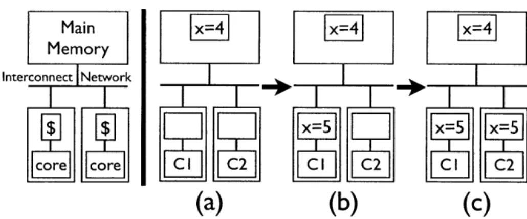
To deal with the high latencies involved in fetching data from memory, each core utilizes a small amount of high-speed memory, or cache. Since cores will want to work on the same data sets concurrently, the issue of keeping the caches coherent arises. If one core changes the value of a variable, the other cores will need to be notified of the change, lest they continue to use a stale copy. An example of two cores operating on the same data is shown is Figure 2-1.
While cache coherence is well understood for processors with small core counts, there remain a lot of questions regarding cache coherence in processors with more than a few dozen cores. Indeed, the viability of cache coherence in many-cores remains an open question [4]. This thesis aims to explore the viability of some common cache coherence schemes using simulated many-core architectures.
It is possible to provide a processor which does not maintain coherent caches, although other methods must be provided to allow multiple cores to operate on the same data set. One technique is to provide specialized user networks and messaging primitives to allow cores to directly communicate shared data. Another technique used by graphics processors is to maintain data coherence by flushing data to off-chip memory [15]. However, these programming models can be more difficult to use than a coherent shared memory model.
(a)
(b)
(c)
Figure 2-1: Example of the cache coherence issue, in which two cores are using the same variable X. (a) Neither core is caching the variable X. (b) Core 1 has requested to write 5 to the variable X, and now has X cached with exclusive permission to write X. (c) Core 2 has requested to read X. The cache coherence protocol must first demote Core 1's privileges for X to read-only, and then deliver the fresh value of X from Core 1's cache to Core 2's cache. Note that the caches exhibited here are write-back, which means that Main Memory can hold stale values, as seen in both (b) and (c).
In this chapter, some of the more common cache coherence protocols are discussed. Snoopy protocols are commonly used in small scale multi-core processors and are discussed in Section 2.1. Directory protocols, discussed in Section 2.2, are more scalable and will be the focus of this thesis. The full-map directory, described in Section 2.3, has great performance but poor memory scaling, and will serve as a good benchmark for the optimistic performance limits of directory-based protocols. Limited-map directory protocols can exhibit poor performance, depending on the user applications, but does not exhibit the memory scaling issue suffered by full-map directories, and are discussed in Section 2.4. A compromise between full-full-map and limited directories is the LimitLESS protocol, presented in Section 2.5. These protocols will be implemented and explored further in Chapter 4. Additional protocols are discussed in Sections 2.6 and 2.7, but are not implemented and benchmarked for this thesis.
The following notation will be used to describe most of the cache coherence schemes studied in this thesis: DirgX
[2].
i describes the maximum number of sharers allowed at any given time per memory line. X can either be B for a protocol which broadcasts invalidates to all cores, or NB for a protocol that only send messages tothe cores that are sharing the data. n will refer to the total number of cores in the processor such that DirnX refers to a protocol which allows all n cores to share any given memory line simultaneously.
2.1
Snoopy Protocol
The most popular method used to maintain cache coherency is to have all caches listen to a single memory bus [9]. Due to the broadcast nature of busses, all caches connected to the bus can monitor all communications on it. If a cache notices that a shared variable it holds has been modified by another cache, it will invalidate its copy of the variable. This protocol is known as a snoopy cache, because each cache snoops on the bus listening for any changes that occur. It can be referred to as a DirnB protocol, as all cores are allowed to share a given memory line simultaneously and the actions of invalidations are broadcast to all cores connected to the bus. Snoopy caches are fast; however, they do not scale well past more than a few dozen cores. It becomes infeasible to attach every core to a single memory bus, and it becomes prohibitively expensive to broadcast messages across the entire network to every cache [9]. For this reason, the snoopy protocol will not be explored in this thesis.
2.2
Directory Protocols
Directory caches try to solve the scalability problem found in broadcast protocols such as snoopy caches: instead of broadcasting every cache coherency action to all caches - which is expensive and time-consuming - directory caches only send cache coherency messages to the caches that are sharing the data. Directory protocols of this nature can be referred to as DirNB protocols, as they only broadcast invalidation messages to the relevant cores. However, directory based caches suffer two problems. Directory caches must maintain - for each piece of data - a list of all caches that hold a copy of the memory block. Thus, a fully mapped directory (DirnNB) for a thousand core processor must keep track of 1000 bits. Second, directory caches require more
overhead to handle cache coherency actions. A cache write will first involve a message of intention to the directory; the directory must notify all of the caches which share the memory block to invalidate their copy of the shared datum; once the directory has received acknowledgements back, it can then notify the writing cache that it is free to proceed with the action. Despite these two disadvantages, directory caches maintain an enormous advantage over snoopy caches: scalability. Therefore, directory caches have remained an intense focus of research as they are expected to perform better as processors scale to hundreds of cores [20, 9].
2.3
Full-Map Directory Protocol
The full-map directory scheme (DirnNB) is a directory protocol in which all cores in the processor can share a given piece of data simultaneously. Full-map directories have relatively good performance, however, they suffer the drawback of having to maintain an enormous amount of state [9, 10}. In particular, each block in memory must maintain a complete list of all caches in the system. The amount of data required to store the state of the memory block scales linearly with the number of processor cores; for a thousand-core processor, a thousand bits must exist for each data block [20, 9]. A number of variations to the full-map directory-based scheme exist that attempt to reduce the amount of state that must be stored, while attempting to maintain the low latency that is enjoyed by the cache coherency messages [20, 9, 10].
Despite the memory utilization drawback, the full-map directory will be used in this thesis to serve as an upper bound on directory protocol performance in Chapter 4.
2.4
Limited-Map Directory Protocol
Limited directory schemes (Dir4NB) attempt to alleviate the issue of storing too many cache pointers by storing only a bounded list of pointers to caches (where i pointers is less than n cores in the system). If a new cache wishes to read a shared data
(a)
(b)
(c)
(d)
(e)
(f)
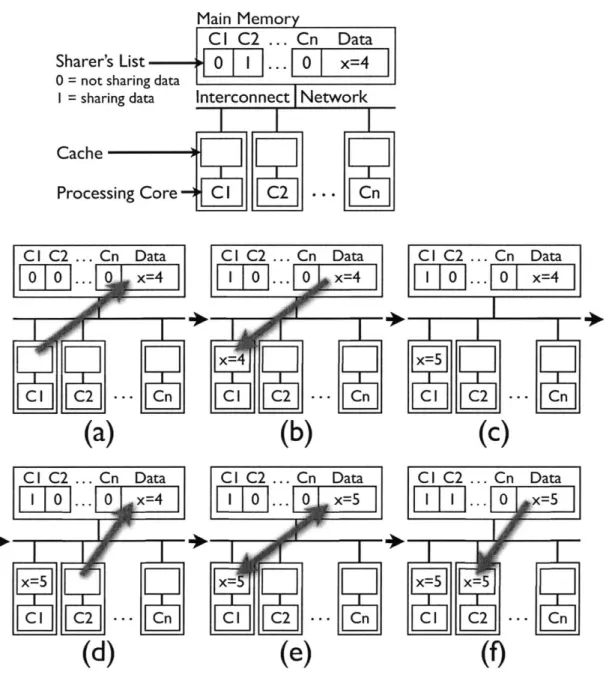
Figure 2-2: An example of two cores sharing the same data line X in a full-map directory system. (A) Core 1 requests the data X from the DRAM directory. (B) The directory sends the data to Core 1 who caches it, and then (c) updates X to 5. (d) Core 2 then requests read permission to X. (e) First, the directory must demote Core 1 from the Exclusive state to the Shared state. In this example protocol, Core 1 also sends his fresh copy of X to update the directory's stale copy. Once complete, (f) the directory can send a fresh copy of X to Core 2, and both cores can continue sharing X with read privileges.
(a)
(b)
(c)
Hx
= 5x- X5-
(d)
(e)
(f)
Figure 2-3: An example of two cores utilizing the same data line X in a limited-map directory system, with support for one sharer (DiriNB). (A) Core 1 requests the data X from the DRAM directory. (B) The directory sends the data to Core 1 who caches it, and then (c) updates X to 5. (d) Core 2 then requests read permission to X. (e) Because in a DirINB protocol the directory can only support one sharer at a time, the directory must evict Core 1 from the sharer's list, invalidate Core 1's copy of X, and process the write-back of Core 1's dirty copy of X. Once complete, (f) the directory can send a fresh copy of X to Core 2.
block, and the pointer list is full, one of the pointers is evicted and the appropriate memory block invalidated to make room for the new cache pointer. The drawback is that if more caches than available pointers continuously access the same shared data, the directory will thrash as it repeatedly evicts and then adds caches [20]. Memory usage in limited directories scale with the log(n) of the core count, and are thus more scalable than full-map directories. However, the software must be very aware of the underlying limitations to avoid thrashing the memory system. Effects of this thrashing can be seen in Chapter 4.
2.5
LimitLESS Protocol
Not all cache coherency strategies need to rely solely on hardware. Much of the hardware complexity and cost can be eliminated by moving some of the functionality into software. The LimitLESS directory (Limited Directory Locally Extended thru Software Support) is similar to the limited directory, but instead relies on software to maintain a list of pointers to caches if the hardware list is full. Therefore, LimitLESS directories do not exhibit the same thrashing seen in limited directories due to heavily shared read-only data. The LimitLESS directory maintains the memory overhead of a limited directory, but attempts to gain the advantages of a full-map directory by storing the additional cache pointers in software [10].
LimitLESS protocols will be abbreviated as LimitLESS(i), where i is the number of supported hardware pointers. For example, if i sharers have cached a particular memory address, future sharers will have to trap into software in order to be added to the sharer's list. This protocol is explored in Chapter 4.
2.6
Chained Directory Protocol
A chained directory is a variation of the limited directory, but instead of maintaining a fixed number of pointers, a chained directory scheme maintains an extendable list of pointers. The last pointer in the directory points to a cache. This last cache
contains a single pointer to another cache that shares the datum. In turn, one can imagine each cache pointing to the next cache that also shares the memory block in question. This approach can add considerable latency to cache operations. If a cache wants to write a variable, it must contact the directory and then crawl to every cache, invalidating each cache's variable one at a time. Only once this has happened can the writing cache complete the write action. However, it addresses the problem found in limited directories that can occur when too many caches need to access the same data [20]. Chained directories differ significantly from the standard DirNB protocols in functional implementation, and thus, evaluating the Dir4NB protocols discussed in Sections 2.3, 2.4, and 2.5 were given higher priority. However, chained directories are an intriguing scheme that warrants additional investigation.
2.7
Other Strategies
Another strategy to maintaining cache coherency, which avoids much of the headache inherent in most cache coherency schemes, is to impose exclusivity on cached data [20]. While local data and shared read-only data can be spread amongst the cores, any data that are shared-write are not allowed to reside in multiple caches. This effectively side-steps much of the difficulties involved in communicating coherency issues that arise from writing to shared data. Unfortunately, the software must ex-plicitly mark all variables as either cacheable or non-cacheable. While a private-only cache scheme is not an optimal strategy, it is simple and does not require complex hardware [20]. Because of these reasons, it is a very appealing approach for chip de-signers, particularly if the processor platform provides the programmer other, faster communication models for sharing data, such as explicit messaging. This thesis aims to explore the issues in providing high-performance cache coherence and thus will avoid these other solutions to data sharing.
Chapter 3
The Graphite Simulator
Simulators play an important role in exploring architectural designs. Where the alternative is to push a single, highly detailed design to fabrication, simulators allow designers and researchers an opportunity to quickly model a particular aspect of a processor and then iterate many different alternative implementations in a relatively short amount of time. In this regard, simulators are the ideal platform for exploring cache coherence in many-core processors.
However, because current simulators are insufficient for studying many-core archi-tectures, a new simulator, called Graphite, was implemented. Graphite is a modular simulator that allows researchers to modify components to explore different target architectures. For this thesis, Graphite will be targeting a homogenous many-core processor with simple, in-order cores connected through a 2-dimensional mesh inter-connect network.
Section 3.1 will explore in more detail the motivation for creating Graphite. Sec-tion 3.2 will describe the features of Graphite that make it well suited for cache coherence studies. Section 3.3 discusses the details of the processing core simulated in this thesis. Section 3.4 discusses the design and implementation of the shared memory system, where a significant part of the engineering effort of this thesis was spent. Section 3.5 discusses the interconnection network used for modeling commu-nications between the cores. Additional information on Graphite can be found in J. Miller, et. al. [18].
3.1
The Motivation for a New Simulator
There exist many simulators and emulators that allow for the study of novel target architectures, such as SimpleScalar [5], Simics [17], ASim [14], and FAST [11]. Many of these simulators are capable of modeling small-scale multi-core processors, however, they are aimed at targeting few-core processors and run on sequential machines. Therefore, these simulators are not up to the task of exploring cache coherence in many-core processors.
3.2
Graphite Simulator Features
The Graphite simulator aims to allow the research of many-core architectures. It accomplishes this goal through the following features:
" simulate user applications distributed across a cluster of commodity hardware " relaxed synchronization between target components
" provide a single, coherent shared memory space to the user application " direct execution of user application code on the host architecture " run off the shelf, unmodified, threaded source code
Because of these features it is possible to run regular, POSIX threaded benchmark applications targeting 1000-core processors with a slow-down over native run times of on average 3250x from the SPLASH benchmarks[18]. Thus, Graphite is a perfect simulator for studying cache coherence in many-core processors.
3.3
The Processing Core
As mentioned in Chapter 1, this thesis assumes that future processors will choose higher numbers of smaller, simpler cores over fewer, but more powerful cores. Thus the processing cores simulated under Graphite are simple, in-order, single-issue cores. All
cores are homogeneous. Each core has its own, local Li instruction and data caches, as well as a local L2 data cache. The cores model a store buffer and are capable of servicing multiple outstanding memory requests. A simple, one-bit branch-predictor is also provided.
3.4
The Shared Memory System
In studying cache coherence, it is necessary to know when the user application touches memory so that the correct behavior in the memory system can be modeled. This can be accomplished by monitoring memory loads and memory stores. Therefore, to simulate an entire memory system, Graphite runs a user application natively on the host hardware and then, during execution of the user application, inserts additional code around loads and stores. This additional code insertion, or instrumentation, then executes Graphite's shared memory system. The memory system can then model the accesses appropriately. Actions the memory system may take involve checking the cache for a hit, requesting the data from the directory, fetching the data from DRAM, invalidating sharers, and performing writebacks on evicted cache lines.
The instrumentation tool, or dynamic binary translator, not only instruments loads and stores, it also models the costs of all instructions executed on the processor. For this thesis, Pin [16] was used, although it would be possible to run Graphite using a different instrumentation tool such as QEMU [6].
A significant portion of the engineering effort of this thesis went into the design and development of shared memory system used by Graphite. Section 3.4.1 will discuss the memory hierarchy used in Graphite as well as what happens when a load or store is instrumented by Pin. Section 3.4.2 discusses the implementation of the directories used in keeping the caches coherent. Section 3.4.3 discusses the different cache coherence protocols implemented for Graphite.
3.4.1 Caches
In Graphite, every core is provided its own Li instruction and data caches, and its own local L2 data cache. For this thesis, caches are not shared. The Li cache is write-through, and thus is kept coherent with the L2 cache. The L2 cache is the last-level cache, and is kept coherent through a cache coherence protocol described in Section 3.4.3.
When a memory operation traps into the shared memory system, the core's cache is checked to verify that the data resides in the cache and that the cache has the correct privileges to continue with the operation. Any given cache line can have three possible states as described in Table 3.1
Table 3.1: Possible Cache States Uncached cache line is currently unused
Shared read-only permissions Exclusive write & read permissions
When data is in the Shared state, it is possible that other caches may also have a copy of the data. Therefore, the only allowed operation on the data is a Read operation. If a core desires to perform a Write operation, it must have exclusive access to the data. Thus, the core only has write privileges if the cache-line is in the Exclusive state.
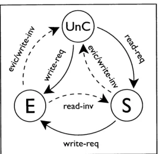
This protocol is known as the MSI protocol' and is described in Figure 3-1. If the core does not have the data in its cache or the core does not have sufficient privileges to act on the data, the memory manager sends a message over the intercon-nect network to contact the directory. The directory, after performing any necessary invalidations as described in Chapter 2, then sends the data to the requesting cache at which point execution can then continue.
1MSI stands for Modified, Shared, Invalid. A stylistic decision was made to refer to the Modified
write-req
Figure 3-1: A memory-line in the cache can be in one of three states: Uncached (Unc), Shared (S), or Exclusive (E). A cache-line that is unused is in the Uncached state. Data that has read-only privileges and could be shared by any number of caches is in the Shared state. Data with write and read privileges, which cannot be simultaneously stored in any other caches, is in the Exclusive state. Solid arrows describe actions taken by the core, either a read-request or write-request. Hatched arrows describe actions taken externally, either commands sent from the DRAM di-rectory - another core requests write access (write-inv) or another core requests read access (read-inv) - or the external action could be a cache eviction (evic).
3.4.2
Directories
The directory, as described in Chapter 2, Section 2.2, plays an important role in cache coherence, as it keeps track of which cores are presently using data. Any core that needs data must first contact the directory, as described in Section 3.4.1.
Each memory line in the DRAM can have one of the following states, as described in Table 3.2.
Table 3.2: Possible DRAM States
Uncached memory-line is not cached
Shared At least 1 cache has read-only permissions. Exclusive 1 cache has write & read permissions.
Figure 3-2: A memory-line in the DRAM can be in one of three states: Uncached (Unc), Shared (S), or Exclusive (E). Data that is not stored in any caches is in the Uncached state. Data that is being shared by any number of caches, in which all caches have read-only privileges, is in the Shared state. Data in the Exclusive state can be stored by only a single cache, which has write and read privileges.
However, the execution of a parallel application can quickly become serialized if a lot of cores swamp the directory with requests. Thus, the implementation details of the directory can have a dramatic effect on the scalability of the processor.
Therefore, it is important to distribute the directory. By breaking the directory into smaller pieces, it is possible to better accommodate high memory traffic. Each piece of the directory is placed in charge of a piece of the memory space.
The issue of directories and their distribution raises many interesting research topics. How many directories should exist for a given core count? How should the memory space be distributed across the directories? Where should the directories be located? These topics, however, are beyond the scope of this thesis. Instead, these parameters will be taken as given. Graphite has as many directories as there are cores in the target processor. The memory space will be striped in 256 byte sections and distributed evenly to all directories. The directories will be distributed across the entire processor with each directory sharing a network node with a core.
Each DRAM directory has direct access to off-chip DRAM. Off-chip memory ac-cesses are given a constant latency of 237 cycles. Future work will add an analytical queuing model which measures access latency as a function of access contention and available bandwidth.
3.4.3
Cache Coherence Protocols
One of the greatest implementation challenges of Graphite was the distribution of the simulator across a cluster of computers while maintaining a fully cache coherent, shared memory view to the user application. This means that the cache coherence used by the simulator is not only important for performance modeling, it is also crucial for the functional execution of the simulator.
Three different cache coherency schemes were implemented in Graphite: full-map directories, limited directories, and LimitLESS directories. These protocols are described in detail in Chapter 2.
Limited directories are the base-line directory scheme in Graphite. In implement-ing limited directories, the directory tracks the number of current sharers for every memory line. If an additional core requests to be added as a sharer, but the memory line already has the maximum supported sharers, a sharer is picked at random and evicted. Limited directories can be configured by setting the number of supported
sharers per memory line.
To model full-map directories using Graphite, one only needs to set the maxi-mum number of sharers equal to or greater than the number of cores in the target architecture.
LimitLESS directories are functionally identical to full-map directories. Two mod-ification are needed to the full-map protocol to simulate the costs of the LimitLESS protocol. The first modification is an additional check when adding a sharer to the sharers lists.
In configuring LimitLESS directories (denoted as LimitLESS(i)), the number of hardware-supported sharers is set at some value i. This is the number of sharers that can be added to a memory line's sharer's list without issuing a software trap. The second modification to the full-map directory implementation is an additional check when invalidating the caches in the sharer's list. If k caches are on the sharer's list, (k - i) caches must be invalidated in software.
While it could be possible to functionally perform the software trap, Graphite instead only simulates a constant cost that is added to the relevant core's clock. This is inline with the technique used to model LimitLESS directories in Chaiken, et. al. [8]. The LimitLESS protocol code used can be found in Appendix A.
3.5
Interconnect Network
The modular nature of Graphite allows for researchers to plug in their own modules. This ability extends to the network module, where users can study ring networks, hypercubes, all-to-all interconnects, busses, and more.
For this study, Graphite is using a 2D mesh interconnect. Messages are directly sent to the receiving node, however, message latency is modeled based on the num-ber of hops required to route a message between the sending and receiving nodes. Contention is not currently modeled, however, future implementations will utilize an analytical network contention model.
Chapter 4
Experiment Methodologies and
Results
The following chapter investigates the viability of different cache coherence strate-gies using the Graphite simulator. For this study, the applications blackscholes and 2D Jacobi were used. Section 4.1 describes the experimental setup and the tar-get architecture that is being simulated. Section 4.2 describes the data concerning the application blackscholes , and Section 4.3 describes the results concerning the application 2D Jacobi. These sections are further broken into subsections that de-scribe the application's characteristics and the specific parameters used in obtaining the results. It also presents the results of the experiments and discusses the implica-tions. Finally, Section 4.4 summarizes the results from the different applications and discusses the viability of the different coherency schemes in many-core processors.
4.1
Experimental Setup & Target Architecture
The simulated, or targeted, architecture is a many-core processor. All cores are ho-mogenous, in-order, and single-issue. Each core has its own Li cache, which writes-through to the L2 cache. The L2 cache is local to each core, however data in the L2 is kept coherent through a directory-based cache coherence protocol. The exact protocol is changed in each experiment. The penalty paid in software traps for the
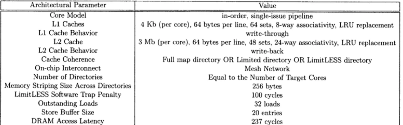
LimitLESS protocol is set to 100 cycles. This is inline with the penalties explored in Chaiken, et. al. [10], which compared latency penalties between 25 cycles to 150 cycles. Further target architecture parameters are described in Table 4.1.
The following simulations were run on commodity dual quad-core Intel 3.16GHz Xeon servers, running Linux version 2.6.18. Each machine has 8GB of RAM. All code was compiled 32-bit under gcc version 4.1.2.
Architectural Parameter Value
Core Model in-order, single-issue pipeline
Li Caches 4 Kb (per core), 64 bytes per line, 64 sets, 8-way associativity, LRU replacement
Li Cache Behavior write-through
L2 Cache 3 Mb (per core), 64 bytes per line, 48 sets, 24-way associativity, LRU replacement
L2 Cache Behavior write-back
Cache Coherence Full map directory OR Limited directory OR LimitLESS directory
On-chip Interconnect Mesh Network
Number of Directories Equal to the Number of Target Cores
Memory Striping Size Across Directories 256 bytes
LimitLESS Software Trap Penalty 100 cycles
Outstanding Loads 32 loads
Store Buffer Size 20 entries
DRAM Access Latency 237 cycles
Table 4.1: Target Architecture Parameters
4.2
Blackscholes
This section will explore the results of different cache coherence protocols on the target architecture described in Section 4.1 using the application blackscholes. Section 4.2.1 will describe blackscholes and its sharing behavior. Section 4.2.2 describes the experimental setup uses for running blackscholes. Section 4.2.3 shows the results from increasing the number of target cores, and discusses the relative performance of the full-map, limited, and LimitLESS directory schemes.
4.2.1
Application Characteristics
Blackscholes is an application from the PARSEC Benchmark Suite [7]. The PAR-SEC Benchmark Suite aims at providing computer architects applications capable of sufficiently representing future workloads that target highly parallel processors. Blackscholes is a highly parallel application used for calculating the market price
for financial derivatives, or "options". M "options" are statically allocated between N threads. Each "option" is calculated in complete isolation, and thus there is no inter-thread communication between worker inter-threads regarding the computation of "option" pricing. There is however significant read-sharing exhibited by blackscholes .
As described in the PARSEC paper by Biena, et. al. [7], blackscholes exhibits a little over 1 byte per instruction of private reads, 1 byte per instruction of private writes, and about half a byte per instruction of shared reads. Virtually no shared write traffic exists. As explained in [7], the sharing arises from the initialization of the options portfolio by the master thread, who then spawns the worker threads who read the data. Thus, this read data is accessed at most by two threads [7], each at different times of the application's execution.
However, in tracking memory accesses on a memory line granularity using Graphite, it was noticed that about two dozen memory lines were heavily read-shared amongst
all cores. These memory addresses were located in the system libraries. The ac-cesses nearly disappeared when the math. h functions exp (), sqrt (), and log() were commented out.
4.2.2
Experimental Setup
The results gathered from blackscholes were for simulations targeting the architec-ture described in Section 4.1. Blackscholes was compiled under -02 optimizations. The simsmall input set was used for these simulations, in which 4096 options are statically divided up by N target cores. The blackscholes application then calcu-lates each option 100 times to inflate the workload performed. In a target processor with 128 target cores, each core is responsible for 32 options, each which is then cal-culated 100 times. For a 128 target core processor, the final work load per core is 3,200 options.
Blackscholes is run using the following cache coherent schemes: full-map (DirnNB), limited (Dir4NB and Dir1 6NB), and LimitLESS(4) directories. The details of these
protocols are described in Chapter 2.
128 64 32 16 8 4 2 0.5 0.25 0.125 0.0625 0.0312 0.0156 0.0078 0.0039 0.002 1 64 128 256
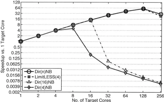
Figure 4-1: Different cache coherency schemes are compared using speedup relative to simulated single-core execution in blackscholes by scaling target core count. speedup, for each protocol, blackscholes is run on a target processor with a given number of cores. The number of target cores is then increased from 1 core to 256 cores. The simulated cycle time from each run is then divided by the simulated cycle time of the 1 core run, and inverted, to provide a measure of speedup:
SpeedupN = CyCleSlCyCleSN
Once the speedup has been calculated, the performance of the different cache coherence schemes can be compared.
4.2.3
Comparison of Different Cache Coherence Protocols
Figure 4-1 shows the comparison of the full-map, limited, and LimitLESS directory schemes.As blackscholes exhibits near perfect parallelism, it is not surprising to see excellent scaling of the full-map protocol from 1 to 128 cores. However, 256 cores
2 4 8 16 32
No. of Target Cores
I I I I I I II
--
DrnN ---- -- - ---.--... ... .. ...---...-. .. .--9- Dir(n)NB~ -+-Dir(4)NB-'..
.
...
I
... ...
...
exhibits a less than perfect speedup. This is may be due to the course grain parallelism and static distribution of the workload exhibited by blackscholes . However, though this dataset was collected using the simsmall input, identical trends have been noted with the simmedium input as well, which exercises 4x the number of options found in the simsmall input. Future many-core threading libraries may be interested in utilizing more efficient thread creation methods, such as a spawning tree, to decrease the execution time wasted in spawning hundreds of threads sequentially.
Limited directories do not scale due to the repeated read-sharing exhibited in blackscholes. Once the number of target cores exceeds the number of supported sharers, heavy thrashing in the caches results. As more target cores are added to the processor, the execution effectively becomes serialized on a few, heavily shared memory lines.
The full-map and LimitLESS directories perform nearly identically. This is not surprising as there is nearly no shared write data. Therefore, once LimitLESS direc-tories have cached the read data, it will behave exactly like a full-map directory.
4.3
2D Jacobi
This section will explore the results of different cache coherence protocols on the target architecture described in Section 4.1 using the application 2D Jacobi . Sub-section 4.3.1 will describe the 2D Jacobi and its sharing behavior. SubSub-section 4.3.2 describes the experimental setup uses for running 2D Jacobi . Subsection 4.3.3 shows the results from increasing the number of target cores, and discusses the relative per-formance of the full-map, limited, and LimitLESS directory schemes.
4.3.1
Application Characteristics
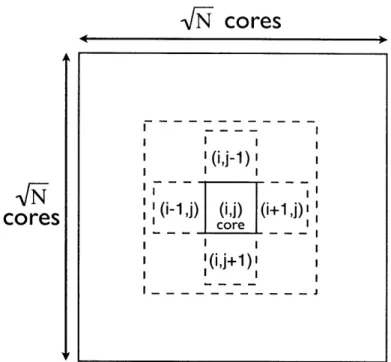
2D Jacobi iteratively relaxes a 2D matrix by averaging each element's four neigh-bors (north, south, east, and west) at each time step. As shown in Figure 4-2 the application exhibits a common sharing pattern of nearest-neighbors sharing. At every time step, each element in the matrix is recomputed by averaging the element's four
VN
cores
-- - -- - - - - I '(i,j-1) cores core (i (i,j+1) - ---Figure 4-2: Partitioning of a 2D matrix between N threads in 2D Jacobi. Shown is a single core at location (i,
j).
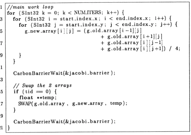
It's four neighboring cores are shown at the four compass points. Each core is the only writer for the elements inside its domain, but it must read-share the data at its boundaries. Thus data is shared in a nearest neighbors fashion.neighbors. The new value is written to a second matrix to prevent overwriting values from the current time-step. Once finished, all threads barrier to prevent threads from running ahead. The code for this algorithm is shown in Figure 4-3.
A 2D square matrix is divided between N cores. These sections will be referred to as blocks, and each core is in charge of computing the values inside its block. Thus only a single core writes to any given element in the matrix, however, sharing occurs at the boundaries of the blocks. Therefore, we expect that most of the read-data used in 2D Jacobi will be shared between at most four cores. The data read at the boundaries of the blocks will be updated by one core, which means that invalidations of the shared data will occur at every time-step.
This implementation of 2D Jacobi utilizes two matrixes. At time-step i, data is read from matrix A and the updated values are written to matrix B. The pointers to matrix A and matrix B are then switched by core 0 at the end of the time-step. This code is detailed in Figure 4-3. The ramifications of having a single core update
1 //main work loop
for (Sint32 k = 0; k < INUMUERS; k++1){
3 for (Slnt32 i = start-index.x; i < end-index-x; i++)
{
for (SInt32j
= startindex-y;j
< cnd-index~y;j++) {
5 g-newarray[i-jJ = (gold-array(i-1]j]
+ g~old -arr ay [i- a 1]}
7 + g-old-arr ay [ i j -l* + g-old-array[ i j -1]) / 4; 9 }
}
11 CarbonBarrierWait(&jacobi .barrier); 13// Swap the 2 arrays
15 if (tid == 0) { float **temp;
17 SWAP( g.old-array , g-new-array , temp);
}
19
CarbonBarrierWait(&j acobi -barrier); 21
}
Figure 4-3: The main loop in 2D Jacobi is shown. Each worker thread executes the above loop. At each time-step, a new value is computed for each element by averaging the element's neighboring values. These values are read from g..old-array and the new value is written to g-new-array prevent overwriting the current values. Once each thread is finished computing the new array for the given time-step, all threads wait at a barrier. Core 0 then swaps the pointers of the two matrices, and then the next time-step begins.
the matrix pointers is discussed below in Section 4.3.3.
Finally, the barrier variable used in this implementation of 2D Jacobi is shared between all cores.
4.3.2
Experimental Setup
2D Jacobi was run with an input matrix of dimensions 504x504, for a total of 254,016 elements. These elements are statically allocated between N cores. Due to how the matrix is partitioned, N must be a perfect square. This limits the number of available target architectures that could be explored. The number of target cores explored range from 1 core to 144 cores. For each coherence scheme studied, the speedup for
128 64 --- -32 16 - -- . . - - - -.. .-- ---. . .. . . . .--. --.. - - ---. . ---. - -... . . . .. . . .... -- --- ---..-- ---. .- --- -0 a) 0.5 - - -- -- - -- --... - - - -....- - - - -0.0625 - -.Dir()NB... a.08)4 Dir(1)NB 1 4 9 16 36 81 144
No. of Target Cores
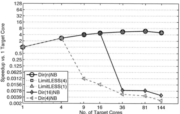
Figure 4-4: Different cache coherency schemes are compared using speedup relative to simulated single-core execution in 2D Jacobi by scaling target core count.
each target core number is collected. The cache coherence schemes explored are full-map (DirNNB), limited-full-map (Dir4NB and Dir1 6NB), and LimitLESS (LimitLESS(1)
and LimitLESS (4)) directories. As the maximum amount of sharers per data element is expected to be 4, a significant performance difference is expected to exist between LimitLESS(1) and LimitLESS (4). The target architecture parameters are the same as described in Table 4.1. 2D Jacobi was compiled using -00 optimizations.
4.3.3
Comparison of Different Cache Coherence Protocols
As seen in Figure 4-4, full-map and LimitLESS directories exhibit little speedup over single-core target execution, as the performance appears to quickly level off after nine cores. This is puzzling for an algorithm in which each element of the matrix possesses only a single writer. Certainly, we expect some invalidations to occur of the shared data at the boundaries of each block, but results this dramatic suggest a performance bug.
macro is the culprit of the poor scaling witnessed in full-map and LimitLESS direc-tories. The matrix pointers are heavily shared by all cores for calculating the address offsets needed to find the relevant elements in the matrices. DirNNB protocols should not have a problem with heavy sharing of read-data, but the SWAP performed by core 0 invalidates all of the cores that had cached the matrix pointers. Thus every time-step all of the cores swamp the single directory storing the two matrix pointers.
Limited directories also exhibit equally interesting results. 2D Jacobi utilizes nearest neighbor sharing paradigm (a single writer, with four readers) that would appear to be supportive of limited directories. However, the results displayed in Figure 4-4 show that limited directories perform dismally once the number of supported hardware sharers is less than the number of target cores in the processor.
Further analysis of the the assembly generated by gcc with -00 optimizations revealed that the matrix pointers used in calculating address offsets is never stored in the register file. Address offsets are calculated four times for the read data and once again for the write destination. In Dir4NB, only 4 sharers are allowed to cache these
matrix pointers. Yet all cores in the target processor, five times for every element in the matrix, are trying to read the matrix pointers. The entire application becomes serialized on the access of this data.
There also may be some contribution due to the barrier implementation utilized at the end of each time-step. All cores are accessing the same, global barrier, which would be expected to cause further thrashing for limited directories.
The performance of LimitLESS directories is almost identical to that of the full-map directories. There is significant memory traffic occurring for both full-full-map and LimitLESS directories and thus it is expected that noticeable differences would arise. While the software trap penalties were chosen to be comparable with the penal-ties studied in Chaiken, et. al., [10], it is possible that other latencies exhibited by Graphite may not be tuned to provide enough accuracy to discern full-map and LimitLESS protocols for this particular data-set.
A re-write of 2D Jacobi which eliminates all of the unnecessary memory hotspots could allow for better scaling to be witnessed by all protocols. First, the global matrix
pointers should be copied by all cores and stored in their respective register files. Second, each core will need to perform the SWAP operation on their own copy of the matrix pointers. This has two effects: elimination of the producer-consumer pattern currently exhibited when Core 0 performs the SWAP, and allowance for the removal of the second barrier in the main loop.
4.4
Discussion
The applications studied in Section 4.2 and Section 4.3 follow common parallel pro-gramming paradigms and are expected to be highly scalable. Blackscholes cleanly divides all work and exhibits no sharing of the options data between the worker threads. The only relevant sharing occurs in the system libraries. 2D Jacobi utilizes the nearest neighbors paradigm to partition a 2D matrix amongst the cores. Writing is kept private, and the only sharing occurs at the boundaries between each core's block in the matrix. This boundary sharing is entirely read-only. Also, no more than four cores should be sharing any given element in the matrix. Additional sharing was accidently introduced through the address offset calculations from the matrix pointers and through the barriers.
Because blackscholes only exhibit read sharing, we see good performance from the full-map directory protocol. Once the data is cached, there are no invalidations from either shared writes or conflict misses in the cache. 2D Jacobi exhibits much poorer performance due to the writing of the matrix pointers by core 0 at every time-step, akin to a producer-consumer sharing paradigm. There is little to no benefit over using 144 cores when compared to using 36 cores. However, because the full-map directories do not suffer from the thrashing caused by heavily shared read-data, the full-map protocol exhibits the best performance that can be expected.
Likewise, the LimitLESS protocol yields nearly identical performance with the full-map directory. The LimitLESS protocol is penalized with software traps when too many sharers exist for a given memory address. However, if no shared writes or conflict misses occur, the data stays cached. If the memory requests are infrequent,
LimitLESS directories can avoid the software overhead and thus stay competitive with full-map directories.
The limited map directories performed surprisingly poorly. Blackscholes ex-hibits no sharing of the option data, as each option is calculated in isolation. Like-wise, the 2D Jacobi algorithm dictates that each core shares data with at most four nearest neighbors. Thus the algorithms used in both applications suggest excellent performance with limited map directories. However, blackscholes suffers from the implementation of the math functions it relies on for its calculations. 2D Jacobi suffers from subtle performance bugs due to the implementation of matrix address calculations and the implementation of the barrier routine. These results serve as an excellent example of the surprisingly bad performance that can be elicited from lim-ited directories. The application developer must be very careful to not introduce any data that might be heavily shared by more cores than are supported by the limited directory. Worse, the application developer must also be fully aware of the sharing patterns exhibited by the libraries he uses.
Although it is hard to draw definitive conclusions from the limited applications used in this study, it is clear that evictions due to allowing only a limited number of sharers can cause unreasonable performance. Any cache coherence schemes used in many-core processors will have to support massively shared read data. Even allowing for only a small number of memory addresses to be shared by all cores may be enough to match the performance exhibited by the full-map directories.
Full-map directories are not viable due to the memory requirements in tracking all possible sharers for every memory line. Instead, computer architects will have to utilize schemes that attempt to achieve the performance of full-map directories with the memory utilization of limited directories. LimitLESS directories are one promising possibility.