Publisher’s version / Version de l'éditeur: PERD/CHC Report 11-20, 1998-05-31
READ THESE TERMS AND CONDITIONS CAREFULLY BEFORE USING THIS WEBSITE. https://nrc-publications.canada.ca/eng/copyright
Vous avez des questions? Nous pouvons vous aider. Pour communiquer directement avec un auteur, consultez la
première page de la revue dans laquelle son article a été publié afin de trouver ses coordonnées. Si vous n’arrivez pas à les repérer, communiquez avec nous à [email protected].
Questions? Contact the NRC Publications Archive team at
[email protected]. If you wish to email the authors directly, please see the first page of the publication for their contact information.
NRC Publications Archive
Archives des publications du CNRC
For the publisher’s version, please access the DOI link below./ Pour consulter la version de l’éditeur, utilisez le lien DOI ci-dessous.
https://doi.org/10.4224/12328412
Access and use of this website and the material on it are subject to the Terms and Conditions set forth at
Comparison of International Codes for Ice Loads on Offshore
Structures
Tseng, J.; with, Sandwell
https://publications-cnrc.canada.ca/fra/droits
L’accès à ce site Web et l’utilisation de son contenu sont assujettis aux conditions présentées dans le site LISEZ CES CONDITIONS ATTENTIVEMENT AVANT D’UTILISER CE SITE WEB.
NRC Publications Record / Notice d'Archives des publications de CNRC: https://nrc-publications.canada.ca/eng/view/object/?id=43788f13-fb30-4cba-95ab-0dd791323e39 https://publications-cnrc.canada.ca/fra/voir/objet/?id=43788f13-fb30-4cba-95ab-0dd791323e39
National Research Council of Canada
Ottawa, Ontario
Comparison of International Codes for
Ice Loads on Offshore Structures
PERD/CHC Report 11-20
Project 142211 31 May 1998
Prepared by:
Sandwell Engineering Inc. Vancouver, Canada
Central Marine Research & Design Institute St. Petersburg, Russia
IMPORTANT
This document is for the private information and benefit only of the client for whom it was prepared and for the
particular purpose previously advised to Sandwell Engineering Inc. ["Sandwell"]. The contents of this document are
not to be relied upon or used, in whole or in part, by or for the benefit of others without prior adaptation and
specific written verification by Sandwell.
Particular financial and other projections and analysis contained herein, to the extent they are based upon assumptions concerning future events and circumstances over which Sandwell has no control, are by their nature uncertain and are to be treated accordingly. Sandwell makes no warranties regarding such projections and analysis.
Sandwell and its corporate affiliates and subsidiaries and their respective officers, directors, employees and agents assume no responsibility for reliance upon this document or any of its contents by any party other than Sandwell’s client.
Table of Contents
1.0 Introduction_______________________________________________________________ 4
1.1 BACKGROUND_______________________________________________________________ 4 1.2 OBJECTIVE__________________________________________________________________ 5 1.3 SCOPE OF WORK ____________________________________________________________ 5
2.0 Structural Design Approach __________________________________________________ 7
2.1 CSA_________________________________________________________________________ 7 2.1.1 Objectives ________________________________________________________________________ 8 2.1.2 Loads and Load Combination_________________________________________________________ 9 2.1.3 Method _________________________________________________________________________ 10
2.2 API_________________________________________________________________________ 10 2.2.1 Objectives _______________________________________________________________________ 12 2.2.2 Loads and Load Combinations _______________________________________________________ 12 2.2.3 Method _________________________________________________________________________ 13
2.3 SNIP And vsn_______________________________________________________________ 14 2.3.1 Objectives _______________________________________________________________________ 15 2.3.2 Loads and Load Combination________________________________________________________ 15 2.3.3 Method _________________________________________________________________________ 17
2.4 Summary Comparison_______________________________________________________ 18
3.0 Ice Design Approach_______________________________________________________ 20
3.1 CSA ________________________________________________________________________ 20 3.1.1 Ice Features______________________________________________________________________ 20 3.1.2 Structure Types___________________________________________________________________ 21 3.1.3 Ice Loads _______________________________________________________________________ 22 3.2 API_________________________________________________________________________ 23 3.2.1 Ice Features______________________________________________________________________ 23 3.2.2 Structure Types___________________________________________________________________ 24 3.2.3 Ice Loads _______________________________________________________________________ 25 3.3 snIp and VSN _______________________________________________________________ 26 3.3.1 Ice Features______________________________________________________________________ 26 3.3.2 Structure Types___________________________________________________________________ 27 3.3.3 Ice Loads _______________________________________________________________________ 27
3.4 Summary comparison of the code provisions for ice design____________________ 28
4.0 Ice Load Calculations ______________________________________________________ 30
4.1 Scenario 1 – Level Sheet Ice _________________________________________________ 30 4.1.1 CSA ___________________________________________________________________________ 30 4.1.2 API ____________________________________________________________________________ 33 4.1.3 SNiP and VSN ___________________________________________________________________ 34 4.1.4 Comparison for Scenario 1 __________________________________________________________ 36
4.2 Scenario 2 – First Year Ridge_________________________________________________ 38 4.2.1 CSA ___________________________________________________________________________ 38 4.2.2 API ____________________________________________________________________________ 40 4.2.3 SNiP and VSN ___________________________________________________________________ 41
4.2.4 Comparison for Scenario 2 __________________________________________________________ 42
4.3 Scenario 3 – pack ice of partial coverage______________________________________ 44 4.3.1 CSA ___________________________________________________________________________ 44 4.3.2 API ____________________________________________________________________________ 44 4.3.3 SNiP and VSN ___________________________________________________________________ 44 4.3.4 Comparison for Scenario 3 __________________________________________________________ 46
4.4 Summary comparison of ice load calculations_________________________________ 47 4.5 Commentary on Code Use and the Differences in the Codes __________________________ 49
5.0 Summary and Conclusions __________________________________________________ 51
5.1 Structure Design approach___________________________________________________ 51 5.2 Ice Design Approach ________________________________________________________ 51 5.3 Ice Load Calculations________________________________________________________ 51 5.4 Closure_____________________________________________________________________ 52
1
1
.
.
0
0
I
I
n
n
t
t
r
r
o
o
d
d
u
u
c
c
t
t
i
i
o
o
n
n
1
1.
.1
1
BA
B
AC
CK
KG
GR
RO
OU
UN
ND
D
Over the last three decades, oil and gas development activities in arctic and subarctic waters in many parts of the world have prompted designs of ice resistant offshore platforms. The understanding of ice mechanics, ice loads and structural reaction to ice action have made substantial advancement over the years, with the ultimate objective of rationalizing safe and economic ice resistant offshore structures.
In Canada, a number of offshore structures have been designed, fabricated and deployed in the Beaufort Sea and off the East Coast. The gravity-based platforms deployed in the Beaufort Sea in the early 1980’s were designed and constructed without the benefit of a Canadian design code for offshore structures. In view of this, the Canadian Standards Association (CSA) was asked by the federal government and industry to develop a code for the design, construction and installation of fixed offshore oil and gas production structures. In response to this request, CSA prepared draft standards and oversaw the verification of these standards. The verification process achieved a number of principal objectives:
• To verify that the code allows the designer to produce acceptably safe and reliable structure designs;
• To ensure that designers have confidence in the structures designed to the code;
• To ensure that practicing engineers can apply the code with reasonable ease and without ambiguity;
• To allow the practicing engineering community to become familiar with the provisions of the new code.
Some fifteen code verification projects, each focusing on specific portions of the code such as ice load, earthquake load, steel design, concrete design and composite design, were completed between 1987 and 1989. These verification studies led to recommendations for further code editing, culminating in the publication of the CSA Standard for Fixed Offshore Structure in 1992. The CSA code, in parallel with the Russian SNiP and VSN codes, has been applied recently to the design of the first offshore platform in the Russian Sea of Okhotsk, offshore Sakhalin Island.
The American Petroleum Institute standards (the API RP series) have also undergone a verification process to produce a set of design guidelines based on the more modern Load Factor Resistance Design (LFRD) approach, an alternative to the traditional Working Stress Design (WSD) approach. At the same time, the section on ice loads was updated to reflect appropriately the recent advances in that discipline.
The current interests in the development of oil and gas reserves in the Canadian, American and Russian arctic and subarctic waters will continue to call for the design and construction of ice resistant offshore structures and the issue of code application will invariably arise. In view of this, the National Research Council of Canada (NRCC) has commissioned this study. It is considered that this work is very timely. In particular, by
documenting the similarities and differences between the North American and the Russian standards for ice loads on structures, the study report will be an important reference for upcoming offshore structures designed by joint ventures of western and Russian companies for installation in Russian ice infested waters.
1
1.
.2
2
OB
O
BJ
JE
EC
CT
TI
IV
VE
E
The objective of this study is to compare the structural and ice design philosophy, and ice load determination on various structures using 4 international codes:
• the Canadian CSA code
• the American Petroleum API-RP-2N code
• the Russian SNiP code
• the Russian VSN code
1
1.
.3
3
SC
S
CO
OP
PE
E
O
OF
F
W
WO
OR
RK
K
The scope of this study consists of three tasks:
• Similarities and Differences in the Philosophies and Approaches in the 4 Codes
• Ice Load Determination
• Report
Task 1 Similarities and Differences in the Philosophies and Approaches in the 4 Codes
The salient features regarding structural and ice design approaches and philosophies of the four codes are summarized in this task.
This task includes the provision to NRCC of up-to-date copies of each code, including English translations of the two Russian codes. These documents are included in the appendices to this report.
Task 2 Ice Load Determination
In this task, the provisions for ice load determination in each of the four codes are applied to estimate the expected ice loads for the following 3 scenarios:
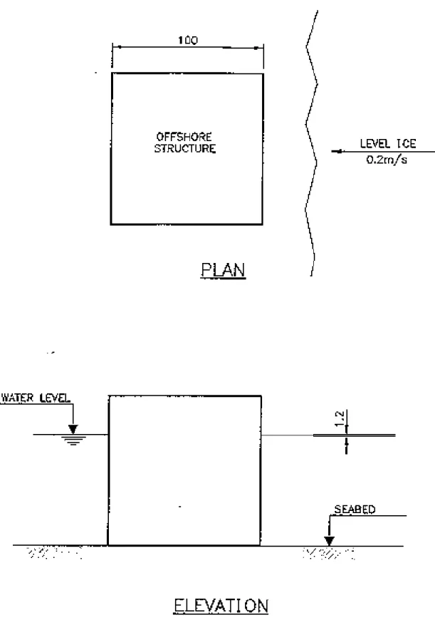
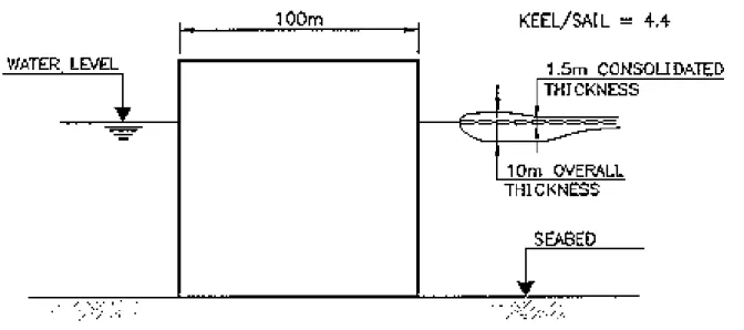
• Scenario 1 - A level sheet of sea ice of 1.2 m thickness interacting with a fixed offshore structure in mid-winter. Assume that the ice is moving at a rate of 0.2 m/s, and the structure is vertical-sided with a width of 100 m and in deep water.
• Scenario 2 - A first-year ridge of total thickness 10 m interacting with the same structure. Assume a keel-to-sail ratio for the ridge of 4.4, a consolidated layer thickness of 1.5 m, and a width of 23 m. Assume that the ridge is embedded in an ice sheet with the same characteristics of Scenario 1.
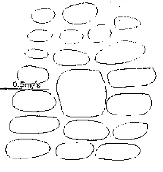
• Scenario 3 - Open pack ice of 1.2 m thickness interacting with a multi-leg structure of 100 m width. Determine the expected load for pack ice concentrations of 0.4 and 0.8
for floe sizes of the order of 10 to 50 m in diameter moving at a speed of 0.5 m/s. Assume that the structure has four 20 m wide cylindrical supporting piers at the four corners.
The approach followed in each of the codes is described by:
• Noting the applicable code clauses that guided the ice load determination.
• Describing relevant ice strength parameters.
• Describing the mechanistic ice load model.
• Identifying any lack of guidance in the code that would have permitted an improved understanding of the ice load determination
• Identifying any assumptions made beyond code guidance.
Task 3 Report
The findings in Task 1 and Task 2 are presented in this report, which is organized into five sections:
Section 1 Introduction
Section 2 Structural Design Approach
Section 3 Ice Design Approach
Section 4 Ice Load Calculations
2
2
.
.
0
0
S
S
t
t
r
r
u
u
c
c
t
t
u
u
r
r
a
a
l
l
D
D
e
e
s
s
i
i
g
g
n
n
A
A
p
p
p
p
r
r
o
o
a
a
c
c
h
h
As indicated, the CSA code has been applied recently to the design of the first Russian offshore platform for deployment in the Sea of Okhotsk where sea ice will induce the dominant environmental loads through the winter seasons. In that design process, there was considerable debate on the different structural and ice design philosophies among the various interested parties - the foreign investor (Sakhalin Energy Investment Company Ltd.), the Russian investor, the foreign investor’s engineer (Sandwell) and the Russian engineering body. The aim was to develop a design that would achieve certification by both western regulatory authorities, such as the American Bureau of Shipping, and the Russian Marine Registry Services, the Russian regulatory authority.
While the focus of this study is ice loading, it is important that the fundamental structural design philosophies in the different codes be examined at the same time because the specification of loads and the design of engineering components to accommodate these loads form the basis for all engineering developments.
This section summarizes the approaches in structural design, the specification of the recurrence interval of design loads, load factors and load combinations for each of the 4 codes.
2
2.
.1
1
CS
C
SA
A
The CSA code for the design of fixed offshore structures consists of 5 principal parts:
S471 General Requirements, Design Criteria, the Environment, and Loads - Part I of the Code for the Design, Construction and Installation of Fixed Offshore Structures
S472 Foundations - Part II of the Code for the Design, Construction and Installation of Fixed Offshore Structures
S473 Steel Structures - Part III of the Code for the Design, Construction and Installation of Fixed Offshore Structures
S474 Concrete Structures - Part II of the Code for the Design, Construction and
Installation of Fixed Offshore Structures
S475 Sea Operations - Part II of the Code for the Design, Construction and Installation of Fixed Offshore Structures
2
2.
.1
1.
.1
1
ObObjjeeccttiivveessThe CSA code was developed with the aim to facilitate designs of offshore structures so that a low risk to the lives of people on or near the offshore structure and a low risk of environmental damage due to any accident or failure are ensured.
The code defines two safety classes for which the recurrence interval and load factors for certain design loads are different:
• Safety Class 1 - failure would result in great risk to life or a high potential for environmental damage
• Safety Class 2 - failure would result in small risk to life and a low potential for environmental damage
Appendix A of CSA S471 tabulates the following code intended annual reliability levels:
• Ultimate limit state, Safety Class 1 1 – 10-5
• Ultimate limit state, Safety Class 2 1 – 10-3
• Serviceability limit state 1 – 10-1
These are considered to be average values and are not met under all loading conditions. These values do not account for advantageous effects of structural redundancy, reserve capacity and ductility. Consequently, the reliability level in a structure designed in accordance with the code provisions may exceed these levels.
To achieve the design objective, the CSA code provides for the use of the limit states design method. This method incorporates load factors and material resistance factors in the design and the aim is to provide factored structure resistance (or capacity) that will exceed the factored loads. Alternatively, the code permits the designer to use known or postulated probabilistic distributions of loads and material resistances to formulate the design, provided that the designer can demonstrate that the level of safety intended by the code is satisfied.
Two categories of limit states are defined in the CSA code:
• Ultimate limit states
Ultimate limit states are structural failure states that concern safety to personnel and the environment. These limit states include overturning, capsizing, sliding, sinking into water or ground, exceedance of structural strength in buckling, fracture, fatigue, fire or deformation, structural instability and progressive collapse.
• Serviceability limit states
Serviceability limit states are behaviour states of the structure that hinder normal functions and reduce durability. These include unacceptable deflections, vibrations and local damage such as cracking and connection slippage.
2
2.
.1
1.
.2
2
LoLoaaddss aanndd LLooaadd CCoommbbiinnaattiioonnThe code specifies that offshore structures are to be designed to resist loads under four categories:
• Permanent loads, G
Dead loads, GD (structure weight, weight of permanent equipment and ballast,
permanent hydrostatic loads).
Deformation loads, GR (prestressing, creep, shrinkage, temperature, differential
settlement, foundation stiffness variation).
• Operational loads, Q
Loads caused by occupancy and operation, storage, crane, helicopter, mooring, berthing, variable ballast and differential hydrostatic pressures.
• Accidental loads, A
Loads caused by accidental events, events with an annual probability of occurrence of less than 10-4 need not be considered.
• Environmental loads, E
Frequent environmental processes, Ef (wind, waves, currents, sea ice, icebergs and
bergy bits, tide, marine growth, snow and ice accumulation, storm surges)
- Loads based on frequent environmental processes have annual probability
of exceedance not greater than 10-2
Rare environmental events, Er (earthquakes and related earthquake effects, icebergs
and other rare ice features, sea ice and tsunamis)
- Loads based on rare environmental events have annual probability of
exceedance not greater than 10-2 for Safety Class 2 structure components and within the range of 10-3 and 10-4 for Safety Class 1 components.
Ultimate Limit States Safety Class 1 1.25 GD + 1.0 GR + 1.25 Q + 0.7 Ef 1.05 or 0.9 GD + 1.0 GR + 1.0 Q + 1.35 Ef 1.05 or 0.9 GD + 1.0 GR + 1.0 Q + 1.0 Er 1.05 or 0.9 GD + 1.0 GR + 1.0 Q + 1.0 A Safety Class 2 1.05 or 0.9 GD + 1.0 GR + 1.0 Q + 0.9 Ef 1.05 or 0.9 GD + 1.0 GR + 1.0 Q + 1.0 Er Serviceability Limit States
1.0 GD + 1.0 GR + 1.0 Q + 0.7 Ef
Guidelines for special design cases such as fatigue design (a particular case of ultimate limit states), design for cyclic loading and design for local concrete damage are also given in the code.
2
2.
.1
1.
.3
3
MeMetthhooddThe CSA code has been developed on the basis of the limit states design method incorporating load and material resistance factors.
The structure is proportioned to have sufficient strength and/or stability such that
Σ γi Fi (effects of factored loads) < φ R (factored resistance)
where
Fi is the stress effect in a structure due to a specified load in a load
combination
γi is the load factor for load type specified in the code φ is the component resistance factor specified in the code
R is the nominal component strength or resistance
The code allows the use of alternative design methods that are based on theoretical analysis and recognized engineering practice in lieu of the design method stated in the code, provided that the design would achieve levels of safety and serviceability at least equal to those targeted by the code requirements. In this respect, the code is very clear in terms of design objectives and allows the code user to choose a design method to satisfy those objectives. Where new systems and materials or new hazards not contemplated by the code are encountered, this code provision is particularly useful and the designer may carry out risk analysis for the specific hazard, system or material in order to arrive at a structural design that would achieve the safety objectives.
2
2.
.2
2
AP
A
PI
I
The API code for the standardization of offshore structures consists of the following publications:
RP 2A Recommended Practice for Planning, Designing, and Constructing Fixed Offshore Platforms - LRFD
Spec 2B Specification for Fabricated Structural Steel Pipe
Spec 2C Specification for Offshore Cranes
RP 2D Recommended Practice for Operation and Maintenance of Offshore
Cranes
Spec 2F Specification for Mooring Chain
RP 2G Recommended Practice for Production Facilities on offshore Structures
Spec 2H Specification for Carbon Manganese Steel Plate for Offshore Platform
Tubular Joints
RP 2I Recommended Practice for In-Service Inspection of Mooring Hardware for
Floating Drilling Units
RP 2L Recommended Practice for Planning, Designing, and Constructing
Heliports for Fixed Offshore Platforms
RP 2M Recommended Practice for Qualification Testing of Steel Anchor Designs
for Floating Platforms
RP 2N Recommended Practice for Planning, Designing and Constructing Structures and Pipelines for Arctic Conditions
RP 2P Recommended Practice for the Analysis of Spread Mooring Systems for
Floating Drilling Units
Bul. 2S Draft Bulletin on the Design of Windlass Wildcats for Floating Offshore Structures
RP 2T Recommended Practice for Planning, Designing, and Constructing Tension
Leg Platforms
Bul. 2U Bulletin on Stability Design of Cylindrical Shells Bul. 2V Bulletin on Design of Flat Plate Structures
Spec 2W Specification for Steel Plates for Offshore Structures, Produced by Thermomechanical Control Processing (TMCP)
RP 2X Recommended Practice for Ultrasonic Examination of Offshore Structural
Fabrication and Guidelines for Qualification of Ultrasonic Technicians
Spec 2Y Specification for Steel Plates, Quenched-and-Tempered, for Offshore
RP 2Z Recommended Practice for Preproduction Qualification for Steel Plates for Offshore Structures
The API publications RP2A (for structural design philosophy) and RP2N (for ice design philosophy) are the primary focus in this study.
As mentioned previously, the standard API RP2A ‘Recommended Practice for Planning, Designing and Constructing Fixed Offshore Platforms’ has undergone an extensive review process in the late 1980’s to early 1990’s. The review concluded that the then existing method of checking safety in structure components, the Working Stress Design (WSD) method, did not provide consistent component reliability. Subsequently, API decided to change the WSD method to the Load and Resistance Factor Design (LRFD) method, which, with its partial factors calibrated by a reliability model, will give structure designs a more consistent component reliability.
2
2.
.2
2.
.1
1
ObObjjeeccttiivveessThe API code states that the Recommended Practices are published to facilitate the availability of proven, sound engineering and operating practices and that consideration is given to the safety of personnel, compliance with existing regulations, and prevention of pollution.
The design requirements given in API RP2A have been formulated on the basis of a reliability analysis, with the target safety indices established from a set of safety indices computed for the designs of a range of platform types developed from applying the earlier WSD method. Load factors in the LRFD format were then computed from these target safety indices. Although the code itself does not state explicitly the implied structural reliability, literature references report that the reliability analysis was based on component design practices in the Gulf of Mexico where wave is the primary environmental hazard, and that the probability of failure for structures designed to API RP 2A is about 0.001 in 20 years, a typical design life for platforms (Nevel, 1997). A probability of failure of 0.001 in 20 years translates into a probability of failure of 0.00005 in 1 year.
The LRFD method, in conjunction with calibrated load factors and resistance factors, is used to achieve the structural reliability objective. The aim in a design is to provide factored nominal structural strengths that are greater than the factored load effects. API refers to the American Institute of Steel Construction code entitled ‘Load and Resistance Factor Design Specification for Structural Steel Buildings’ for the calculation of nominal strengths of most types of steel components.
2
2.
.2
2.
.2
2
LoLoaaddss aanndd LLooaadd CCoommbbiinnaattiioonnssAPI categorizes loads into five groups:
• Gravity loads, D and L
Dead load 1, D1 (self weight, weight of permanent equipment and ballast, hydrostatic
Dead load 2, D2 (weight of equipment and other objects that may change from one
mode of operation to another but otherwise remain constant for long periods of time). Live load 1, L1 (weight of consumables).
Live load 1, L2 (short duration loads such as lifting by cranes). • Wind, Wave and Current loads, W and D
Extreme Wind, Wave and Current load, We (combined action of the extreme wave
(typically 100 year return period) and associated current and wind).
Operating Wind, Wave and Current load, We (combined action of the operating wind,
wave and current condition).
Extreme or Operating Inertial load, Dn (inertial load at the time when the total global
dynamic response is a maximum).
• Earthquake loads, E
Strength Requirements, E (structure to be checked for strength to resist the inertially induced loads produced by the strength level ground motion that has a reasonable likelihood of not being exceeded during the life of the structure).
Ductility Requirements (the global performance of the structure-foundation system must be demonstrated to be satisfactory in response to the rare intense earthquake).
• Fabrication and Installation loads
Installation encompasses the operations of moving the platform components from the fabrication site to the offshore location, and installing them to form the completed platform.
Structure components are to be designed to resist the following factored load combinations:
1.3 D1 + 1.3 D2 + 1.5 L1 + 1.5 L2
1.1 or 0.9 D1 + 1.1 or 0.9 D2 + 1.1 or 0.8 L1 + 1.35 (We + 1.25Dn)
1.3 D1 + 1.3 D2 + 1.5 L1 + 1.5 L2 + 1.2 (Wo + 1.25Dn)
1.1 or 0.9 D1 + 1.1 or 0.9 D2 + 1.1 or 0.8 L1 + 0.9 E (1.15 E for deck supported
structures)
Appropriate load combinations during fabrication and installation, and for fatigue design
2
2.
.2
2.
.3
3
MeMetthhooddAs in the CSA code, the API load and resistance factor design (LRFD) method calls for a design to satisfy the following criterion:
where the load and resistance factors have been calibrated during code formulation using a reliability model. This format is consistent with that adopted by a number of codes in the United States such as the ACI for reinforced concrete, AISC for steel and AASHTO for bridges.
2
2.
.3
3
SN
S
NI
IP
P
A
An
nd
d
v
vs
sn
n
The State Standard “Building Norms and Rules”, SNiP (Stroitelnye Normy i Pravila), is a regulating document and compliance of structural designs with this standard is mandatory. The “Building Norms for Industries”, VSN (Vedomstvennye Stroitelnye Normy) is a code for the Oil/Gas Ministry. It, in principle, must not contradict the SNiP code but supplements and clarifies the major provisions in SNiP. Both the SNiP and the VSN codes have been developed for the Russian offshore.
For the design of marine structures, designers are obliged to follow these standards:
SNiP 2.06.01-86. Marine structures, general design provisions SNiP 2.01.07-85. Loads and influences
SNiP 2.06.04-82*. Loads and influences on marine structures (from waves, ice and vessels), issued in 1996
SNiP 2.02.02-85. Marine structure foundations
SNiP 2.06.08-87. Concrete and reinforced-concrete marine structures
VSN-41.88 Design of fixed ice strengthened platforms
This study focuses on SNiP 2.06.01-86, SNiP 2.01.07-85, SNiP 2.06.04-82* and VSN-41.88.
In principle, the VSN code is intended to supplement and elaborate on SNiP code provisions. However, on issues relating to ice load determination, these codes often contradict each other. In the years leading up to 1996, the SNiP and the VSN codes were accepted for ice load determination for non-overlapping ice speed regimes:
• SNiP is to be used for ice motion more than 0.5 m/sec
• VSN is to be used for ice motion less than 0.5 m/sec
This definition of applicable ice speed regimes for the two codes led to different ice loads calculated using the two codes for an ice speed of 0.5 m/sec. In 1996, this situation was rectified as the sections on ice loads in SNiP were revised to cover all ice speeds.
It is recognized that, because of the scarcity of field experience, the science of ice load determination is still controversial. Consequently, the State Expert Commission, who has the authority to approve projects, is able to accept ice loads determined on the basis of well substantiated mathematical rationale, particularly in the definition of certain parameters such as ice strength and ice ridge characteristics.
2
2.
.3
3.
.1
1
ObObjjeeccttiivveessBoth the SNiP code (SNiP 2.06.01-86) and the VSN code provide for the use of the limit states design method, incorporating load factors and material resistance factors. The aim of the design is to achieve factored resistances (in strength and stability) in the structural elements that will be greater than the effects resulting from factored loads. However, structural reliability is not quantified because the codes do not state explicitly the target probability of structural failure.
The two categories of limit states are described in the SNiP code. VSN refers to the SNiP code on these requirements:
• The first group of limit states that would lead to a cessation in operation
The strength and the stability of the structure-foundation system and its structural components are to be evaluated for failure states which would lead to a cessation in the platform operations.
Examples of a limit state in this group is the loss of global structure stability due to a sliding of the platform on the foundation or the failure of structural elements which would lead to the total collapse of the structure.
• The second group of limit states that would not lead to a cessation in operation
The strength and the stability of the specific structural elements and the local strength of the foundation are to be evaluated. The failure of these components would not lead to a cessation of the platform operations.
An example of a limit state in this group is the loss of local strength in the hull plate on the platform.
2
2.
.3
3.
.2
2
LoLoaaddss aanndd LLooaadd CCoommbbiinnaattiioonnThe SNiP code (2.01.07-85 and 2.06.01-86) specifies the following categories of loads:
• Constant Loads
These are loads that will always act on the structure. Examples are self weight and static soil pressure.
• Temporary Loads
Temporary loads are divided into long term, short term and special loads. Long term temporary loads are operational loads.
Short term loads are environmental (other than earthquake) loads of average magnitudes. For example, ice loads resulting from first year ice (characteristics are determined from many years of observation) of average thickness are classified as short term loads. In practice, short term environmental loads are annual maximum loads.
Special loads are environmental (including earthquake) and explosive loads of ‘maximum’ magnitudes. For example, ice loads resulting from first year ice of maximum (1 in 100 years) thickness are classified as special loads. The probability of exceedance of the special loads is not specified. Bolshev et al, 1997, discussed this issue and suggested the incorporation of a probabilistic model into the design process. Loads determined in accordance with the guidelines in the code are called normative (or specified) loads. For use in design, these loads are to be multiplied by a coefficient of reliability. For example, SNiP 2.06.01-86 specifies that the coefficient of reliability for ice loads is 1.1. In comparison, VSN specifies a value of 1.1 for loads determined for the 100 year return period first year ice thickness and 1.0 for those determined for the average first year ice thickness. Values of this coefficient for various types of loads and limiting conditions are given in the code.
The principles for design load combinations are specified in SNiP 2.01.07-85 and SNiP 2.06.01-86. Load combinations reflecting realistic simultaneous influence of loads on the structure at the various stages in its design life are identified. The most unfavourable load combination would govern the design.
Two categories of load combination are to be considered:
• the main load combinations consisting of constant, temporary long term and short term loads
• the specific load combinations consisting of constant, temporary long term and only one of the special loads
The specified loads are to be factored by the appropriate coefficient of load reliability and then combined by applying the appropriate coefficients of load combination which account for the probability of simultaneous occurrence of the loads.
Main load combinations (from SNiP 2.01.07-85):
1.0 Constant load + 0.95 Temporary long term load + 0.9 Temporary short term load 1.0 Constant load + 1.0 Temporary long term load
1.0 Constant load + 1.0 First temporary load+ 0.8 Second temporary load + 0.6 Third temporary load
Specific load combination:
1.0 Constant load + 0.95 Temporary long term load + 0.8 Special load
Ice loads should be considered as the Special load in the Specific load combination. In addition, in seismically active regions where earthquake would also be considered as a Special load in the Specific load combination, ice loads (or wave loads) should be included as a simultaneous temporary load in that Specific load combination.
These load combinations are to be considered for both categories of limit states during periods of normal operations. For periods of repair and construction, a reduced coefficient is specified in the code.
The VSN code refers to the SNiP code on the subject of load combinations.
2
2.
.3
3.
.3
3
MeMetthhooddSimilar to the CSA and the API approaches, the SNiP code follows a limit state design method with the following design criterion:
Σγ1cγf Fi < R γc /γmγn ,
where
Fi is the stress effect in a structure due to a specified load in a load
combination
γ1c is a coefficient of load combination (described above)
γf is a coefficient of reliability for the specified load (described above)
R is the specified strength of the material (or foundation bearing capacity)
γm is a coefficient of reliability for the material γn is a coefficient of structural reliability γc is a coefficient of working conditions
and for foundation design, the coefficient of reliability for the foundation (ground),
γg, is used instead of γm .
The coefficient of working conditions, γc, is specified by the code for various components
of the structure and takes into consideration the effects of humidity, environmental aggressiveness and other factors not directly accounted in the design. For major structural elements, this coefficient varies from 0.8 to 0.95.
The coefficient of structural reliability, γn, takes into consideration the consequences of
structural failure. Four classes of structure or structural components are defined with the coefficient of structural reliability ranging from 1.25 for Class 1 structures whose failure would have the most serious consequences to 1.1 for Class 4 structures whose failure would have the least serious consequences. For offshore structures, this coefficient is 1.25 for the first group of limit states (that would lead to a cessation of operations) and 1.0 for the second group of limit states (that would not lead to a cessation of operations). All offshore structures are considered to be Class 1 structures.
Material strength is treated in a similar manner. Normative (specified) design values for the material characteristics are associated with a probability of exceedance of 95%. For use in design, the specified material values are divided by a coefficient of material reliability, γm. The material reliability coefficient for steel is 1.1 and, for the various
concrete classes suitable for structures in ice, 1.3.
Specified ground (soil foundation) characteristics are the statistical average values derived from field and laboratory tests. For use in design, these specified characteristics are to be divided by a coefficient of ground reliability, γg , that depends on the number of
field and laboratory tests. A typical value for γg is 1.15. Alternatively, instead of the use of
the coefficient of ground reliability, a design value can be determined by the 95% non-exceedance level in the test results. The treatment of ground strength is therefore seen to be different from the treatment of building material strength.
There are no provisions in the VSN code for material characteristics or principles on design loads.
2
2.
.4
4
Su
S
um
mm
ma
ar
ry
y
C
Co
om
mp
pa
ar
ri
is
so
on
n
Of the four codes, the CSA code is the most explicit, numerically, in stating its intended level of structural safety for the design. The limit states design method is presented in the code as a method for proportioning a structure so that the target level of safety would be achieved. The return periods for design loads are also clearly specified. The code also states clearly that, should the designer choose to use an alternative design method, the intended level of safety must be achieved.
The API LRFD code was developed when it was recognized that its predecessor, the API Working Stress Design (WSD) code, did not provide structure designs with consistent component reliability. It was also recognized that the historical use of the API WSD code did produce designs with levels of reliability that were acceptable to industry. Consequently, the load and resistance factors in the recommended limit states method were developed by calibrating against historical experience so that designs provided by the API LRFD method will have, on average, structural reliabilities similar to those implicit in the designs provided by the API WSD method. A discussion on this topic is given by Nevel in his 1997 publication entitled “Comparison of API and CSA Design Ice Forces”. The return period of design loads is clearly stated in the code.
The SNiP and the VSN codes are, in essence, not separate codes as the VSN code is intended to supplement and clarify the intentions of the SNiP code. The target level of reliability is not mentioned in these codes and the return period of extreme loads is likewise not specified. The VSN code contains no descriptions of limit states, load combinations and provides no guidance with respect to material characteristics and principles on design loads. However, the VSN code does contain recommended values for the coefficients for ice loads which are different from those given in the SNiP code. The limit state method given in the SNiP code is given in a format different from that in the CSA or the API codes in that it contains additional load and material coefficients. It is not clear whether these coefficients, or factors, have been developed with a target level of structural reliability.
In summary, all four codes follow a limit states design method which calls for the proportioning of the structural components such that the factored component resistance is greater than the effects of the sum of the factored loads. In both the CSA and the API formulation, it is clear that a target structural reliability was used in the derivation of the various partial factors and the specified return periods for the design loads. In the SNiP and the VSN codes, with the use of multiple factors on both the component resistance and the loads, for which a return period is not specified, the targeted level of structural reliability is not apparent, nor is the uniformity in component reliability.
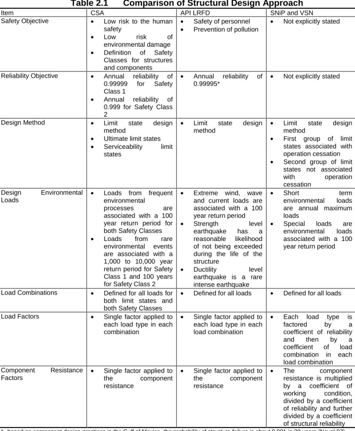
Table 2.1
Comparison of Structural Design Approach
Item CSA API LRFD SNiP and VSN
Safety Objective • Low risk to the human
safety
• Low risk of
environmental damage
• Definition of Safety
Classes for structures and components
• Safety of personnel • Prevention of pollution
• Not explicitly stated
Reliability Objective • Annual reliability of
0.99999 for Safety Class 1
• Annual reliability of 0.999 for Safety Class 2
• Annual reliability of 0.99995*
• Not explicitly stated
Design Method • Limit state design
method
• Ultimate limit states
• Serviceability limit
states
• Limit state design
method
• Limit state design
method
• First group of limit
states associated with operation cessation • Second group of limit
states not associated with operation cessation
Design Environmental Loads
• Loads from frequent
environmental
processes are associated with a 100 year return period for both Safety Classes
• Loads from rare
environmental events are associated with a 1,000 to 10,000 year return period for Safety Class 1 and 100 years for Safety Class 2
• Extreme wind, wave
and current loads are associated with a 100 year return period
• Strength level
earthquake has a reasonable likelihood of not being exceeded during the life of the structure • Ductility level earthquake is a rare intense earthquake • Short term environmental loads are annual maximum loads
• Special loads are
environmental loads associated with a 100 year return period
Load Combinations • Defined for all loads for
both limit states and both Safety Classes
• Defined for all loads • Defined for all loads
Load Factors • Single factor applied to
each load type in each combination
• Single factor applied to each load type in each load combination
• Each load type is
factored by a coefficient of reliability and then by a coefficient of load combination in each load combination Component Resistance Factors •
Single factor applied to the component resistance
• Single factor applied to the component resistance • The component resistance is multiplied by a coefficient of working condition, divided by a coefficient of reliability and further divided by a coefficient of structural reliability
3
3
.
.
0
0
I
I
c
c
e
e
D
D
e
e
s
s
i
i
g
g
n
n
A
A
p
p
p
p
r
r
o
o
a
a
c
c
h
h
3
3.
.1
1
CS
C
SA
A
As discussed in Section 2, the reliability based CSA code clearly specifies that the design rationale is to relate design loads to the target reliability as defined by an annual probability of failure of 10-5 for Safety Class 1 structure components and 10-3 for Safety Class 2. The annual exceedance probabilities for the corresponding environmental loads (which include ice loads), together with the load factors to be used in conjunction, are defined to achieve these target reliability levels. For frequent environmental processes (e.g. formation of first year sea ice), the annual probability of exceedance is 10-2. For rare events (e.g. ice islands), the annual probability of exceedance is 10-4.
CSA S471 also states, in Clause 4.5.2, that if loading hazards can be predicted sufficiently ahead of time to carry out a pre-defined emergency response plan that ensures personnel safety and environmental protection, then, for that particular loading condition, the structure may be Safety Class 2. This statement has particular significance in the design against ice hazards that can be reasonably monitored for the benefit of an offshore operation. An example of such a measure would be the identification of extreme stamukhas, whose characteristics and proximity to the platform, when compared with a set of design criteria, would trigger safety procedures to preserve human safety (e.g. by early evacuation) and damage to the environment (e.g. by well shut-down). This is one method by which the designer might adopt to deal with rare environmental loads. The concept of a structure being Safety Class 2 for a particular loading condition is an important one – the structure may be Safety Class 1 for earthquakes or other rare environmental loads which cannot be readily monitored or predicted.
In Clause 4.11, the code further states that where ice management measures are to be used to reduce global or local design ice loads, the reliability of the procedures shall be consistent with the intended safety for the structure or for the particular structural element. This statement emphasizes the importance of evaluating ice management measures, an example would be icebreaker support, in accordance with the code intended reliability levels.
3
3.
.1
1.
.1
1
IcIcee FFeeaattuurreessClause 5.4 of CSA S471, supplemented by Appendix E to the code, provides a check list of ice data necessary to characterize the regional ice regime. The ice types to be considered include:
• First year sea ice
• Multi-year sea ice
• Glacial ice
Ice features to be considered include: • Ice floes
• Rafted ice • Hummock fields • Icebergs • Bergy bits • Growlers • Ice islands
Mechanical and physical properties of these ice features are be to be determined, including:
• Compressive strength
• Flexural and tensile strengths
• Shear strength
• Fracture toughness
• Elastic modulus
• Salinity
• Temperature
• Brine volume and porosity
• Density
• Crystallography
In addition, regional characteristics are to be determined on the basis of field data and, if required,
by analyzing the influences from wind, wave and current, on a seasonal and year-to-year basis, on
the ice hazards. These characteristics include:
• Ice thickness
• Ice flux and concentration
• Ice velocity
The distribution statistics of these ice parameters are to be generated so that ice loads for the code
specified probabilities of annual exceedance can be rationally computed.
3
3.
.1
1.
.2
2
StStrruuccttuurree TTyyppeessRecommendations are provided for the determination of ice loads on a full range of structural shapes:
• Vertical sided structures, narrow or wide
• Slope sided structures, narrow or wide, upward breaking or downward breaking
• Structures founded on a soil berm
Guidance is also given for considering slender structures for which cyclic ice loading is identified as a phenomenon for which the design must accommodate. The potential for liquefaction of the foundation material under cyclic ice loading is also identified as a major design consideration.
3
3.
.1
1.
.3
3
IcIcee LLooaaddssCSA S471 states that ice loads should be determined for the specified return periods on the basis of field data, physical model data or theoretical methods and by considering a number of factors, including:
• environmental driving force
• geometry of the ice feature and of the structures
• mechanical properties of the ice feature
• ice speed
• geometry of the ice/structure contact
• ice clearing around the structure
• inertial effects in both the ice and the structure
• hydrodynamic effects
• effects of ice rubble
Appendix E of CSA S471 gives an introduction to a comprehensive set of current ice determination methods.
It is recognized in the code that it is usual to determine the peak global ice load on a structure, which is then applied as a quasi-static design load for the proportioning of the structure. Such global ice loads are established by one of three limiting conditions:
• Limit stress
Ice load is governed by the failure of the ice.
• Limit energy (or momentum)
Ice load is governed by the available kinetic energy in the ice feature. This energy is continuously dissipated as the ice crushes against the structure.
• Limit force
Ice load is governed by the available environmental forces (wind, current, waves or ice) driving the ice feature against the structure.
Three approaches are presented for the calculation of limit stress ice loads on vertical sided
structures:
• Indentation equation
At high ice speeds, ice load is characterized by ice crushing. Ice pressure is given by the crushing strength of ice factored by coefficients that take into consideration of confinement, strain rate in the ice, temperature, crystal structure, the presence of brine and air in the ice. This is based on Korzhavin’s work.
• Creep analysis
At slow strain rates, ice failure against a structure can be characterized by creep behaviour using numerical or reference stress methods.
• Empirical treatment of large-scale data
It is suggested that empirical treatment of large scale data is the most promising approach to ice load determination.
On sloping structures, a number of ice load models are referenced for the simulation of level ice or ridged ice riding up onto the structure’s surface and fails in a flexural mode. Considerations for potential adfreeze and rubble formation are recommended.
A qualitative description of the methodology for deriving limit energy or limit momentum ice loads is given. Similarly, methods for determining limit force ice loads are described and referenced.
Discussions on cyclic ice loads associated with structural vibrations are also given in Appendix E. It is recommended that a thorough analysis be made when dynamic structural response appears to be possible, taking into consideration of
• ice failure structure attributes such as the mass, stiffness and damping of the
structure
• ice feature characteristics such the thickness, speed and strength
• potential modes such as crushing, flexural, flaking and buckling
A number of references are cited for local ice pressures and their relationship with contact area and the aspect ratio of the contact area.
3
3.
.2
2
AP
A
PI
I
Similar to the CSA code, the API recommendations for designing an offshore structure for ice conditions are given on the basis of a target structural reliability. Ice loads corresponding to a return period of 100 years (an annual probability of exceedance of 10
-2) are to be considered for structural design.
API recognizes that rare large ice features may cause an exceptional class of loading and accepts that the owner may decide to accept the risk of damage to the platform facility without loss of life or damage to the environment. To permit such eventuality, API calls for procedures to be implemented that would allow an orderly shutdown and abandonment of the platform. Such procedures would include a monitoring system and could involve active mitigative measures such as an ice management system.
3
3.
.2
2.
.1
1
IcIcee FFeeaattuurreessThe code provides descriptions and cites references for the possible ice feature types:
• first year floes
• rafted ice
• first year ridges
• rubble features
• multi-year floes and ridges
• icebergs
• natural ice islands
Similarly, the physical and mechanical properties of the ice features to be considered are described:
• crystal structure
• temperature
• salinity
• porosity and brine volume
• specific gravity
• friction
• elastic properties
• strengths, including tensile, flexural, compressive, shear and adfreeze
References are cited for descriptions of ice climate for the Alaskan offshore, including the Beaufort Sea, the Chukchi Sea and the Bering Sea. Ice condition is described by ice coverage and ice movement for three ice zones the Alaskan offshore:
• landfast ice zone where semi-stable ice is attached to the shore
• pack ice zone where ice moves continuously
• transition zone where rough ice occurs between the landfast and the pack ice
The potential for the ice to become adfrozen to the structure, as well as other thermal effects, also needs to be considered.
The code recognizes the large variability of ice feature geometry and recommends, in accordance with the reliability concept, that probability distributions be established to describe ice feature geometry and ice conditions:
3
3.
.2
2.
.2
2
StStrruuccttuurree TTyyppeessSimilar to the CSA code, the API provisions cover a full range of structures. The code recognizes
that
• jackets
• gravity based structures
• gravel islands
• caisson retained islands
• spray ice islands
have been deployed in ice covered waters. The code tabulates the relevant ice design
considerations for three structure types:
•
vertical
•
multi-leg
•
conical
The code recognizes that dynamic ice crushing may induce high forces and that the dynamics of
both the structure and its foundation should be taken in to consideration.
3
3.
.2
2.
.3
3
IcIcee LLooaaddssAPI RP2N and its commentary give a comprehensive description of a procedure for calculating ice loads probabilistically and its rationale in a structural reliability framework. Even so, the code allows for the deterministic determination of ice loads.
The parameters that determine the ice load arising from a particular ice event include:
• type of ice feature
• size, shape, orientation and speed of ice feature
• ice properties
• ice failure mode
• size, shape and stiffness of the structure
Similar to the CSA, ice loads are categorized into three groups:
• loads limited by driving forces
• loads limited by ice momentum
• loads limited by ice failure
For ice loads limited by driving forces, provisions are given for driving forces arising from three
factors:
• water current
• wind
• ice cover, frequently taken as the ridge building force
A description of ice loads limited by the momentum or energy in the ice feature is given, including considerations for mechanical properties consistent with rapidly occurring loads, hydrodynamic added mass and eccentric hits.
Descriptions of ice failure modes are provided for the determination of ice loads limited by ice failure. Four fundamental failure modes are states:
• crushing, which can be further divided into creep crushing, intermittent crushing and continuous crushing
• bending
• buckling
• splitting
Descriptions of theoretical models of these failure modes are provided and suggestions for the use of ice pressures measured in the field for design are made. The use of model tests to verify theoretical models or to serve as design tools is also discussed.
Similar to the CSA code, references and discussions are provided for the consideration of dynamic crushing loads and local ice pressures.
3
3.
.3
3
sn
s
nI
Ip
p
a
an
nd
d
V
VS
SN
N
Ice design approaches are given in both SNiP 2.06.04-82* and VSN-41.88. While the VSN code
is intended to supplement the SNiP code, there are differences in the ice design provisions in these
two codes.
The annual probability of exceedance (or return period) of the design ice load is not specified in
these codes. However, the annual probability of exceedance for some ice characteristics is
specified to be 10
-2, these characteristics being ice thickness and the ice floe dimensions. As
different ice hazards/features are characterized by different parameters, the ice loads resulting
from these ice hazards/features do not appear to have a uniform risk.
3
3.
.3
3.
.1
1
IcIcee FFeeaattuurreessThe SNiP and the VSN codes consider only two types of ice formation, namely first year level ice and ridged ice, and that these ice features may impart loads on offshore platforms in the following manners:
• Pack ice moving against the structure
• Stationary ice pack being driven by wind and current
• Thermal expansion of a consolidated ice pack
• Adfreeze effects under tidal influence
Both codes use semi-probabilistic methods for the determination of ice characteristics for computing ice loads. Probabilistic distributions are used to describe these characteristics and a value at a prescribed probability of annual exceedance is selected for load determination. For example, to compute loads from level ice, the following characteristics are used:
• the level ice thickness at the 1% probability of annual exceedance level
• an ice floe area at its 1% probability of annual exceedance level
• to determine ice strength, VSN specifies the use of the average temperature on the coldest 6 day period over a 5 year observation period whereas SNiP recommends the use of an average temperature over a few days before the day for which the ice loads are to be determined; this period depends on the ice thickness
From this, it is evident that the probability of exceedance for the ice load thus computed is not explicitly established. Furthermore, VSN’s recommendation for the simultaneous consideration of the ‘maximum’ ice thickness and the ‘minimum’ air temperature (thus ‘maximum’ ice strength) is unreasonably conservative.
The codes do not contain any provisions for other ice features such as:
• rafted ice
• broken ice
• icebergs
• stamuchas
3
3.
.3
3.
.2
2
StStrruuccttuurree TTyyppeessThe codes contain provisions for determining ice loads on the following structure types:
• Vertical sided structures, monopods (e.g. columns, piles, piers) and wide structures
• Slope sided structures
The effect of structure width on ice loads is taken into consideration by the use of the aspect ratio parameter. The SNiP code divides vertical sided structures into monopods and wide structures but strict definitions of these structure types are not given. As the specified formulae for computing ice loads on these structure types are different, the designer must exercise judgment as to which formula is applicable.
3
3.
.3
3.
.3
3
IcIcee LLooaaddssAs mentioned previously, the codes consider only two types of ice features, namely level ice and
ice ridges. However, the recommendations for determining ice loads due to ice ridges consist only
of a ridge coefficient which is to be applied to ice loads calculated for level ice conditions. The
magnitude of the ridge coefficient ranges from 1.3 to 2.0, depending on the geographic location.
For the Arctic seas and the seas of the russian Far East (Bering Sea and the Sea of Okhotsk), SNiP
permits the use of a ridge coefficient of 2.0 if it is substantiated.
SNiP provides guidance on the determination of global ice load only whereas VSN contains a
contact area dependent local ice pressure recommendation. Ice speed is reflected in SNiP by
incorporating a strain rate dependent ice strength. In VSN, the condition on ice speed is that it
must be less than 0.5 m/s. Ice induced vibration is not treated in the codes.
VSN considers only limit stress ice loads. SNiP considers also ice loads limited by the available
momentum in the ice feature and driving force by wind and current only. Driving force due to
ridge formation is not treated in the code.
The limit stress method provisions in SNiP and VSN are based on Korzavin’s formula, as
referenced also in the API code. Ice load is given by:
p = P / A = ko kv Rc
and
A = b h where:
p is ice pressure over contact area
P is the ice load
Rc is ice strength
A is the ice/structure contact area
b is the width of the contact area, taken as the width of the structure
h is the ice thickness
kv is a coefficient accounting for strain rate
in SNiP, the value is dependent on the characteristic strain rate ε, with strength value peaking at a strain rate between 10-4 and 5x10⁻⁴, as opposed to 10-3 as suggested in studies by Timco, Michel and others
ko is a coefficient accounting for the aspect ratio of the contact zone
in VSN, the value ranges from 6.0 to1.0 in SNiP, the value ranges from 5.7 to 1.5
Size effect is not taken in consideration in the SNiP and VSN provisions.
The limit momentum method provisions in SNiP are similar to those in the API code although the equations are somewhat different.
The provisions for determining ice loads on sloping structure faces are based on Ralston’s method as described in the API code.