Publisher’s version / Version de l'éditeur:
Engineering Journal - American Institute of Steel Construction, 37, 1st Quarter 1,
pp. 13-24, 2000-01-01
READ THESE TERMS AND CONDITIONS CAREFULLY BEFORE USING THIS WEBSITE.
https://nrc-publications.canada.ca/eng/copyright
Vous avez des questions? Nous pouvons vous aider. Pour communiquer directement avec un auteur, consultez la
première page de la revue dans laquelle son article a été publié afin de trouver ses coordonnées. Si vous n’arrivez pas à les repérer, communiquez avec nous à PublicationsArchive-ArchivesPublications@nrc-cnrc.gc.ca.
Questions? Contact the NRC Publications Archive team at
PublicationsArchive-ArchivesPublications@nrc-cnrc.gc.ca. If you wish to email the authors directly, please see the first page of the publication for their contact information.
NRC Publications Archive
Archives des publications du CNRC
This publication could be one of several versions: author’s original, accepted manuscript or the publisher’s version. / La version de cette publication peut être l’une des suivantes : la version prépublication de l’auteur, la version acceptée du manuscrit ou la version de l’éditeur.
Access and use of this website and the material on it are subject to the Terms and Conditions set forth at
Design of concrete-filled hollow structural steel columns for fire
endurance
Kodur, V. K. R.; MacKinnon, D. H.
https://publications-cnrc.canada.ca/fra/droits
L’accès à ce site Web et l’utilisation de son contenu sont assujettis aux conditions présentées dans le site LISEZ CES CONDITIONS ATTENTIVEMENT AVANT D’UTILISER CE SITE WEB.
NRC Publications Record / Notice d'Archives des publications de CNRC:
https://nrc-publications.canada.ca/eng/view/object/?id=54202118-72dc-4ffb-bbdc-cfd74cce5e74 https://publications-cnrc.canada.ca/fra/voir/objet/?id=54202118-72dc-4ffb-bbdc-cfd74cce5e74Design of concrete-filled hollow structural steel
columns for fire endurance
Kodur, V.K.R.; MacKinnon, D.H.
NRCC-43992
A version of this document is published in / Une version de ce document se trouve dans :
Engineering Journal-AISC, v. 37, no. 1, Jan. 2000, pp. 13-24
ABSTRACT
T
he benefits of steel Hollow Structural Sections (HSS) from an aesthetic and structural point of view have long been recognized by Architects and Engineers in Canada, and more recently in the United States. However, when Building Codes require structural fire protection, the cost of providing such protection can be expensive for exposed members. Filling an HSS column with concrete not only improves the capacity of member through composite action at ambient temperatures but also provides fire endurance periods of up to 2 hours depending on the load level, section size, concrete strength and reinforcing characteristics. Physical tests and parametric studies recently completed at the National Fire Laboratory in Ottawa have resulted in design equations which predict the load carrying capacity and fire endurance period of concentrically loaded HSS columns filled with plain concrete, bar-reinforced concrete and steel fibre-reinforced concrete. The design method is presented, case studies are used to illustrate potential applications, and practical suggestions are made regarding construction techniques. The need for further research is also discussed.INTRODUCTION
Steel hollow structural sections (HSS) were first used as structural framing components in Canada in the early 1970's and, more recently, have gained popularity in the United States. Engineers find them to be very efficient structurally in resisting compression loads and Architects like them since they are more pleasing than other shapes when exposed. In addition to the high profile projects such as the roof structure of the SkyDome in Toronto and the United Airlines Terminal at the O’Hare International Airport in Chicago, HSS are widely used as columns in the construction of ordinary steel
framed one storey structures and are being considered more often in two and three storey buildings now that connections involving these tubular members are better understood (1, 2).
One of the major safety requirements in building design is the provision of appropriate fire protection to structural members. This requirement can be attributed to the possibility of an unsuppressed fire causing a structural collapse or spreading to the floor above, both of which endangers the safety of evacuating occupants and emergency responders. The integrity of the horizontal fire separation or load carrying structure leads to the requirement that the supporting columns have equivalent fire endurance. Building codes in Canada (3) and the United States (4) establish the length of time that a fire separation must contain a fire and the structural elements must endure a fire, based on the building's occupancy, size and height.
Tubular columns are often filled with concrete in order to achieve increased load-bearing capacity through steel-concrete composite action. Concrete filling also increases fire resistance. Through the utilization of a concrete core, external fire protection required for the steel column can be eliminated, thus increasing the usable space in the building. Further, properly designed concrete-filled hollow steel columns can lead, in an economic way, to the realization of architectural and structural design with visible steel without any restrictions on fire safety.
Recently, the National Fire Laboratory (NFL), Institute for Research in Construction, National Research Council Canada, in partnership with the Canadian Steel Construction Council and the American Iron and Steel Institute, developed guidelines for the simplified design and construction of concrete-filled HSS columns. Both experimental and theoretical studies, using computer models, were carried out to investigate the influence of concrete filling on the fire resistance and load capacity of HSS columns.
NRC STUDIES Fire Tests
Fifty-eight concrete-filled tubular columns were tested to failure by exposing the columns to fire. The columns were of circular and square cross sections and were filled with three types of concrete; namely, plain concrete (PC), bar-reinforced concrete (RC) and steel-fibre reinforced
Design of Concrete-Filled Hollow Structural Steel
Columns f o r F i r e E n d u r a n c e
VENKATESH K.R. KODUR and DAVID H. MACKINNONVenkatesh K.R. Kodur, Ph.D., P.Eng. is Research Officer, Fire Risk Management Program, Institute for Research in Construction, National Research Council of Canada, Ottawa, Ontario, Canada. David H. MacKinnon, M.A.Sc., P.Eng. is Codes and Standards Engineer, Canadian Steel Construction Council, Toronto, Ontario, Canada.
concrete (FC). No external fire protection was provided for the steel. Figure 1 shows elevation and cross-sectional details of typical circular HSS columns, filled with three types of concrete, used in the experimental study.
The tests were carried out by exposing the concrete-filled columns to heat in a furnace specially built for testing loaded columns. The test furnace was designed to produce conditions, such as temperature, structural loads, heat transfer, to which a member might be exposed during a fire (5).
Most of the HSS columns tested were subjected to a concentric load. Only three columns were tested for eccentric loads. The applied load on the columns varied from about 60% to 140% of the factored compressive resistance of the concrete core and about 10 to 45% of the factored compressive resistance of the composite column calculated according to the specifications of CSA S16.1-94 (6) for the structural steel and CSA-A23.3-94 (7) for the concrete.
During the test, the column was exposed to heating controlled in such a way that the average temperature in the furnace followed, as closely as possible, the standard time-temperature curve of ASTM E119-88 (8) or ULC S101-89 (9).
Full results of the fire tests on HSS columns, filled with PC, RC and FC are given in References 10, 11 and 12. Results
from the fire tests indicate that the fire resistance of PC-filled HSS columns is about 1 to 2 h, as compared to about 15 to 20 min for unprotected HSS columns. For RC-filled columns and FC-filled columns fire resistance as high as 3 h were obtained.
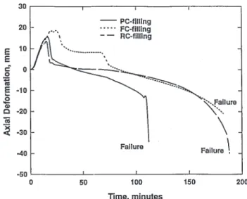
The failure of the columns varied from compression to buckling depending on the size of the column and the type of filling. The majority of the PC-filled columns failed by buckling. Buckling was significant in columns with sectional dimensions less than 203 mm (8 in.). Generally, the failure of PC-filled columns was by sudden contraction, while RC-filled and FC-filled columns failed by gradual contraction.
The behaviour of concrete-filled HSS columns under fire conditions is illustrated in Figure 2, which shows the variation of the axial deformation with time for the three types of concrete-filling (13). These three columns had similar characteristics and were subjected to similar load levels. As expected, the columns expand in the initial stages and then contract leading to failure. The deformation in these columns results from several factors such as load, thermal expansion and creep. While the effect of load and thermal expansion is significant in the early stages, the effect of creep becomes pronounced in the later stages.
Numerical Models
Computer models were developed for predicting the behaviour of PC, RC and FC-filled steel columns in fire (14, 15, 16, 17). The model incorporated realistic stress-stain relationships and the thermal properties for structural steel, concrete, and reinforcing steel at elevated temperatures. The validity of these computer programs has been established by comparing the predictions from the models to test data. The
Figure 1 - Elevation and Cross Section of Concrete-Filled HSS Columns used in Fire Test
Figure 2 - Comparison of Axial Deformations for Concrete-Filled HSS Columns Exposed to Fire
models can account for the important parameters that influence the fire performance of concrete-filled HSS columns.
The computer programs were used to carry out detailed numerical studies (13, 17) to compare the fire resistance of HSS columns with three types of concrete filling. The fire resistance of similar circular and square columns, as obtained from computer models, is compared for three types of concrete filling in Figure 3. The fire resistance of the PC-filled steel columns are much less than the fire resistance of the RC and FC-filled columns. The fire resistance of the FC-filled HSS columns is almost the same as that of the RC-filled HSS columns.
Although it is possible to use the computer models for fire resistance design, the calculation procedure is elaborate and requires considerable skill and effort. A method more suitable for general application and incorporation into codes, is the use of design formulas in line with conventional design procedures.
Parametric Studies
The computer programs described above were used to carryout detailed parametric studies to generate a large amount of data on the fire resistance of concrete-filled HSS columns. Detailed results of the parametric studies are presented by Lie and Kodur (15, 18).
The influence of various factors on the fire resistance of concrete-filled HSS columns was investigated through computer-simulated fire tests. Factors which influence the fire resistance and load capacity of plain concrete-filled HSS columns were found to be:
• outside diameter (width) of steel section, • shape of the steel section,
• wall thickness of steel section, • effective column length, • concrete strength, and • type of concrete aggregate.
The impact of these six factors were found to be similar for bar-reinforced and fibre-reinforced filling. However, the presence of steel-fibre reinforcement was found to have significant influence. For steel-fibre reinforced filling, the content of steel fibres was held constant at approximately 1.77% of the concrete mix by mass (12, 13).
For bar-reinforced concrete-filled HSS columns, two additional parameters have influence:
• percentage of bar-reinforcement, and • concrete cover to bar-reinforcement.
Simplified Equations for Fire Resistance
Based on the data from the parametric studies, expressions were developed for the calculation of the fire resistance of circular and square HSS columns filled with plain concrete, bar-reinforced concrete and steel-fibre reinforced concrete (19, 15, 18). Results from the parametric studies show that the most important parameters that determine the fire resistance of hollow steel columns filled with concrete are:
• Outside diameter or the outside width of the column • Load on the column
• Effective length of the column • Concrete strength
• Type of aggregate
• Type and percentage of reinforcement • Concrete cover thickness to reinforcement
Based on the relationships between the fire resistance and the above parameters, the following formula for the fire resistance of concrete-filled tubular column subjected to axial loading, was established empirically (19, 15, 18):
(
)
(
)
R f f KL D D C c ' = + − 1 2 20 1000 (1) where:R = fire resistance in minutes fc
'
= specified 28-day concrete strength in MPa K = effective length factor
L = unsupported length of the column in mm D = outside diameter or width of the column in mm C = applied load in kN
f1 = a constant to account for the type of aggregate and
the cross-sectional shape of the HSS column. Validity limits were applied to Equation (1) including an upper limit for applied load, C, equal to the compressive resistance of the unreinforced concrete core, Cr
' .
BEHAVIOUR OF COMPOSITE COLUMNS
Results from the above studies can be used to describe the behaviour of composite columns under fire conditions. At Figure 3 - Comparison of Fire Resistance for Concrete-Filled
room temperature, the friction and mechanical bond at the steel concrete interface cause the steel and concrete to move together. Since the strains are the same, both the steel section and the concrete core contribute to the total load carrying capacity of the composite column (i.e. Crc =Cr +Cr
'
). Depending on the size of the steel section, concrete strength, reinforcing, etc., the core contributes from approximately 5% to 50% of the total capacity. For circular columns, the strength of the concrete core is also significantly enhanced due to the confinement provided by the steel tube. The benefit of this confinement effect is accounted for in CSA S16.1-94 (6) by multiplying the resistance of the concrete core, Cr
'
, by an amplifier,τ'
.
As heat is applied, the steel will initially expand longitudinally more rapidly than the concrete and will therefore begin to resist a greater proportion of the applied load as shown in Figure 2. At the same time, the yield strength of the steel and the elastic modulus decreases. Eventually, the steel will yield or buckle locally and the load in the steel begins to shift into the concrete. The steel temperature rises more slowly than that of a column without any concrete filling because of the heat sink effect of the concrete core. This is referred to as a capactive method of fire protection.
It is believed that degradation of the concrete begins when the steel expands. With little or no tensile strength, unreinforced concrete can rupture into blocks along the length of the core leaving horizontal gaps. The addition of bar-reinforcing or steel-fibres helps to delay the start of this degradation. As the temperature increases in the concrete its strength also declines and is accompanied by the moisture in the concrete being driven off. A temporary reprieve of sorts is initiated when the moisture turns to steam, absorbing considerable quantities of heat. This steam needs to be released into the atmosphere to prevent a potential bursting hazard. Hence, vent holes have to be provided in the steel section as described in the following section.
In addition to providing confinement to the concrete core, the steel shell also protects the concrete from direct exposure to the heat source and prevents progressive spalling thus reducing the rate at which the concrete core degrades.
The addition of a 4 or 8 bar reinforcing cage with appropriately designed ties also provides confinement for the concrete core thus the dramatically increased fire endurance periods for this type of concrete filling. Protected first by the steel shell and then by the concrete cover, the temperature in the reinforcing bars increases slowly. However, it was found from the NRC studies (15) that increasing cover beyond the minimum of 25 mm (1 in.) did little to increase the fire endurance period.
Steel-fibres were also found to delay the degradation of the concrete core by providing confinement to the concrete and additional tensile strength. Predictably, load capacity was not increased significantly but the upper limit on fire endurance period increased to 3 hours as compared with 2 hours for plain concrete filling.
Another factor which influenced fire resistance was the shape of the HSS. Concrete-filled circular HSS columns have higher fire resistance as compared to that of concrete-filled
square HSS columns of similar width. The corners of a square section behave like a fin protruding from the core. The concrete and any reinforcing steel in the corners degrade faster because heat can enter through multiple paths.
The NRC studies show that the slenderness of columns also have significant influence on the fire resistance. Lie and Chabot (10) found that slender columns lose their load carrying capacity faster than do stocky columns. The capacity of slender columns can drop well below the resistance of the concrete core alone, Cr
'
. Although stocky circular columns can maintain their strength above Cr
'
, occasions of sudden failure were observed in the test programme. It was found that the fire resistance remains predictable and without sudden failure for loads up to 1.0 times Cr
'
for plain concrete filling, 1.1 times Cr
'
for steel-fibre reinforced concrete filling and 1.7 times Cr
'
for bar-reinforced concrete filling.
DESIGN FORMULA AND CURVES
Using the results from the NRC studies, the Canadian Steel Construction Council published three “Fire Protection Bulletins” (Refs. 20, 21 & 22), proposing a design method, suitable for inclusion in the NBCC (3), for each of the filling types. To facilitate the use of the NRC fire resistance equation by designers, who generally know what fire endurance period is required but need to know the axial load capacity of a member, Equation (1) was rearranged in terms of a maximum load for a desired fire-restance rating. The proposed design method, which includes the three types of filling, is as follows:
Concentrically loaded hollow steel columns that are filled with plain, steel-fibre reinforced or bar-reinforced concrete and are fabricated and erected within the tolerances as stipulated in CAN/CSA-S16.1-94, “Limit States Design of Steel Structures” (6) shall be assigned a fire-resistance rating, R, provided:
C≤Cmax (2)
where
C = axial compressive force due to dead and live
loads (kN) without load factors,
Cmax =
(
)
(
)
a f D R KL c ' + . − 20 1000 2 5 2 (3)but shall not exceed 1.0 times Cr '
for HSS columns filled with plain concrete, 1.1 times Cr
'
for HSS columns filled with steel-fibre reinforced concrete, and 1.7 times Cr
'
for HSS columns filled with bar-reinforced concrete,
a = constant as specified in Table 1,
fc'
= specified compressive strength of concrete in accordance with CSA A23.3, “Design of Concrete Structures,” (7), MPa,
TABLE 1
VALUES OF CONSTANT ‘a’ IN EQUATION (3) Aggregate type* Filling type Steel reinforcement Circular columns Square columns S PC N/A 0.070 0.060 S FC » 2% 0.075 0.065 S RC 1.5%-3% 0.080 0.070 3%-5% 0.085 0.075 N PC N/A 0.080 0.070 N FC » 2% 0.085 0.075 N RC 1.5%-3% 0.090 0.080 3%-5% 0.095 0.085
* Type S concrete is made with siliceous coarse aggregate; Type N concrete is made with carbonate coarse aggregate.
TABLE 2
VALIDITY LIMITS FOR THE USE OF PROPOSED EQUATION (3) Concrete Filling
Parameters Plain Steel-fibre reinforced Bar-reinforced
fc' (MPa) 20 to 40 20 to 55 20 to 55
D (round) (mm) 140 to 410 140 to 410 165 to 410
D (square) (mm) 140 to 305 102 to 305 175 to 305
Reinforcement (%) N/A » 2% of the concrete mix by
mass
1.5% to 5%, with limits on size, number and spacing of bars and ties in accordance with CSA
A23.3.
Concrete Cover (mm) N/A N/A 25
R (minutes) ≤120 ≤180 ≤180
KL (mm) 2000 - 4000 2000 - 4500 2000 - 4500
Class* 1, 2 or 3 1, 2 or 3 1, 2 or 3
D = outside diameter of a round column or outside width of a square column, mm,
R = specified fire endurance period, minutes,
KL = effective length of column as defined in
CAN/CSA-S16.1, “Limit States Design of Steel Structures,” (6), mm, and
subject to validity limits in Table 2.
Notes for Figures 4(a) through 4(d):
(1) Cr
'
is calculated in accordance with Clause 18.4 of CAN/CSA-S16.1-94 (6), Cr ' =0.85 cf Ac
[
1 0.25 0.5]
' c c 2 c 4 c 2 φ λ− + λ− − λ− where φc = 0 60. , fc '= compressive strength of concrete, MPa
Ac = area of concrete, mm2, λc = KL r f E c c c ' π2
rc = radius of gyration of the concrete area,
Ec = initial elastic modulus for concrete, considering the effects o long-term loading.
=
(
1+S)
2500T fc
'
for normal weight concrete, where is fc
'
expressed in MPa, S is the short-term load and T is the total load on the column. Column design curves have been derived based on S
T=0 25. . Confinement effects are ignored by setting
τ τ= =' 1 0 (6)..
(2) HSS designations and dimensions are as given in the
CISC Handbook of Steel Construction (23).
(3) Two unobstructed vent holes, each not less than 12.7 mm
in diameter shall be provided at opposite ends of the column and at each intermediate floor to vent steam. The holes shall be located 150 mm from a base plate, cap plate or concrete slab. Pairs of holes should be orientated such that adjacent pairs are perpendicular (17).
In the above design method, the fire resistance is expressed in terms of structural design parameters. This offers a convenient method of integrating the fire resistance design with structural design. Using these equations, a designer can arrive at a desired fire resistance value by varying different structural parameters, such as length, load, diameter (width), and concrete strength. The use of these equations leads to an optimum design that is not only economical but is also based on rational design principles.
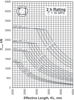
In order to make the design process simpler, the CSCC “Fire Protection Bulletins” (20, 21, 22) also contain design charts, for different fire resistance ratings, wherein Cmax is
plotted as a function of effective length for various column dimensions and concrete strengths. Figure 4 shows four such design graphs for circular and square HSS columns and
having a 2 and 1 h fire resistance rating. For hollow structural sections commonly available in Canada, the Cmaxfor concrete
strengths of 30 MPa and 50 MPa can be read from the design charts.
The design method for concrete-filled HSS columns can easily be programmed into an electronic spread sheet, and with only the HSS dimensions and wall thickness needed to calculate geometry, the designer can utilize Equation (2) directly.
The design method specified above and related design curves dealing with plain concrete-filled HSS columns has been incorporated into Appendix D of the 1995 version of the National Building Code of Canada (3). Appendix D provides conservative methods for calculating the fire resistance of building components as an alternative to using furnace testing. For the other types of concrete fillings, the revised design method is being submitted for the 2001 version of the NBCC. Similarly, the soon to be published ASCE Standard for Fire Resistance Design (24), incorporates the design method for plain concrete-filled HSS columns. It is expected that this Standard will be referenced by model building codes in the United States as an alternative to furnace testing. Equations corresponding to the other two concrete fillings will be proposed for the next edition of this Standard.
To assist designers and constructors in the use of concrete-filled HSS columns, the National Research Council, in collaboration with the Canadian Steel Construction Council, is developing of a Design Guide, to be published in 1998, which will aid in the fire resistance design of these columns.
DESIGN AND CONSTRUCTION CONSIDERATIONS
Some designers are under the impression that concrete-filled HSS columns are protected from fire by the heat sink effect of the concrete filling. This view is not only incorrect, but a dangerous misconception. The behaviour of concrete-filled HSS columns in a fire has been described above and detailed elsewhere. The shedding of load from the steel shell to the concrete core, which eventually carries most of the axial load, means that the designer must pay attention to methods of loading and other practical details not considered in the normal course of structural design. This section lays out some guidance on the design and construction of concrete-filled HSS columns.
Eccentric loading
The design method proposed above is based on the assumption of axial loads on the column. A few tests have been carried out at the NRCC (10, 12) on eccentricity loaded columns but with relatively small eccentricities. Although it is unlikely that the proposed design method would be suitable for beam-column design, small moments could be accommodated. In Canada and the United States, the load combination for fire effects is 1.0 Dead + 1.0 Live. Consequently, the only moments are due to unbalanced gravity loads and if sufficiently small, could either be neglected or assumed to be resisted by a heavier walled
Figure 4 - Fire Resistance Design Graphs for Concrete-Filled HSS Columns (c) Steel-fibre reinforced
(b) Bar-reinforced (a) Plain
section. If longer fire endurance periods are necessary or larger moments are present, higher bending resistance could be achieved by adding additional bar-reinforcement. In any case, combined axial load and bending should be checked at ambient temperature using methods for composite columns found in References (6, 25).
HSS wall thickness
The thickness of the HSS wall was not found to have significant influence on the fire endurance of concrete-filled HSS columns. Consequently, neither the wall thickness nor the area of steel section is a parameter in the proposed design method above. In fact, using a wall thickness greater than that required to ensure that the HSS section is at least a class 3 section in bending, reduces the load carrying capacity for a given fire endurance period. Increasing the wall thickness reduces the size of the concrete core which is the dominating parameter. In general, it is more economical to keep wall thickness to a minimum unless other factors such as connection details dictate otherwise.
Load application and connections
In the furnace tests, the axial load was applied through a sizeable cap plate and the reactions taken out through a matching base plate. The Canadian and US steel design standards (6, 25), require direct bearing of load and reaction at the top and bottom of a composite column. Direct bearing insures that loads are distributed between the steel shell and the concrete core immediately and, without reliance on friction or mechanical bond at the steel-concrete interface, to transfer longitudinal shear. In a fire situation, the steel and concrete are expanding at different rates and the steel shell
softens, shedding load. It would be unwise to rely on friction or mechanical bond under these circumstances.
However, the Canadian standard (6) now allows horizontal members to be framed into the column at intermediate floors. Although no guidance is given on the transfer of load, it would be prudent for the designer to check that the steel section is capable of carrying the additional load until a portion can be transferred into the concrete through friction (mechanical bond is too variable and should be ignored). The question is, should this connection also be allowed in a fire situation? If a fire on a lower level heats the column at that level, the authors believe that the ability of the steel-concrete interface to transfer the load into the concrete is doubtful. An alternate load path, up the cooler steel of the level above and into the concrete core is possible but unproved. An alternative is to use a through plate connection as illustrated in Figure 5 to help transfer loads into the core at ambient temperatures and during a fire.
Steam venting
When concrete-filled HSS columns are exposed to fire, water is driven from the concrete and heat energy is absorbed as it turns to steam. This has some influence on the fire endurance period of the composite column but also presents a potential bursting hazard if the steam is not released to the atmosphere. The recommended number, size, location and configuration of the vent holes as described earlier, is based on the experimental studies at NRC (10, 11, 12). The designer must ensure that the vent holes will not be blocked or covered by poured slabs, concrete block, and wall, window or door frames. The vent holes may be blocked during the concrete placing stage but blocking removed once the concrete has set. The concrete protruding from the vent holes can be smoothed and painted to blend with the finish on the exposed steel is desired.
Concrete filling methods
Concrete filling of HSS columns requires no special equipment and the filling operation may be integrated into other concreting operations. Typically, the concrete is placed into the HSS column after it has been erected and temporarily braced. Temporary bracing is usually required because attached beams are in direct bearing and concreting must take place before they can be erected. A working platform is suspended from the top of the column and a hopper with elephant’s trunk type chute lead into the top of the HSS column. The same crane doing the erection can hoist the concrete bucket. Normal good practise for concrete placing, including drop heights and consolidation through vibrating, need to be followed. Care must be taken to eliminate or minimize the gap between the top of the concrete core and the underside of the cap plate.
If many columns are to be filled, contractors can set-up an area where they can be filled in groups either in vertical or inclined positions. One potential problem with inclined pouring is control of the gap between concrete and cap plate. Concrete pumping can be used either from the top or the bottom. It has been suggested that concrete could be pumped Figure 5 - Through Plate Connection
through a hole at the bottom of the column while air is forced out through the already required vent holes at the top. This approach would simplify co-ordination of trades considerably by allowing the steel frame to be fully erected and plumbed before concreting took place.
CASE STUDIES
Concrete-filled HSS columns have been used primarily in schools and other assembly type occupancies in two and three storey buildings where structural fire protection is required. Interior columns supporting mezzanines and exit stair wells is another common application. In jurisdictions where non-combustible roofs must also be protected, concrete-filled HSS columns are also useful for fire protection in one storey buildings. This section describes three such existing buildings where plain and bar-reinforced concrete filled HSS columns have been used.
Museum of Flight, Seattle, Washington
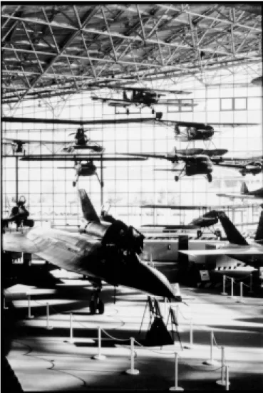
The Museum of Flight at King County Airport is the largest air and space museum on the west coast of the United States and is home to one of the most extensive aircraft collections in the world (17). The 13,300 m2 (143,200 ft.2) museum is dominated by a six-storey-high “Great Gallery,” (Figure 6) constructed as part of a three-part extension, and is composed of a main steel-and-glass exhibit hall, a library, a 268-seat auditorium, and office and conference space. The irregularly shaped building is 148 m (185 ft.) long, 76 m (250 ft.) wide, and 23 m (75 ft.) high.
The architectural requirement for natural light, to see the sky behind the aircraft suspended from the ceiling and the desire to see the exhibits from the outside lead to a glass enclosure supported by a three-dimensional steel frame. Further, the framing members had to be thin so as not to distract from the exhibits, and not to generate any visible noise. Steel tubes were recommended by the structural engineers for the columns. The Authority Having Jurisdiction (AHJ) had adopted the Uniform Building Code (4) which required a 60 minute fire resistance rating for the columns supporting the roof. To avoid the bulk and appearance of sprayed on fire protection, as well as to realize
the beauty of the exposed steel, concrete-filling was adopted. Further, to minimize the size of the columns, reinforcing bars were added to increase the loading carrying capacity at the specified fire endure period.
Although the UBC did not specifically recognize the concept of concrete-filled HSS, the AHJ accepted the test data and analytical work done by the National Research Council (NRC). Using the same mathematical model developed to conduct the simplified design equations above, the NRC study showed that the bar-reinforced concrete-filled HSS columns could provide a fire resistance rating of 60 minutes or higher under full design loads (17).
St. Thomas Elementary School, Hamilton, Ontario
Owned by the Hamilton-Wentworth Roman Catholic Separate School Board, St. Thomas Elementary School is a typical two storey building with an interconnected floor. The open area contains two stair cases and is covered with a glass dome (Figure 7). The natural light and slender members give the space an airy look. To conform with the Ontario Building Code (26), the designers required the columns to have a one hour fire resistance rating. NRC was called upon to use their
analytical techniques, and provided solutions using both square and round HSS with different concrete strengths (17). The designers selected the more elegant round HSS columns and adopted bar-reinforcing for the ground level columns, in order to carry higher loads, and plain concrete-filling for second storey columns supporting the roof.
Correctional Facility
The correctional facility shown in Figure 8 is located in the Canadian prairies. It employs a concrete-filled HSS column in a predominantly concrete building to minimize the view restrictions from the guard’s control room and provide the 2 hour fire resistance rating required for Institutional Building with restrained occupants. A concrete column or structural steel column with conventional sprayed or membrane fire protection would have greatly reduced the site lines. In addition, external fire protection materials could be removed by inmates thus eliminating the members fire resistance and exposing it to attack by fire.
SUMMARY
Concrete filling offers a practical solution for providing fire protection to hollow structural steel columns without any external protection. Results from the experimental and numerical studies indicate that any amount of fire resistance, in the practical range for building construction, can be obtained for HSS columns through three types of concrete filling. The use of fire resistance design equations leads to an optimum design that is not only economical but is also based on rational design principles.
As illustrated in Case Studies, concrete-filled HSS columns are being successfully used, and recognition of the proposed design method by Building Code development groups through direct adoption or preferably, through referenced standards will lead to much wider use of this efficient composite construction system.
REFERENCES
1. Packer, J.A. and Henderson, J.E., Hollow Structural Sections - Connections and Trusses, Canadian Institute of Steel Construction, Toronto, Canada, 1997.
2. American Institute of Steel Construction, Hollow Structural Section Connections Manual, Chicago, Illinois, 1998.
3. Canadian Commission on Building and Fire Codes, National Building Code of Canada, National Research Council of Canada, Ottawa, Ontario, Canada, 1995. 4. International Conference of Building Officials, Uniform
Building Code, Whittier, California, 1997.
5. Lie, T.T., “New Facility to Determine Fire Resistance of Columns,” Canadian Journal of Civil Engineering, Vol. 7, No. 3, pp. 551-558, 1980.
6. Canadian Standards Association, Limit State Design of Steel Structures, CAN/CSA-S16.1-94, Toronto, Ontario, Canada, 1994.
7. Canadian Standards Association, Design of concrete structures, A23.3-94, Toronto, Ontario, Canada, 1994. Figure 8 - Correctional Facility at Alberta, Canada
8. American Society for Testing and Materials, Standard Methods of Fire Tests on Building Construction and Materials, ASTM E119-88, Philadelphia, Pennsylvania, 1988.
9. Underwriters’ Laboratories of Canada, Standard Methods of Fire Endurance Tests of Building Construction and Materials, CAN/ULC-S101-89, Scarborough, Ontario, Canada, 1989.
10. Lie, T.T. and Chabot, M., Experimental Studies on the Fire Resistance of Hollow Steel Columns Filled with Plain Concrete, IRC Internal Report No. 611, National Research Council of Canada, Ottawa, Ontario, Canada, 1992. 11. Chabot, M. and Lie, T.T., Experimental Studies on the Fire
Resistance of Hollow Steel Columns Filled with
Bar-Reinforced Concrete, IRC Internal Report No. 628, National Research Council of Canada, Ottawa, Ontario, Canada, 1992.
12. Kodur, V.K.R. and Lie, T.T., Experimental Studies on the Fire Resistance of Circular Hollow Steel Columns Filled with Steel-Fibre-Reinforced Concrete, IRC Internal Report No. 691, National Research Council of Canada, Ottawa, Ontario, Canada, 1995.
13. Kodur, V.K.R. and Lie, T.T., “Fire Resistance of Hollow Steel Columns Filled with Steel-Fibre-Reinforced Concrete,” Proceedings of the Second University-Industry Workshop on Fibre Reinforced Concrete and Other Composites, Toronto, Ontario, Canada, pp. 289-302, 1995. 14. Lie, T.T. and Chabot, M., “A Method to Predict the Fire Resistance of Circular Concrete Filled Hollow Steel Columns,” Journal of Fire Protection Engineering, Vol. 2, No. 4, pp. 111-126, 1990.
15. Lie, T.T. and Kodur, V.K.R., “Fire Resistance of Steel Columns Filled with Bar-Reinforced Concrete,” ASCE Journal of Structural Engineering, Vol. 122, No. 1, pp. 30-36, 1996.
16. Lie, T.T. and Irwin, R.J., “Fire Resistance of Circular Steel Columns Filled with Fibre-Reinforced Concrete,” ASCE Journal of Structural Engineering, Vol. 122, No. 7, pp. 776-782, 1996.
17. Kodur, V.K.R. and Lie, T.T., “Performance of Concrete-Filled Steel Columns Exposed to Fire,” Journal of Fire Protection Engineering, Vol. 7, No. 2, pp 1-9, 1996. [Also see: Kodur and Lie, "Discussion: Venting Holes in Columns," Vol. 8, No. 1]
18. Kodur, V.K.R., “Design Equations for Evaluating Fire Resistance of SFRC-Filled HSS Columns,” ASCE Journal of Structural Engineering, Vol. 124, No. 6, pp. 671-677, 1998.
19. Lie, T.T. and Stringer, D.C., “Calculation of Fire Resistance of Steel Hollow Structural Steel Columns Filled with Plain Concrete”, Canadian Journal of Civil Engineering, Vol. 21, No. 3, pp. 382-385, 1994.
20. Canadian Steel Construction Council, Fire Protection Bulletin #21, Fire Resistance of Plain Concrete-Filled Steel Hollow Structural Columns, Toronto, Ontario, Canada, 1994.
21. Canadian Steel Construction Council, Fire Protection
Bulletin #25, Fire Resistance of Bar-Reinforced
Concrete-Filled Steel HSS Columns, Toronto, Ontario, Canada, 1997.
22. Canadian Steel Construction Council, Fire Protection Bulletin #26, Fire Resistance of Steel-Fibre-Reinforced Concrete-Filled Steel HSS Columns, Toronto, Ontario, Canada, 1998.
23. Canadian Institute of Steel Construction, Handbook of Steel Construction, 6th Ed., Toronto, Ontario, Canada, 1995.
24. American Society of Civil Engineers, Standard for Fire Resistance Design, New York, New York, 1998.
25. American Institute of Steel Construction, Load and Resistance Factor Design Specification for Structural Steel Buildings, Chicago, Illinois, 1993.
26. Housing Development and Buildings Branch, Ontario Building Code 1990, Ministry of Municipal Affairs and Housing, Government of the Province of Ontario, Toronto, Ontario, Canada, 1990.