HAL Id: hal-01212948
https://hal.archives-ouvertes.fr/hal-01212948
Submitted on 7 Oct 2015
HAL is a multi-disciplinary open access
archive for the deposit and dissemination of
sci-entific research documents, whether they are
pub-lished or not. The documents may come from
teaching and research institutions in France or
abroad, or from public or private research centers.
L’archive ouverte pluridisciplinaire HAL, est
destinée au dépôt et à la diffusion de documents
scientifiques de niveau recherche, publiés ou non,
émanant des établissements d’enseignement et de
recherche français ou étrangers, des laboratoires
publics ou privés.
End-to-end delay analysis in an Integrated Modular
Avionics architecture
Nesrine Badache, Katia Jaffrès-Runser, Jean-Luc Scharbarg, Christian Fraboul
To cite this version:
Nesrine Badache, Katia Jaffrès-Runser, Jean-Luc Scharbarg, Christian Fraboul. End-to-end delay
analysis in an Integrated Modular Avionics architecture. 18th Conference on Emerging Technologies
and Factory Automation (ETFA 2013), Sep 2013, Cagliari, Italy. pp. 1-4. �hal-01212948�
O
pen
A
rchive
T
OULOUSE
A
rchive
O
uverte (
OATAO
)
OATAO is an open access repository that collects the work of Toulouse researchers and
makes it freely available over the web where possible.
This is an author-deposited version published in :
http://oatao.univ-toulouse.fr/
Eprints ID : 12742
Official URL:
http://dx.doi.org/10.1109/ETFA.2013.6648155
To cite this version :
Badache, Nesrine and Jaffres-Runser, Katia and
Scharbarg, Jean-Luc and Fraboul, Christian End-to-end delay analysis in
an Integrated Modular Avionics architecture. (2013) In: 18th Conference
on Emerging Technologies and Factory Automation (ETFA 2013), 10
September 2013 - 13 September 2013 (Cagliari, Italy).
Any correspondance concerning this service should be sent to the repository
administrator:
[email protected]
End-to-end delay analysis in an Integrated Modular Avionics architecture
Nesrine Badache, Katia Jaffrès-Runser, Jean-Luc Scharbarg, Christian Fraboul
University of Toulouse IRIT-INPT/ENSEEIHT
2, rue Camichel, 31000 Toulouse, France
Nesrine.Badache, Katia.Jaffres-Runser, Jean-Luc Scharbarg, [email protected]
Abstract
Recent modular avionics architectures have been de-signed to share computation and communication re-sources. However, such an approach creates new chal-lenges to master the temporal properties of avionics ap-plications.
In the context of IMA (Integrated Modular Avionics), it is crucial to investigate the performance gains that fu-ture integration platforms and software will propose. This paper brings to light the impact of spatial and temporal integration choices on the communication performance (e.g. message loss rate, latencies, ...). The conclusion of this investigation is that it is necessary to conduct a thorough modeling and simulation study of an IMA ar-chitecture integrating several applications during its early design stages.
1. Introduction
Embedded avionics systems have evolved from a fed-erative architecture were calculators where interconnected through dedicated mono-emitter links [2] towards a mod-ular architecture. The Integrated Modmod-ular Avionics (IMA) has been standardized as ARINC 651 standard [4] for the definition of the hardware architecture and as ARINC 653 [5] for the corresponding software architecture. They de-fine the APEX (APplication EXecutive interface) which ensures the spatial and temporal partitioning of the avion-ics functions. Thus, it is possible to design the application software independently from the target IMA physical plat-form.
However, such a modular architecture still necessitates a thorough configuration step at the early stages of its de-sign, both at the physical and software levels. The first point in this article is to evaluate the impact of such config-uration and integration choices on the overall performance of the system. Indeed, sharing communication and com-putation resources in such a modular system increases the complexity of accounting for the temporal properties of the target avionics applications (e.g. execution frequency of functions, communication delays, ...). More specifi-cally, we show that the core of this problem is to evaluate end-to-end communication delays between remotely lo-cated and distributed avionics functions.
This article is organized as follows. Section 2 presents
the relevant assumptions for the integration of avionics applications on an IMA architecture, centered around an AFDX network. In Section 3, the impact of integration choices on end-to-end communication performance is il-lustrated on an example architecture. Section 4 presents the proposed modeling and simulation strategy to compare the communication performance of different architectures for different integrations and configuration choices. Con-cluding remarks and future works are given in Section 5.
2. IMA applications integration
An IMA architecture interconnects several computa-tion modules, sensors and actuators using one or more communication networks. Computation modules commu-nicate mainly using an AFDX network (Avionic Full Du-plex Switched Ethernet) which has been standardized in ARINC 664 [6]. AFDX relies on a switched Ethernet technology and provides communication means for asyn-chronous computation modules. Data is transmitted using the so-called virtual links (VLs) that ensure data flow seg-regation. A VL defines a mono-emitter logical communi-cation path though a sequence of switches. It is character-ized by the minimum time that separates two consecutive frames transmitted by the same source, referred to as the BAG (Bandwidth Allocation Gap) and a maximum frame size SMAX.
An avionics application is composed of a set of func-tions or tasks, which are executed in partifunc-tions that ensure the temporal and physical segregation between applica-tions. These partitions communicate using ports and log-ical APEX channels. Partitions are executed periodlog-ically on the physical modules and are statically scheduled in a cyclical frame called MAF (MAjor time Frame). A par-tition hosts a set of periodic or aperiodic tasks that are scheduled based on a pre-defined policy. Two types of APEX ports exist: sampling and queuing ports. In a sam-pling port, a new piece of data overwrites the previously stored one, whether the old one has been consumed (i.e. read) or not. In contrast, in a queuing port, all incoming pieces of data are stored in their order of arrivals.
In the design of an IMA system, the problem is then to allocate the partitions to the computation modules (spatial allocation), to allocate the APEX channels for the vari-ous communications taking place between the tasks and to define appropriate MAFs (temporal allocation). This integration has to guaranty that end-to-end
communica-tion delays or packet losses are maintained below given limits.
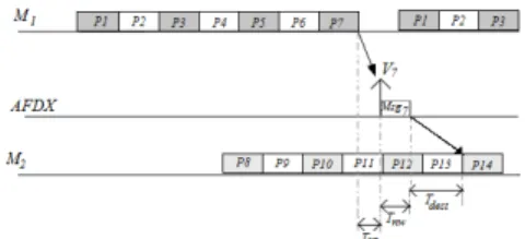
This integration problem is illustrated for the applica-tion presented in Figure 1. This applicaapplica-tion is composed of 14 partitions P1, P2, P14. Each partition Pi, 1 ≤ i ≤ 7,
executes a periodical function Fi. At the end of its
execu-tion, each function (i.e. task) Ficreates a message M sgi
to be sent to function Fi+7. In this example, functions
F1to F6have a period of 32ms while F7has a period of
16ms.
Figure 1. Illustrative IMA example.
The target physical architecture for this application is composed of computation modules interconnected via an AFDX network. A first module M1 is linked to sensors
C1 to C7 whose values are read by functions F1 to F7,
respectively. These functions are hosted by partitions P1
to P7, which are executed in module M1. A second
mod-ule M2is linked to a set of actuators A1to A7which are
commanded by functions F8to F14. Partitions P8to P14
are executed on module M2for functions F8to F14,
re-spectively.
Functions Fi, 1 ≤ i ≤ 7, communicate with is remote
functions Fi+7by sending at the end of each one of their
activation period a message M sgi. The resulting seven
message flows are transmitted from module M1to M2
us-ing seven VLs, V1, . . . , V7, defined in the AFDX port of
M1(M sgi is sent on Vi). We assume that the size of a
message does not exceed the maximum packet size of its VL. A reasonable design for the MAFs of M1 knowing
the periodicity of F1 to F7is to create a MAF of 14ms
repeating itself every 16ms. Each function is executed during 2ms. The MAF of M1 is thus subdivided into 7
slots of 2ms each (cf. Figure 2).
The first six slots are used every two MAF cycles (i.e. every 32ms) by F1to F6, while slot number seven is used
each cycle (i.e. every 16ms) by F7. Accordingly, VLs
V1to V6 are assigned a BAG of 32ms and V7 a BAG of
16ms.
Figure 2. MAFs of modules M1, M2
The MAF of module M2 follows the same model as
M1as shown in Figure 2. M1and M2modules are
asyn-chronous, which means that MAFs can experience differ-ent offsets as the physical module is being started. Unfor-tunately, no simplifying assumption can be made regard-ing these offsets.
3. Impact of applications integration
This section investigates the impact of integration choices on end-to-end communication performance. To this end, we first define the end-to-end communication delay. Then, we show on the example of figure 1 how integration choices impact these delays.
In our analysis, we derive the end-to-end communica-tion delay of the funccommunica-tion F7that transmits the messages
M sg7to the function F14through VL V7. The end-to-end
communication latency is here defined as the duration be-tween the time M sg1 is generated in F7 and the time it
has been consumed by F14. It is decomposed into three
components:
−TV L:M sg1has to wait until a BAG has elapsed
be-fore being transmitted on the VL. TV Lis the time M sg1
is waiting for an available transmission slot in V7. TV L
varies from 0ms to V7BAG size.
−Tnw: the latency the message experiences in the
net-work. It is completely determined by the target network properties.
−Tdest: When M sg1arrives at the incoming port of
M2, it has to wait until function F14is scheduled and can
consume it. Thus, Tdestis the duration M sg1has to wait
in M2before being read by its destination function. These
Figure 3. F7and F14communication
communication latencies are illustrated on our example in the following:
1. Latency for an available VL slot. In the example of figure 3, the MAF of M1 and VL V7have an equal
period (16ms). In this case, TV Lis constant for each
new message instance (cf. TV L on figure 3). Now,
what happens if the period of a function Fxdoes not
match with a possible BAG value (BAGs values are limited to powers of two durations, starting at 8ms)? Let consider a period for Fx of 30ms. The
corre-sponding partition can be allocated in a 30ms MAF cycle. To ensure the availability of a BAG of the VL Vxfrom each message production, the BAG size has
to be fixed to the largest available BAG size which is lower or equal to Fxperiod, i.e. 16ms in this case.
Thus, a message created every 30ms finds an avail-able slot for transmission in the VL of period 16ms.
Consequently, it is possible to control the latency for the VL availability (as long as the message sending period is not lower than the smallest BAG i.e 1ms). 2. Latency through the network. The latency Tnw
consists in two parts: i) the multiplexing delay dmux
on the M1output port and ii) the transmission latency
Tpthrough the network.
a) Multiplexing delaydmux: all the VL data frames
are multiplexed in an ordered sequence according to the messages sending times in the AFDX port. Thus, a data frame of V7arrived after a set of data frames
produced earlier by other VLs will have to wait for complete transmission of previous frames. This mul-tiplexing delay is depicted in figure 5 for three suc-cessive frames of V7of the illustrative example. All
VLs carry here a frame size of 1530 bytes. At 100 Mbps, emission duration is of 0.122ms. The activa-tion of the funcactiva-tion F1to F6 during the first
occur-rence causes a delay of 0.732ms for the data frame of V7. Considering the previously defined BAG values
(16ms for V7, 32ms for V1to V6), the same behavior
is repeated in the third occurrence in V7. However,
the second occurrence of V7 is not affected (dmux
= 0). The difference between the minimum and the maximum dmuxvalue is denoted by multiplexing
jit-ter. When the data frames generation times of the VLs are at the source module ( e.i. modules and VLs offsets are known), this multiplexing jitter can be an-alytically computed [9], otherwise, it requires a re-cursive derivation through simulations.
b) Transmission latency through the AFDX network: it is the difference between the data frame release time from the output of the source module and the re-ception time in the destination module. In an AFDX network, this delay varies depending on the network traffic [10]. Different approaches to bound this vari-ability exist [10]. Some approaches take into ac-count the local scheduling of different VLs originat-ing from the same source. It has also been shown that this local scheduling of VLs can significantly reduces the delays occurred in the network [11].
Figure 5. Multiplexing delay in V7
3. Latency at the destination module. The variation in the latency Tnw means that the successive data
frames received in destination module M2 are no
longer periodic. This is illustrated in figure 6. The function F14is periodic. However, the variable
latency introduced by the AFDX network on M sg7
occurrences results in an additional delay Tdest on
the reception time in the destination module. Since M1and M2are asynchronous, it is impossible to set
execution times of P14on M2to compensate for this
network jitter.
Figure 6. Latency at the destination module M2
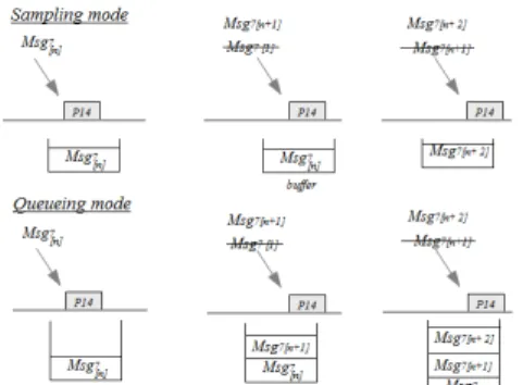
It is therefor possible that two data frames of V7
ar-rive between two successive executions of P14. This
scenario is shown in the figure 7.
Figure 7. Reception in sampling and queue-ing modes
Depending on the type of destination port (queuing or sampling), such successive data receptions have a consequence on the communication performance. The message M sg7n+1 overwritten by the new
oc-currence M sg7n+2. If it is a queueing port, the
mes-sage M sg7n+1 is consumed in the next execution of
P14(n+2). In this case, Tdest> 16ms. To avoid such
loss of messages or additional delay problems, the execution period of P14 has to be reduced to avoid
the reception of two data frames of V7between two
successive execution of P14. The minimal duration
between the reception of two successive data frames on M2is determined by deducting the multiplexing
jitter induced by the network (Tnw = Tmux + Tpin
this case) from the execution period of P14. The
fig-ure 8 illustrates the minimal required duration avoid messages loss (sampling) or additional delay (queue-ing).
4. Proposed modeling and simulation tool
The analysis of Section 3 stresses the need for a tool capable to evaluate and compare different integra-tion choices. Such a tool would enable the comparison and optimization of the temporal and spatial allocations needed in the design of an IMA system. For example,
Figure 8. Minimal execution period
it could provide optimal MAF constructions for remotely communicating applications, under given end-to-end re-quirements. Likewise, is needed compare the parameters of different communication architectures by changing for example the number and the characteristics of VLs (BAG, SMAX) in an AFDX network. This comparison can con-sider different priority levels among messages (messages loss and additional delay not allowed), or messages with less strict constraints. Overall, it is about the compari-son of different IMA platform architectures (number of modules, AFDX ports, ...) that lead to different allocation spatial scenarios.
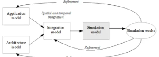
Our main objective is the modeling and simulation of an IMA platform. It consists in the description of the dif-ferent characteristics (software architecture, physical ar-chitecture, integration), to generate a simulation model able to verify the application constraints and require-ments. The proposed modeling approach is described in the figure 9. It consists of three modeling levels: applica-tion model, architecture model and integraapplica-tion model.
Figure 9. Proposed modeling approach
The application model describes the avionics applica-tions in term of communicating partiapplica-tions across logical communication ports and APEX channels. It also de-scribes the embedded functions embedded onto the par-titions.
The architecture model formalizes the description of an IMA platform architecture in terms of physical compo-nents (execution modules, sensors, actuators, ...) linked in heterogeneous networks.
The integration model describes the mapping of the ap-plication model onto the architecture model: spatial allo-cation of the partitions onto the execution modules and the APEX channels on the AFDX ports, and the temporal al-location of partitions and modules (MAF) and the virtual communication links (BAGs, SMAX).
The auto-generated simulation model is obtained from the integration model which is capable of driving the per-formance of the loaded IMA architecture. with respect to different communication metrics (end-to-end communica-tion delay, jitters, messages loss, ...)
The generated simulation model can be used to evalu-ate the performance of application and architecture mod-els. Moreover, we can use these results to fine tune the parameters defined in application and architecture model and re-generate the simulation model.
This iterative process can help in early design phase to decide optimal parameters for the IMA architecture. We are developing such a tool and initial results are encourag-ing.
5. Conclusion
In this paper we have presented the complexity of com-munication delays, analysis in the context of IMA archi-tecture (impact of the multiplexing jitter and the commu-nication in sampling and queueing modes, influences of source and destination execution periods and influence of the choice of the logical communication channels).
A deep analysis of those influential parameters requires a simulation tool able to consider the random aspects (off-sets of the modules and networks, tasks execution dura-tion, communication delay, ...).
The ongoing research covers the modeling approach of such an IMA architecture according to three levels (ap-plication, architecture, integration) and aims at generating a simulation tool that can be used to calculate the end-to-end communication of modeled software and physical architecture.
References
[1] M. Lauer and al. : Latency and freshness analysis on IMA systems.ETFA 2011, Toulouse, France, Sep. 2011. [2] Aeronautical Radio Inc. ARINC 429, ARINC specification
429-ALL: Mark 33 Digital Information Transfer System, 2001.
[3] F. Martin and C. Fraboul : Modeling and Simulation of Integrated Modular Avionics PDP 1998, Madrid, Spain, January 1998.
[4] Aeronautical Radio Inc. ARINC 651, Design Guidance for Integrated Modular Avionics, 1991.
[5] Aeronautical Radio Inc. ARINC 653, Avionics Application Software Standard Interface, 1997.
[6] Aeronautical Radio Inc. ARINC 664, Aircraft Data Net-work, Part 7: Avionics Full Duplex Switched Ethernet (AFDX) Network, 2005.
[7] M. Lauer and al. : Analyzing end-to-end functional delays on an IMA platform. In Proc. of the 4th ISoLA’10, Herak-lion, Greece, page 243-257. Springer-Verlag, 2010. [8] J. Javier Gutiérrez and al. : Response time analysis in
AFDX networks with sub-virtual links and prioritized switches. JTR’12, Santander, Spain, January 2012. [9] A. Choquet-Geniet and E. Grolleau : Minimal
schedula-bility interval for real time systems of periodic tasks with offsets. Theoretical of Computer Sciences, vol. 310, pp. 117-134, 2004.
[10] H. Bauer and al. : Worst-case delay analysis of an in-dustrial AFDX network DATE 2011, Dresden, Germany, Mars 2013.
[11] X. Li and al. : Existing offset assignments are near opti-mal for an industrial AFDX network RTN 2011, Porto, Portugal, July 2011.