CONSTRUCTION AND CALIBRATION OF A STANDARD PILE by
St.
OF TECHNO1 0JUN 6
1958
LIeRARS
WILLIAM FRANCIS REILLYB.S., United States Military Academy (1952)
SUBMITTED IN PARTIAL FULFILLMENT OF THE REQUIREMENTS FOR THE
DEGREE OF MASTER OF SCIENCE at the
MASSACHUSETTS INSTITUTE OF TECHNOLOGY May 26, 1958
Signature of Author
Certified by . . . ..
Signature Redacted
..0
0 S .00-. .0....*... .. .a0 *Department oChemical Engneering, May , 1958
Signature Redacted
0.0 .0 ... . w 0 ...C C 0 ... ..0 0 .Thesis Supervisor
Accepted by... * . . . .. . .. . ... . .0 .. . .
Chairman, Departmental Committee on Graduate Students /
ABSTRACT
"CONSTRUCTION AND CALIBRATION OF A
STANDARD PILE" by
William Francis Reilly
Submitted to the Department of Chemical Engineering on May 26, 1958, in partial fulfillment of the requirements for the degree of Master of Science.
The MIT Standard Pile is described and calibration procedures and results are discussed.
A determination of relative source strengths of five Pu-Be neutron sources is made. Spatial evaluation of thermalization in the pile is followed by calculation of diffusion length and Fermi age. Results of these calculations are used in determin-ing the flux and slowdetermin-ing down density distribution with a point source of fast neutrons in the pile.
Thesis Supervisor: Title :
Theos
J.
Thompson Associate Professor Nuclear EngineeringPage
I. TABLE OF FIGURES AND TABLES... 1
II.
ACKNOWLEDGMENTS . . . 2III. INTRODUCTION . . . 3
IV. DESCRIPTION OF PILE .. .. . .. ... . 4
V. EXPERIMENTAL PROCEDUR. .. . .. .. . . . 8
VI. SOURCESTRENGTH.. ... . .. .. ... .. . 14
VII. THERMALIZATION . .. .. . .. . . .. . .. . . 18
VIII. DIFFUSION LENGTH .. .. .. . . .. . . . 19
IX. FERMI AGE . . . 27
X. STANDARDIZATION . . . .. 33
XI.
CONCLUSION . . . 39APPENDIX A - Foil Locations, Activations, and Corrections. . . . * . . . . * * . . 41
APPENDIX B - Data for Relative Source Strength Determination . . . . * 44
APPENDIX C - Pile Weight and Volume . .. . . . . .. . 47
APPENDIX D - Foil Weights and Thicknesses . . . . . .. 48
1.
I. TABLE OF FIGURES AND TABLES
Page
Figure 1 Sketch of North Face of Pile 7
Figure 2 Cadmium and Indium Cross Sections 8
Figure 3 Plot of Diffusion Length Data 24
Figure 4 Plot of Fermi Age Data (Slope Method) 29
Figure 5 Pu-Be Source Spectrum 31
Figure 6 Plot of Fermi Age Data (Integral Method) 32 Figure 7 Plot of Thermal and Epithermal Activity 37
Figure A-1 Five Source Positioning 43
Table 1 Source Strength 15
Table 2 Thermalization 18
Table 3 Weight Factors for Evaluation of Diffusion Length 22 Table 4 Results of Diffusion Length Evaluation 23
Table 5 Values of A and rn 34
Table 6 Values of Cn, f, andr n, 35
II. ACKNOWLEDGMENTS
The author's most sincere appreciation goes to the Corps of Engineers, U. S. Army, for making it possible to pursue graduate study in nuclear engineer-ing at M.I.T.
Invaluable assistance in preparation of this work was rendered by Dr. T.
J.
Thompson, thesis advisor. Thanks are also due Dr. I. Kaplan for his advice and to Capt.J.
G. Waggener, Lt. E. R. Heiberg, and Lt.J.
V. Foley who freely applied their structural talents toward some of the more tedious aspects of the preparation.It is impossible to completely express my gratitude to my wife, Peg, for her patience, encouragement, and laundry services as well as for her tireless and excellent preparation of this thesis in its final form.
3.
III. INTRODUCTION
Because of its very fine nuclear and structural properties, graphite has enjoyed a prominent position among materials employed in neutron research and reactor production. An extremely valuable laboratory tool based on these
desirable properties - the standard or sigma pile - can be constructed to study
the diffusion and slowing-down processes and to calibrate foils, fluxes, and neutron sources.
The construction of the two types of piles is essentially the same. They derive their names from the type of experiments that are performed on them. The standard pile is constructed of a material of known nuclear constants, hence the epicadmium and thermal flux can be calculated throughout the pile as accurately as the source strength is known. In the sigma pile the neutron distribution is measured and calculations of the nuclear constants are based on observatiojn (1).
This work is concemed with the design and construction of the MIT standard pile and the measurement of the plane of thermalization, the diffusion length, and the Fermi Age of neutrons from Pu-Be sources in it. Relative source strengths of the five neutron sources available are measured. Finally, spatial distribution of the slowing down density is found, and using this as a source term in the neutron diffusion equation, an expression for the absolute flux in the pile is derived.
IV. DESCRIPTION OF PILE
The MIT standard and sigma pile was constructed during July and August 1957, in the Nuclear Engineering Laboratory. It consists of a cadmium covered 60" x 60" x 86.5" graphite block on a concrete pad.
The concrete pad foundation reduces the possibility of contamination or wetting of the pile and affords a level base for it. Felt carpeting was placed on the pad and a sheet of 20 mil cadmium rests on top of this.
Graphite for the pile came in milled bars of rectangular cross section and varying lengths. Cross section dimensions varied from 2 3/4" to 3 3/4". Because of the graphite demand of the MIT Reactor, short stock was used as much as possible. Each bar was weighed prior to its placement in the pile so that density corrections could be made on diffusion measurements. A record of these weights and layer volumes is included in Appendix C. The computed pile density is 1.662 gm/cm3
With the exception of the fifth layer (diagonally placed stringers) construc-tion consisted of stringers in adjacent layers being cross stacked for purposes of stability. All channels into the pile are plugged with removable graphite dowels to maintain uniform density of the pile. All stringers with channels in them have been sanded down to allow removal in the event a neutron source becomes
5.
The first three layers are of solid configuration. This affords over a foot of graphite between the bottom of the pile and the source layer to prevent end effects from being felt in foil activation. The fourth layer is the first source layer. It consists of thirteen stringers with 1 1/4" center holes in them to hold neutron sources. Practically any source configuration can be obtained in this layer. The fourth stringer with a source channel on either side of the central stringer is set at a precalculated distance of half the half-width plus extrapolation distance to allow two or four matched-source diffusion length measurements with major harmonic cancellation (8). These
stringers are removable and are spaced by removable graphite shims in the event that their position needs to be altered.
The fifth layer is a source layer with diagonal channels to provide more flexibility in source placement. When facing the channels of the fourth
source layer, the diagonal channel on the viewer's right is a through channel. The channel that is perpendicular to the through channel has tiny air holes to the center of the through channel to permit evacuation of the graphite plugs in it by a vacuum device.
The sixth through the tenth layers are solid except for the central stringers which have channels.
The eleventh through twenty-third layers alternate in configuration with the even numbered layers consisting of solid graphite with a central channel. The odd numbered layers are solid graphite and have a central drawer stringer
with milled 1" circular dishes on top to hold foils. These drawers project beyond the 60" pile and are marked to indicate the correct position to place the sixth dish in the center of the pile.
The top layer of the pile is solid graphite. Figure 1 shows the pile layout and dimensions.
A 20 mil cadmium cover surrounds the pile and channels are accessible through flaps in it. A removable cadmium cover is hung on the projections of the drawer stringers. This cadmium serves to curb dust contamination of the pile and prevents the re-entry of thermal neutrons into the pile thus affording an isolated diffusion medium unaffected by exterior conditions or objects. Fast neutron re-entry is minimized by placing the pile away from walls and in a high ceiling room.
7r~
7. 91 9.30
1,
I I I I I I12
1 1 .. 1 -- 70c2 - 1 -7 P- 5 79T4
I
I
S
TTTTTTNortl
FeO
Sca/e:
I=O
177 1 ~1-j
T7o
Vie
w
Cianne(
In'rtersection
Position2
IL holes /h/)\7
7
I7
4 - I ~-,-
-
i
A 9E.-4Fl(7-7L)RE I
TT I I I I 1-.:]:Pos;rzQm Zcm--t
T I I 1 -1 1V. EXPERIMENTAL PROCEDURE
The method of foil activation was employed for measurements on the pile. Thin, 3/4" diameter circular indium foils (particularly good for relative flux measurements), with and without cadmium covers, were placed in the pile at various distances from a source of neutrons. Foil activation based on the 1.458 e .v. resonance of indium and the cadmium cut-off of thermal to approximately .5 e.v. neutrons was measured by means of a Geiger tube and scaler. N
Basically, the activation of bare indium foils is due to thermal and epithermal neutrons. When the indium is covered by cadmium, the thermal neutrons are absorbed by the cadmium and the indium activity is caused by the epithermal flux only.
10,000 Cd , U) z C10o00 - In 100-U) U) o -4 o 0 -J 0 0.01 0.1 1.0 10 100 NEUTRON ENERGY, EV FIGURE 2
9.
Figure 2 shows the cross sections of cadmium and indium. It can be seen that the ideal theory of activation just outlined must be some-what modified to account for some indium resonance neutrons suffering capture
in the cadmium. In addition to this, thin cadmium covers do not act as thoroughly "black" thermal neutron absorbers.
Martin (5) has published correction factors to be used with cad-mium covered foil measurements in the determination of activation due to thermal and epithermal neutrons. For the foils used in this work, they are:
Aepi: 1.09 2 (Acd - .OO2AB
and
A - AB - 1.09 Acd (2)
where A is foil activation and the subscripts refer to: epi due to epicadmium neutrons
th due to thermal neutrons B of bare indium foil
cd of indium foil exposed with a cadmium cover
Weights and thicknesses of foils employed may be found in Appendix D. The decay constant of indium is .01282 min.~1 and all foils were exposed to the neutron flux for approximately twenty hours, so for all practical purposes saturation activity was obtained.
The formula for determining saturation activity from foil counts is (3):
A ANe AT (3) sat
(1 -e-A tl(1- -.At2)
where: T= time from removal of flux to beginning of count. (This was always at least 3 minutes to allow the 13 second half-life activity to decay and thus consistently measure the 54 minute half-life activity.)
t i time of flux exposure
t 2- time of counting. (This was always 5 minutes.)
N: the number of counts during t2 less background.
A the decay constant (.01282 min.- for indium). When all values are substituted in this, it becomes:
A = .21 N e (4)
sat
For simplicity, Asate-3 : N has been used throughout this work since all .21
foils were counted 3 minutes after their removal from the flux.
Counting was done on a standard geometry in a lead cave. The procedure consisted of an initial background count. This was submitted to a Chi-Squared test to check counter reliability and each series of readings was followed by a background count.
During the experimental part of the work, Geiger tube 73T6 was used. Dead time was calculated for it by the two source method (10) and counts were corrected for this dead time
by-N: n (5)
11.
where: N true count
n ~ observed count
T dead time of the tube
(T was 450 microseconds or 1.5 x 10⁻⁶ when n was in counts/5 minutes) When measurements obtained at different positions by different foils are to be used in the same calculation (e.g. diffusion length) some corrections must be taken into account to relate all readings to those of a standard foil.
The activity of a foil, in the first approximation, is proportional to its weight. However, this difference in weight between foils, and hence thickness, breeds error in itself. Four corrections must be considered to
strictly obtain flux values at a point. These are due to flux hardening, flux depression, self-protection and obliquity(1).
Thermal flux hardening is caused by preferential absorption of low energy neutrons in a 1/v absorber near the surface. This causes the average energy of the Maxwell-Boltzmann distribution to increase in the interior of the foil and thereby effectively decreases the cross section of the indium more for thicker foils.
Flux depression is due to the presence of an absorber in the flux region. Hughes has worked out a theoretical correction for a spherical shell foil. Bothe presented a theory for correction of plane 1/v foil readings and this was verified by KLema and Ritchie (6).
A self-protection correction must be applied to foils that are
thick enough to reduce the transmission of flux (e -Na-x) to their centers
by an appreciable amount.
An obliquity correction is best obtained experimentally. This is based on the fact that in an isotropic flux, the effective foil thickness, and hence the previous corrections, will be a function of obliquity.
In the original work, all foils except two (5 and 7) were of suf-ficiently uniform thickness to warrant no corrections, except for weight, on their relative readings. The two heavier foils were employed near the source where there is a substantial epithermal flux and, because of the many
resonance peaks of indium in this energy range, an experimental correlation of light and heavy foils in the same flux was attempted. This was done
by comparing readings obtained by averaging five 5 minute decay time
corrected counts on different foils placed in the same position. Values obtained by this method tended to over-correct for thickness since corrected heavy foil activation readings fell below a smooth curve plotted through activation points of thin foils.
When this effect was observed, a rerun of the experiment was made with thin foils only (corrected for weight) and good results were obtained.
The pile is comparatively small in the horizontal directions. This leads to a fairly large leakage from it, so it was decided to employ the
13.
five neutron sources as a point source to attain a maximum flux in determin-ing the pile parameters.
Errors quoted in this work are probable errors or .6745 times the standard deviation.
Foil locations, activations, and corrections for the determina-tion of Secdetermina-tions VII through X are listed in Appendix A and data for Secdetermina-tion VI are in Appendix B.
Foil #14 was chosen as a standard (weight: 153.5 m.g.) and foil weight corrections were based on it. (See Appendix D.)
VI. SOURCE STRENGTH
Prior to 1954, large international and interlaboratory discrepan-cies in absolute neutron source strength calibration existed. These have now been resolved to within approximately / 5% and Hughes has suggested a "world's best value" agreed upon by several institutions (9). Work is being continued on reducing the difference.
It is of value to know the relative strength of sources used in one laboratory to permit matched source measurements with major harmonic cancellations. A check of these relative values was undertaken on the available sources by exposing four foils to them in proximate locations in the pile. Since the same foils were exposed each time in the same geo-metrical location and any thickness correction would be identical for each exposure, their activation was proportional to the source strength.
Five Pu-Be neutron sources marked M-51, M-52, M-53, M-54, and M-55 were available for this work. They were in 1.02" x 1.6" tantalum and stainless steel cylinders. Published. information on these sources is listed in the first four columns of Table 1. Calibration listed in column 4 was performed at Mound Laboratory prior to shipment to M. I. T.
The usual procedure was followed in treating the raw data by correction for counter dead time and background. The corrected activation of each foil for each source was then reduced to a ratio with respect to the corresponding reading with the M-55 source for
Q,
and an average sourceTABLE 1 Source Gms Pu M-51 15.99 M-52 16.03 M-53 16.02 M-54 15.92 M-55 16.09 neutrons Gms Be Q sec(xj10 7.91 1.65 7.92 1.63 7.9 1.64 7.88 1.5 7.96 1.67
QI(x10
6 1.649 /.007 1.654 /.008 1.662/.007 1.470/.007 1.67/0 Q2(x106) 1.646/.007 1.651 /.007 1.659 /.007 1.431 /.006 1.667 /.005 Q3(x106) 1.644/.005 1.651 /.004 1.658 /.006 1.433 / .018 1.667/.003( See text for explanation of Qi, Q2, and
Q3
)16.
for Q2 and
Q3.
This was done to give each reading equal weight. The four ratios for each source were then averaged and compared with averages derived from published values. Results of this comparison are tabulated in detail in Appendix B.Q,
is based on aQ
of 1.67 x 10⁶ neutrons/sec. for M-55.Q2
is based on a source of 1.618 x 10⁶ obtained by averaging published values in column 4. Both are unweighted averages, and errors are the result of propagating statistical counting errors.Q3
is a weighted average based on the 1.618 x 10⁶ source and the listed error is the larger of the errors based on internal and external consistency.The four foil ratios for each source used in the determination of Q2 and Q3 were checked for internal and external consistency. Results were very good with the exception of source M-54 (Re/Ri
=
4.7 for thissource). There is no definite value for this ratio, but it should not be greatly different from unity. Re/Ri depends on the actual scatter of points from the average value and the predicted uncertainty of the same point (12).
Details of the internal-external consistency calculations are also listed in Appendix B.
Pu-Be sources are comparatively new and are superior to Ra-Be and Po-Be sources in some respects. They have a very long half life (2.2 x 10⁴ yr.) and a low gamma background. They are more inexpensive than Ra -Be and, being an intermetallic compound, the spectrum does not
17.
depend on the grain size as it does in Po-Be sources. The spectrum is similar to that of Ra-Be and Po-Be and is investigated further in Parts IX and X (2).
VII. THERMALIZATION
The cadmium ratio (Rcd) is a ratio of bare foil activation to activation of a cadmium covered foil. Although it neglects the fine corrections (5) it is approximately a ratio of thermal plus epithermal flux to epithermal flux at a point. Values of Rcd in this pile show larger statistical errors due to low counting rates as they increase, but it can be assumed by inspection that the flux is well thermalized at the number 12 foil position or 103.3 cm. from the source. The following values for Rcd were determined at z cm. from the source:
Layer 3 4 5 6 7 8 10 12 14 z 17.45 25.75 34.0 42.2 51.1 65.4 84.5 103.3 121.8 Rcd 5.088 5.644 7.599 8.298 12.792 20.841 74.000 94.813 Qc error /.042 /.057 /.087 1.124 1.262
/
.799 /13.5/
32.6 re- 4.845 5.439 7.097 8.784 11.704 20.387 45.380 137.44 check TABLE 2A recheck for consistency was run and the values are listed in the fifth line of Table 2. Errors are the same order of magnitude.
19.
VIII. DIFFUSION LENGTH
In a diffusion media far from sources and boundaries, the thermal neutron density satisfies the diffusion equation:
V2n - K2n 7 0 (6)
where K is the inverse of the diffusion length, L, of the media. With the origin of coordinates at the neutron source and the assumption that n is the product of x dependent, y dependent, and z dependent functions, the solution of interest is (4): n-C e-bjkz(7 (0, 0, z)- j1 k: 1
jk
(odd) (odd) where b K2 2 0 k2) (8) jk a(a is the extrapolated pile width)
Equation (7) consists of a fundamental term (j k 1) and a series of harmonic terms each of which falls off exponentially with a relaxation length equal to (bjk) -. Inspection of equation (8) indicates that higher harmonic terms fall off more rapidly than the fundamental term and that
eventually at large z the latter makes virtually the sole contribution to the flux (4).
If harmonic corrections (important at low values of z) and end corrections (important near the top of the pile) are applied to a semilog plot of thermal flux activation versus distance from the source along the
z axis, the ensuing line will be the fundamental term and its slope will
--be -b 1 . By a least squares fit of a line to the experimental points, b1 1
can be determined, and K, and thence L, can be calculated from equation (8).
An expansion of equation (7) through the 3, 3 harmonic results in:
n(0, 0, z) Ge- zl1 /b 1 ebz(13z e3Z 33
Higher harmonics are negligible. It can be seen that if the activation is divided by the quantity in square brackets (the harmonic correction factor), harmonic deviations from the fundamental mode can be omitted.
The fundamental z dependent function employed in evaluation of equation (7) is actually of the form:
SAe -bz [ - e2bil(c-z (10)
where c is the extrapolated height of the pile. The quantity in square brackets is the end correction term and is near unity except as z approaches c. If the experimental activity is divided by this end correction term, deviations from the fundamental mode near the top of the pile are omitted.
Since the bjk terms and the corrected activation are mutually dependent, this procedure demands an iterative process which, when applied a sufficient number of times, will cause the line slope and therefore the diffusion length to converge to the required accuracy.
The transport mean free path was calculated to be 2.64 cm. for this density graphite. By adding (2) (.7lAtr) to the physical width of
21.
the pile, one obtains an extrapolated width of 156 cm. and equation (8) becomes: b 2 K
/
.000811 (11.1) 2 2 b b K2/ .004055 (11.2) 13 31 b2 K2/
.007300 (11.3) 33The constant terms in these equations have the physical significance of accounting for leakage from a finite medium.
The assumed transport mean free path was also used in determi-nation of c in equation (10). With the origin taken at the source, c is 188.4 cm.
Activation in foil positions 13-20 was used in diffusion length determination. Since there was no Acd for any of the foils, bare indium foil activations, corrected for foil weight, were employed.
The value of the slope of the semilog plot of Ath versus z is obtained by a least squares fit from:
b (w= z1 )wi lnAi) - (wi)(twiziln Ai) (12)
(4wi ) 4wizi2) - (Lwiz1)4
where w is the weight factor. The numerator of this equation is a small difference of large numbers, and because of the sensitivity of L with respect to b i, extreme care must be taken in evaluation of it.
The Ath versus z plot is concave downward and a weighted evaluation of bi will be less than an unweighted one. The usual statistical
2
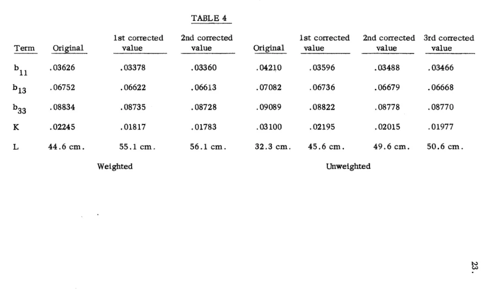
practice of weighting points proportionally to A th for a logarithm plot was used to obtain one value of L. (Values of weight factors are listed in Table 3.) However, Chernick and Kaplan (7) recommend an unweighted evaluation of L because systematic errors are greater for small values of z and hence tend to negate the low statistical errors. For comparison, an unweighted evaluation was also made. This comparison is shown in Table 4. Foil Position z (cm.) w Foil Position z (cm.) w
13 107.8 200.0 17 144.7 28.6
14 121.8 162.5 18 158.7 10.1
15 126.3 130.0 19 163.2 6.2
16 140.2 43.3 20 177.1 1.0
TABLE 3
(The computed weight factor in position 13 was roughly halved since it was nearest the source and more subject to systematic error.)
Figure 3 is a plot of activations and corrections for the weighted calculation of L. The combined effect of harmonic correction factor and end correction term application can be easily seen.
The values listed in Table 4 are for the graphite as is. Compari-son is generally made at a graphite density of 1.6 gm. /cm.3 When the
diffusion length is corrected to this density it becomes 58.2 cm. for the weighted value and 52.5 cm. for the unweighted value.
A refinement in theory that causes a slight correction to the above
TABLE 4 1st corrected 2nd corrected value value .03378 .03360 .06622 .06613 .08735 .08728 .01817 .01783 55.1 cm. 56.1 cm. Original .04210 .07082 .09089 .03100 32.3 cm. 1st corrected 2nd corrected value value .03596 .03488 .06736 .06679 .08822 .08778 .02195 .02015 45.6 cm. 49.6 cm. 3rd corrected value .03466 .06668 .08770 .01977 50.6 cm. Unweighted Term b 1 b13 b 3 3 K L Original .03626 .06752 .08834 .02245 44.6 cm. Weighted C.&3
L I
U
LA [ -~ f-i--, %t Ac~I\
4-M
-It
,
4
j
OR IGIx rege
y7
Kg
v2-a' T M I -, 0I
.4
//0 /20 /30 61! /#0 150 /60 3-4---.
/70 /80 190 rc M)8.0
irAh
z
ri
I I I lit-I + 9 I25.
source, as in Equation (6), a fast source theory is used. The basic equations then become:
2 n - 22 0 (13)
L D
and g2q = dq (14)
dt
where t is the age to thermal.
The resulting correction is fairly insensitive to values of L but more sensitive to t. An average to (calculation in Part IX) for the Pu-Be sources is 378.5 cm.2 This amounts to a correction of -. 16 cm. on the weighted value of L and - .15 cm. on the unweighted value or 55.9 cm.
and 50.4 cm., respectively, for the weighted and unweighted diffusion lengths. More recent work at Brookhaven by Kouts, et al utilizing a thermal column as a plane source has resulted in higher values of L than were
obtained with an in-pile source as described in reference (7) and performed here in the unweighted calculation.
Graphite used in the MIT standard pile was purchased from Brook-haven National Laboratories, but the type is unknown. By assuming a known scattering cross section of 4.8 barns for graphite and utilizing the fact that the pile is a weak absorber, an absorption cross section may be obtained from:
1a
-4 -1 This results in a macroscopic absorption cross section of 2.8 x 10 cm.
-4 -1
(weighted) or 3.44 x 10 cm. (unweighted).
A calculated absorption cross section for this density graphite using a microscopic cross section of 3.2m.b., as is listed in BNL 325,
-4 -l
is 2.672 x 10 cm. The effect of impurities in the graphite can be detected by a comparison.
Both weighted and unweighted results have been quoted in this section and in Section X for comparison, but for the sake of consistency with other published values, it seems that the unweighted results are more valid.
27.
IX. FERMI AGE
The slowing down of neutrons from birth energies to thermal energy can be approximated as a continuous process in moderators other than those containing very light nuclei. This Fermi Age treatment applies to carbon.
The Fermi Age equation is: 2
7q =on_ (16)
at
where q is the slowing down density and t is the Fermi Age. The solution of this equation for a point source of fast neutrons in an infinite medium is:
2 -z /4t q ) Se (17) (z,(t) 4 17t)3/2 2 or ln(q) : -C z /4t (17.1)
The slowing down density at indium resonance energy (1.458 e.v.) is proportional to the activation of a cadmium covered indium foil as modi-fied in Equation (1). When the logarithms of these values are plotted versus
2
z , the slope of the resulting line is seen to be -1 where ti is the age to
indium resonance.
There is an upward deviation from the ideal line at both ends of the plot, so only the central portion is used in this determination. The
devia-tion at the end near the source is caused by capture of the relatively large number of neutrons of energies exceeding 1.458 e .v. in the indium resonances
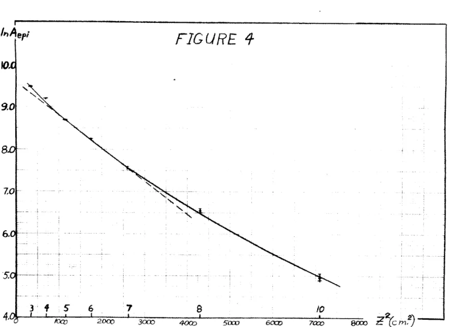
achieved and the activation (caused by the neutrons of resonance energy in the Maxwell-Boltzmann Distribution) falls off exponentially, as was shown in the calculation of diffusion length, rather than as a Gaussian. For this reason, positions 5-7 were used and a slope was obtained by a least squares fit as outlined in Part VIII. This resulted in a value of 322 cm.2 (See Figure 4).
Another less sensitive method of determining ti can be accomplished by establishing the maximum point on a plot of qz2 versus z. By multi-plying Equation (17) times z2, differentiating, and equating to zero,
2
d(qz) Ce-z /4t(2z - 2z3 ) :0 (18)
dz 4t
and we find that z2
=
4t at the maximum point.This method gives good agreement with the above value of ti (see Figure 6), but because of the difficulty of graphically locating the exact maximum point, it cannot be relied on for accurate evaluation. In this case, the maximum point occurs at about 36 cm. and ti
=
324 cm. 2 Another graphical method stems from the second spatial moment of the slowing down density. This is:2
2~~z 44 - z /4t
Z = _zdz : z Ze dz = 6t
(19)
z qdz ,J*zle-z/4tdz
By a graphical integration of Aepiz4 and Aepiz2, ti was found to be 359 cm.2 (Figure 6).
FIG
URE
4
NJ 7 8 /0 2OO2~ 402 Scw 7cco~80
42(c
I*A
e
9.0
8L
7,0 6.0! 5c 4Zc~3*f
I a5*
i6
I 20,00 3000 4OCo 5aw 7C:C30.
Since the Pu-Be sources are not monoenergetic but have a spectrum as indicated in Figure 5, the above calculated value of ti is from an "effective" energy of this spectrum to 1.458 e.v.
By using the Fermi Age integral equation with first and last flight corrections, a comparison (7) has been made with some earlier work by Fermi, et al, on the correlation of ti with initial neutron energy. The agree-ment is good up to 4.2 Mev and gives an "effective" energy for these sources of 1.7 Mev.*
A large number of the collisions undergone in the slowing down process are encountered by neutrons of energy less than indium resonance
energy. A correction (t ) must be added to t. to obtain the total age to
1-0 1
thermal. This is calculated by the Fermi Age integral equation,
t fD du =Du (20)
1-0 (20
2
(since 3 s is constant in this energy range) and is 56.6 cm. This results 2
in a t (age to thermal) of 378.5 cm. for the Pu-Be sources.
0
* This energy is merely based on t. Effective energy of the source as based on integration of the spectrum is 4.4 Mev and average energy is 4.2 Mev(2).
31. 12 -xio7 10-6
-z
o %Q= 1.75 MEV 7.5 MEV LEVEL 4 \ 0-1.25 MEV\j
\ 4.5 MEV LEVEL 0Q- 5.75 ME V \ GROUND STATE\ 0 I 0 2 4 6 8 10NEUTRON ENERGY, MEV
Energy distribution of the neutrons from Pu-Be
FIGURE 5
FIGLfE
L
Aep 14 12Mr
r
10 -- -- ---20 30 40 S0 60 70 80 90 /00 1,0 120 F (c u 0 /33.
X. STANDARDIZATION
It is possible to produce a flux that is known almost as accurately as the strength of the neutron source producing it. This flux may then be used as a standard for comparison with other measurements in the labora-tory. Briefly, this is done by first calculating the slowing down density, q, and using it as a source term in the neutron diffusion equation.
As was pointed out in Part IX, the Pu-Be sources are not mono -energetic, but have an energy spectrum over nearly 11 Mev. Because of this, it is not feasible to express q as a function of a single age as is done in Equation (17). Instead, the spectrum is approximated by blocks of neutrons of an average birth energy. This gives rise to a sum of Gaussian terms, dependent on the age to E of the neutrons, and the fraction of total neutrons within the block. The constants in this sum of Gaussians are generally evaluated by a least squares fit of the experimentally determined values of Ae, the form being:epi
Ap=fA e -Z2/rn2 (21) P n
The r's in this sum are Gaussian ranges and equal 2 r
It is common practice to use a sum of three Gaussian terms for this. Since there are an insufficient number of experimental points in this pile to permit a good least squares fit of six constants, the ranges were arbitrarily chosen and the constants, A n's, were fitted.
to that of Pu-Be sources (11). A three range approximation for Po-Be sources is known (7), and by a comparison of the spectra and the published values of ti versus birth energy, three ranges were arrived at for use in this fit. Results for Pu-Be sources in this pile are:
n An rn(cm) 4 1 l.1668x10 28 2 .6039x104 39 3 .0954x104 60 TABLE 5
A complementary equation for the slowing down density is: (22
q/Q = fn Cne rn (22)
n= 1
where fn is the fraction of the total neutrons in the nth block of the approxi-mated spectrum and Cn is given by:
Cn n
:4
a Yrrrn 2 expfTr ( ) (23)Jk 4a
(odd) where a is the effective pile width.
By combining the experimental evaluation of An with the calculated Cn, fn can be obtained from:
AnC
f n (24)
n - A/C / A
2/C2 / A3/C 3
When Equations (23) and (24) are combined with Equation (22) an expression for q in terms of
Q,
the source strength, is obtained.35.
By a solution of the neutron diffusion equation with the source term given by Equation (22) an expression for the thermal flux may be obtained in the form (1 and 3):
ny 4.66 x 10
3
f n = n
where the constant is 3/A a2, fn is given by Equation (24) and Fn is given by:
2
F: 2 e on/4Le
jk
1-erf( rOnJk e-zj 1/erf( r 26(odd)
(bj is defined in Equation (8)). The Gaussian ranges, ron, are extensions of the previously given rn's to thermal energy and are given by:
r on : r2 / 227.5 n (27)
for rn at indium resonance.
From Equations (23), (24), and (27), the following values were obtained: Cn -6 1 8.1873 x 10 .314 31 2 3.0272 x 10⁻⁶ .440 41 3 .8272x 10-6 .246 61 TABLE 6
By the use of these constants, Equation (2 the flux at any location along the z axis in the pile.
'n ron(cm)
5) can now be solved for (25) MMI - - 1. 1.. -- "VOMM"W --- --n .8 .8 .9
As an example and for a calibration point, foil position 4,
25.75 cm. from the source layer, was chosen. (See Appendix A for source positioning.) By evaluation of Equation (26) it was found that F1 = 28.78,
F2 - 20.87, and F3 = 10.48 (weighted value of L) and F1
=
27.52, F2= 19.93,and F3
=
9.96 (unweighted value of L). This results in-4
nv/Q = 9.70 x 10 (L
=
56.1 cm., z 25.75 cm.) (28.1) nv/Q = 9.26 x 10~4 (L=
50.6 cm., z 25.75 cm.) (28.2) By utilizing published values ofQ,
this gives a flux at foil position 4 of3 2
7.49 x 10 neutrons/cm. -sec. with five sources in the pile; calculated with the more reliable unweighted diffusion length (see section VIII).
Figure 7 shows the experimental distribution of activation from resonance and thermal neutrons. (Experimental activation was corrected by Equations (1) and (2) ). Since Ath is proportional to nv and Aepi is pro-portional to q, flux and slowing down density at any position along the z
axis can be readily obtained from the graph if their values are known at one point.
As an example, consider the 5 source placement giving a flux of
3 4
7.49 x 10 at z = 25.75 cm. Figure 7 gives a value of 4 x 10 for A at this point. If the value of the flux at z = 70 cm. is desired, an Ath of
1.09 x 1O4 at 70 cm. is read from Figure 7 and the ratio of the Ath values is proportional to the ratio of the fluxes. This gives a flux of
FI2UFRE
7
31 4 -6 73 4 5 Oa 50 60 70 80 90 /00 /0 Z (C I.) 37. 41 /0 20 30 40 - --, ~ ~ - i...
Tmomumo
38. (nv)7 0=
(nv)2 5.7 5 (Ath)70 (Ath)25.75 - 7.49 x 10 3 at z : 70 cm. 1.09 4.00 = 2.04x 10339.
XI. CONCLUSION
Work on this thesis has included the design and construction of the M.I. T. standard pile. Relative strengths of available sources were then calculated by activation of four foils and a statistical analysis of these activations. The nuclear constants of the pile were investigated, and finally the pile was calibrated to produce a flux dependent only on neutron
source strength.
Diffusion length measurement was seen to be very sensitive to changes in line slope as plotted in Figure 3. The most reliable value was taken to be 50.6 cm. This was obtained by an unweighted fit of a line to experimental points. Since recent work at Brookhaven has indicated that this method may give low diffusion lengths, the fast source correction was not subtracted from 50.6 cm. for further work.
The comparison of thick and thin foils in the epithermal region of the pile appeared to be valid and reproducible, but experimental points corrected by this method fell below a curve fitting all other points. Because of this, thin foils were substituted and a rerun was made. This led to an excellent smooth curve fit of the data (see Figures 4, 6, and 7).
Relative source strength calculation appeared to be internally and externally consistent with the exception of source M-54. Published strengths list source M-51 as the second strongest of the group. Results of this
analysis located it as the second weakest source. The order of strengths of the other sources was preserved.
The value of ti in Part IX is strictly applicable to monoenergetic sources only, however similar determinations for other polyenergetic sources were found in the literature (4 and 7). A value of 330 cm.2 is quoted for Po-Be sources (4). This was found by a slope measurement over a range
comparable to that used in Figure 4 and is in extremely good agreement with 2
the calculated value of 322 cm. for Pu-Be sources found in Part IX when the two very similar spectra are compared.
However, it appears that a more accurate value of age can be
obtained from the numerical integration method. This is due to the assump-tion that the upward deviaassump-tion of the curve from the dashed line beyond z : =2700 cm. 2 in Figure 4 is entirely due to thermalization. The devia-' tion is partially caused by slowing down of neutrons in the higher energy part of the source spectrum. A correction for this would cause the slope of the line to decrease and ti to increase towards a value obtained by the inte-gration method.
2 The resultant age to resonance by this method is 359 cm. and
2
to thermal is 415.6 cm. This gives an "effective" source energy of 2.3 Mev. The correction to diffusion length is again minor: -. 26 cm.
APPgNDIX A
Foil Locations, Activations, and Corrections
Foil Position 13 14 15 16 17 18 19 20 z cm. from Source 107.8 121.8 126.3 140.2 144.7 158.7 163.2 177.1 5 min. Raw Count (4 r) 2447 /33 1624 /27 1381 / 25 950 /21 742/ 18 534 /16 420 /14 261 /11 Corrected for Dead Time 2456/ 33 1628/ 27 1384 /25 951/21 743 /18 534/ 16 420 / 14 261/ 11 Corrected for Background 2315 /33 1487 /27 1243 /25 810 /21 602 /18 393 /16 279 /15 120 /12 Corrected for Foil Weight 2602/ 37 1612/ 30 1442/ 29 832/ 22 677 /21 402/ 17 314 / 16 127/ 12
5 Sources as a point, bare foils (Utilized in diffusion length calculation) Foil 1 13 8 12 9 15 3 16
Foil Position 3 4 5 6 7 8 10 12 14 z cm. from Source 17.45 25.75 34.0 42.2 51.1 65.4 84.5 103.3 121.8 A d 12062 j 80 8958 /70 5596/55 3475/ 45 1825 /33 664 / 23 142/ 15 25/12 0 AB 58444 /180 48722
'164
39717/147 30523/
129 21360 / 107 13537 / 85 6444/ 56 3432/ 44 1629 / 21 A A. (Corrected by Eq (1 and(2) 45296 38958 33617 26735 19371 12813 6289 3437 1629 13044 9676 6025 3728 1946 696 141 20 0Due to the large error in Acd of foil position #12, it was not used in calculations. (Utilized in Thermalization, Fermi Age, and Standardization Calculations)
A epiz2 (x 106 3.9719 6.4162 6.9649 6.6388 5.0814 2.9769 1.0068 A eiz4 (x 109) 1.2094 4.2546 8.0514 11.8224 13.2686 12.7328 7.1889 0 0
43.
APPENDIX A (Continued)
For all 5-source measurements, the central three source channels were used with three sources being placed in the middle channel. Figure A-1 schematically shows the positioning.
U ~ ),~K~m
M'2
M51
M54
P155
H53
North
Face
FIGURE A-1I
Data for Relative Source Strength Determination Source Foil M-51 M-52 M-53 M-54 M-55 Corrected Activity 12186 /76 8540/63 7693/60 7450/59 12268 /76 8558/63 7888/61 7309 /59 12338 /76 8491 J63 8091 /61 7268/58 11127/73 7524 /59 6828/ 57 ' 6591/56 12400/54 8715 / 45 7926/43 7336/42 Ratio with M-55 .9827 / .0075 .9799~/ .0088 .9706
/
.0092 1.0155/.0099
.9894 / .0080 .9820/.0088
.9952~/ .0094 .9963 /.0099 .9950 / .0075 .9743 /.0088 1.0208 / .0095 .9907/.0097
.8973/.0071
.8633 /.0081 .8615/.0086
.8984 / .0092 Average Ratio .9872/
.0045 .9907/.0045
.9952/.0045
.8801/
.0041 Relative V ngth (x10 (Q 1.649 / .007 1.654 / .008 1.662/
.007 1.470 / .007 1.67/0APPENDIX B (Continued)
Ratio with Source Foil Average
M-51 5 6 8 9 5 6 M-52 8 9 M-53 5 6 8 9 5 6 M-54 8 9 5 M-55 6 8 9 1.01017 1.0208/ 1.0010/ 1.0360/ 1.0169 7 1.02307 1.02647 1.0164/ 1.0227/ 1.0149,/ 1.0528 / 1.0107/ .9223 / .8094/ .8885/ .9166 / 1.0279/ 1.0417/ 1.0314/ 1.0202/ .00685 .00815 .00845 .00896 .00685 .00816 .00862 .00895 .00685 .00815 .00864 .00880 .00654 .00758 .00796 .00841 .00524 .00628 .00653 .00683 Average Ratio 1.0170 /.00405 1.0207 / .00410 1.0253
7
.004087'
.8842 .00383 1.03037.00313
Relative. Strength (x106) (Q2) 1.6467.00655
1.651 .00664 1.6597.00660
1.4317.00619
.7'
1.667 .00506 P 1.710 1.210 1.123 1.000 1.707 1.202 1.078 1.000 1.650 1.167 1.038 1.000 1.655 1.232 1.116 1.000 1.699 1.182 1.092 1.000 Weighted Average Ratio 1.0158 1.0203 1.0248 ,8858 1.0304 Relative Strength (xA6 (Q3) 1.644 / .005 1.6517
.004 1.6587
.006 1.4337
.018 1.6677.003
Re (x1o-3) Ri (xlO-3) Re 4.71 3.99 1.18 1.595 4.007 .40 5.95 3.985 1.49 17.7 3.76 4.70 2.85 3.06 .93Average Published Source
(Basis for
Q2
andQ
3)Strength: 1.618 x 10⁶
1P.I
APPENDIX B (Continued) Average Activation 12064 / 32 8366/ 26 7685/ 25 7191/ 25
For the internal-external consistency check,
H 2
Pi =)
fri
Re : .6745where v is the ratio in question minus the weighted average ratio. Foil 5 6 8 9 R 9)
4
47.
APPENDIX C Pile Weight and Volume Weight (lbs.) 793.9 748.3 748.44 588.31 589.38 622.19 689.44 810.44 809.25 806.63 812.94 805.94 824.94 753.44 815.56 714.63 779.19 750.06 810.44 751.38 813.19 808.94 Height (in.) 3.75 3.75 3.75 3.50 3.50 3.25 3.25 3.25 3.25 3.75 3.75 3.75 3.75 3.75 3.75 3.50 3.75 3.50 3.75 3.50 3.75 3.50 3.75 3.75
* The graphite scales was suspected or discovered to be giving faulty weights in these layers due to a lever falling out of a support. These layers were not included in computation of average pile density (which is 1.662 gm./cm. 3). Fortunately, reliable weights were obtained throughout most of the region from which diffusion length measurements were obtained.
Layer 1 2 3 4 5 6 7 8 9 10 11 12 13 14 15 16 17 18 19 20 21 22 23 24 Volume (in. 3 ) 13, 500 13,500 13, 500 11, 641 12, 395 11, 626 11,626 11, 626 11, 626 13,426 13,558 13, 426 13,558 13,426 13, 558 12, 526 13,558 12, 526 13, 558 12, 526 13,558 12, 526 13,558 13, 500 Densit (gm./cm. ) 1. 629* - * 1. 535* - * 1.672 1.400* 1.402* 1.480* 1.640 1.670 1.653 1.663 1.660 1.662 1.684 1.662 1.667 1. 578* 1. 592* 1.658 1.657 1.658 1.662 1.659
APPENDIX D
Foil Weights and Thicknesses
Weight (mg.) 136.6 133.4 136.6 129.7 267.7 132.7 257.3 132.3 136.3 142.0 149.7 141.4 153.5 149.9 145.2 Thickness (mils) 2.59 2.53 2.59 2.46 5.07 2.52 4.88 2.51 2.59 2.70 2.84 2.68 2.92 2.84 2.76
All foils were circular with a 3/4" diameter. Weights were obtained in the Chemical Engineering Department laboratory. Thickness was computed by using an indium density of 7.28 gm./cm.3 Foil 10 was used as a blank for background determinations and was not weighed.
Foil 1 2 3 4 5 6 7 8 9 11 12 13 14 15 16
49.
BIBLIOGRAPHY
1. "Pile Neutron Research", D.
J.
Hughes, Addison-Wesley Publishing Company, Cambridge, Mass., 1953. (Chapter 3).2. "Neutron Spectrum and Absolute Yield of a Pu-Be Source", Leona Stewart, Phys. Rev., 98, No. 3, 740, May 1, 1955.
3. "The Standardization (nv/q) of Gold and Indium Foils and the Absolute Neutron Flux Determination in the Hanford Standard Pile", D. E. Davenport,
G. L. Lynn, C. R. Richey; August 27, 1954, HW-26207.
4. "The Elements of Nuclear Reactor Theory", S. Glasstone and M. C. Edlund, D. Van Nostrand Company, Inc.; New York, 1955.
5. "Correction Factors for Cadmium Covered-Foil Measurements", D. H. Martin, Nucleonics 13, No. 3, 52, March, 1955.
6. "Flux Depression Correction in a Plane Foil", E. P. Klema and R. H. Ritchie, Phys. Rev., 87, 167, 1952.
7. "A Review of Graphite Testing Procedures and Their Applications to the BNL Reactor",
J.
Chemick and I. Kaplan, Nov. 15, 1950, BNL-77. 8. "Hanford Standard Pile", D. E. Davenport, G. L. Lynn, D. C. Pound;July 30, 1951; HW-21793.
9. "International Neutron Source Calibrations", D.
J.
Hughes, Nucleonics 12, No. 12, 26-28, Dec. 1954.10. "The Atomic Nucleus", R. D. Evans, McGraw-Hill Book Company, Inc., New York, 1955. (Chapters 26, 27).
11. "The Energy Spectrum of Neutrons From a Po-Be Source", B. G. Whitmore and W. B. Baker, Phys. Rev. 78_, 6, 799, 1950.