HAL Id: tel-00834283
https://tel.archives-ouvertes.fr/tel-00834283
Submitted on 14 Jun 2013
HAL is a multi-disciplinary open access
archive for the deposit and dissemination of
sci-entific research documents, whether they are
pub-lished or not. The documents may come from
teaching and research institutions in France or
abroad, or from public or private research centers.
L’archive ouverte pluridisciplinaire HAL, est
destinée au dépôt et à la diffusion de documents
scientifiques de niveau recherche, publiés ou non,
émanant des établissements d’enseignement et de
recherche français ou étrangers, des laboratoires
publics ou privés.
Model-based design for on-chip systems using and
extending Marte and IP-XACT
Aamir Mehmood Khan
To cite this version:
Aamir Mehmood Khan. Model-based design for on-chip systems using and extending Marte and
IP-XACT. Embedded Systems. Université Nice Sophia Antipolis, 2010. English. �NNT : 2010NICE4002�.
�tel-00834283�
UNIVERSITÉ DE NICE-SOPHIA ANTIPOLIS
ÉCOLE DOCTORALE STIC
SCIENCES ET TECHNOLOGIES DE L’INFORMATION ET DE LA COMMUNICATION
T H È S E
pour obtenir le titre de
Docteur en Sciences
de l’Université de Nice-Sophia Antipolis
Mention : Informatique
présentée et soutenue par
Aamir MEHMOOD KHAN
MODEL-BASED DESIGN FOR ON-CHIP SYSTEMS
USING AND EXTENDING MARTE AND IP-XACT
Thèse dirigée par Charles ANDRÉ et Frédéric MALLET
soutenue le 11 mars 2010
Jury :
M. Jean-Luc DEKEYSER
Professeur
Rapporteur, examinateur
M. François TERRIER
Directeur de Recherche
Rapporteur, examinateur
M. Charles ANDRÉ
Professeur
Examinateur
M. Frédéric MALLET
Maître de conférences
Examinateur
Acknowledgments
Firstly, I would like to thank Mufti Saeed Khan for all his help and guidance
and especially my cousins ‘The Family Front’ for keeping the fun part of my
life alive. I say thanks to hec (Higher Education Commission) Pakistan for
providing me an opportunity to excel in life and serve better my homeland. I
also thank sfere (Soci´et´e Fran¸caise d’Exploration des Ressource Educatives)
for guiding me and making my stay in France easier. I am thankful to the
Uni-versity of Nice, Sophia-Antipolis for the management of my studies and for the
training by the ced (College des ´
Etudes Doctoral) in which I participated. I pay
my gratitude to the members of cimpaca (Centre Int´egr´e de Micro´electronique
Provence-Alpes-Cˆ
ote d’Azur) design platform for providing an access to the
De-signWare ip Room and all other relevant tools. Especially I would like to thank
Mr. Pierre Bricaud for kindly arranging special lectures on Synopsys Tools.
I say thanks to inria Sophia-Antipolis for welcoming me and for having
provided me with all its resources. Thanks to our project assistant, Patricia
Lachaume for her help and advice in administrative and daily life. I express
gratitude to each member of the aoste project for the time spent with them
and for their support. I thank Benoˆıt Ferrero for helping me on the technical
aspects of my work. I thank Jean-Francois Le Tallec for the discussions and
suggestions regarding SystemC and tlm. I thank Julien Boucaron, Anthony
Coadou and Luc Hogie for having lively discussions. I thank Julien DeAntoni
and Marie-Agn`
es Peraldi Frati for giving me their valuable suggestions at the
meetings. I say thanks to my friends Uzair Khan, Sheheryar Malik and
Shafqat-ur-Rehman for having valuable discussions during the coffee breaks. I thank
Najam-ul-Islam for helping me in every aspect of my life and keeping a warm
company with his jolly nature.
And especially, I would like to thank Charles Andr´
e, Fr´
ed´
eric Mallet and
Robert de Simone, my thesis supervisors, for helping, guiding and supervising
my work. They are my best mentors in all aspects of my studies and research
work. I am grateful to Jean-Luc Dekeyser and Fran¸cois Terrier for being my
thesis reviewers. Thank you both for your feedback and the corrections you
suggested. Your constructive criticism was really helpful.
Abstract
On-chip systems (also known as System-on-chip or soc) are more and more
complex. soc design heavily relies on reuse of building blocks, called ips
(In-tellectual Property). These ips are built by different designers working with
different tools. So, there is an urgent demand for interoperability of ips, that
is, ensuring format compatibility and unique interpretation of the descriptions.
ip-xact is a de facto standard defined in the context of electronic system design
to provide portable representations of (electronic) components and ips. It
suc-ceeds in syntactic compatibility but neglects the behavioral aspects. uml is a
classical modeling language for software engineering. It provides several model
elements to cover all aspects of a design (structural and behavioral). We
advo-cate a conjoint use of uml and ip-xact to achieve the required interoperability.
More specifically, we reuse the uml Profile for marte to extend uml elements
with specific features for embedded and real-time systems. marte Generic
Re-source Modeling (grm) package is extended to add ip-xact structural features.
marte Time Model extends the untimed uml with an abstract concept of time,
adequate to model at the Electronic System Level.
The first contribution of this thesis is the definition of an ip-xact domain
model.
This domain model is used to build a uml Profile for ip-xact that
reuses, as much as possible, marte stereotypes and defines new ones only when
required. A model transformation has been implemented in atl to use uml
graphical editors as front-ends for the specification of ips and to generate
ip-xact code.
The second contribution addresses the modeling of the ip time properties and
constraints. uml behavioral diagrams are enriched with logical clocks and clock
constraints using the marte Clock Constraint Specification Language (ccsl).
The ccsl specification can serve as a “golden model” for the expected time
be-havior and the verification of candidate implementations at different abstraction
levels (rtl or tlm). Time properties are verified through the use of a dedicated
library of observers.
R´esum´e
Les Syst`
emes sur puce (soc) sont de plus en plus complexes. Leur
concep-tion repose largement sur la r´
eutilisation des blocs, appel´
es ip (Intellectual
Pro-perty). Ces ip sont construites par des concepteurs diff´erents travaillant avec
des outils diff´
erents. Aussi existe-t-il une demande pressante concernant
l’in-terop´
erabilit´
e des ip, c’est-`a-dire d’assurer la compatibilit´e des formats et
l’uni-cit´
e d’interpr´
etation de leurs descriptions. ip-xact constitue un standard de facto
d´
efini dans le cadre de la conception de syst`
emes ´
electroniques pour fournir des
repr´
esentations portables de composants (´
electroniques) et d’ip. ip-xact a r´eussi
`
a assurer la compatibilit´
e syntaxique, mais il a n´
eglig´
e les aspects
comportemen-taux. uml est un langage de mod´elisation classique pour le g´enie logiciel. Il
four-nit des ´
el´
ements de mod`
ele propres `
a couvrir tous les aspects structurels et
com-portementaux d’une conception. Nous prˆ
onons une utilisation conjointe d’uml
et d’ip-xact pour r´ealiser la n´ecessaire interop´erabilit´e. Plus pr´ecis´ement, nous
r´
eutilisons le profil uml pour marte pour ´etendre uml avec des caract´eristiques
temps r´
eel embarqu´
ees. Le paquetage Mod´
elisation G´
en´
erique de Ressources de
marte est ´
etendu pour prendre en compte des sp´
ecificit´
es structurelles
d’ip-xact. Le Mod`
ele de temps de marte ´etend le mod`ele atemporel d’uml avec
le concept de temps logique bien adapt´
e `
a la mod´
elisation au niveau syst`
eme
´
electronique.
La premi`
ere contribution de cette th`
ese est la d´
efinition d’un mod`
ele de
do-maine pour ip-xact. Ce mod`ele de dodo-maine est utilis´e pour construire un profil
uml pour ip-xact qui r´
eutilise autant que possible les st´
er´
eotypes de marte et en
d´
efinit de nouveaux uniquement en cas de besoin. Une transformation de mod`
ele
a ´
et´
e mise en œuvre dans ATL permettant d’utiliser des ´
editeurs graphiques uml
comme front-end pour la sp´
ecification d’ip et la g´en´eration des sp´ecifications
ip-xact correspondantes. Inversement, des fichiers ip-ip-xact peuvent ˆ
etre import´
es
dans un outil uml par une autre transformation de mod`eles.
La deuxi`
eme contribution porte sur la mod´
elisation de propri´
et´
es et de
con-traintes temporelles portant sur des ip. Les diagrammes comportementaux d’uml
sont enrichis avec des horloges logiques et des contraintes d’horloge exprim´
ees
dans le langage de specification de contraintes d’horloge (ccsl) de marte. La
sp´
ecification ccsl peut alors servir de
mod`
ele de r´
ef´
erence
pour le
com-portement temporel attendu et la v´
erification des impl´
ementations `
a diff´
erents
niveaux d’abstraction (rtl ou tlm). Les propri´et´es temporelles sont v´erifi´ees en
utilisant une biblioth`
eque sp´
ecialis´
ee d’observateurs.
Contents
1
Introduction
1
1.1
Issues Addressed
. . . .
1
1.2
Proposed Approach
. . . .
2
1.3
Document Organization
. . . .
3
2
Electronic Systems Design
5
2.1
New trends in Electronic Systems Design
. . . .
6
2.2
Systems on Chip (SoCs) Design Flow
. . . .
6
2.2.1
Traditional/Classical Design Flow Approaches
. . . .
6
2.2.2
Stages of SoC Design Flow
. . . .
8
2.3
Synchronous Languages
. . . 12
2.3.1
Reactive and real-time systems
. . . 12
2.3.2
Esterel Language
. . . 14
2.4
Transactional Level Modeling
. . . 16
2.5
Register Transfer Level
. . . 17
2.6
Conclusion
. . . 19
3
Model Driven Engineering
21
3.1
Introduction
. . . 22
3.2
Models and metamodels
. . . 22
3.3
UML
. . . 23
3.3.1
UML Classifiers
. . . 23
3.3.2
UML Structured Classes
. . . 25
3.3.3
UML Profiles
. . . 27
3.3.4
Example of UML modeling of a Timer
. . . 28
3.4
The UML Profile for MARTE
. . . 29
3.4.1
Overview
. . . 29
3.4.2
Resources and Allocation
. . . 30
3.4.3
Time in MARTE
. . . 31
3.5
Model to model transformation
. . . 33
3.6
Conclusion
. . . 36
4
Illustrative Example
37
4.1
Communications and interactions
. . . 38
4.1.1
Protocol
. . . 38
4.1.2
Protocol metamodel
. . . 38
4.1.3
Protocol profile
. . . 39
4.2
Acquisition system
. . . 39
4.2.1
System overview
. . . 39
4.2.2
Specification of the protocols of the application
. . . 41
4.2.3
Architecture model
. . . 42
4.2.4
Components
. . . 42
4.3
Esterel modeling
. . . 47
4.3.1
Data units
. . . 47
4.3.2
Interfaces specifications
. . . 47
4.3.3
Modules
. . . 48
4.4
VHDL modeling
. . . 50
4.4.1
Application types
. . . 50
4.4.2
Component specifications
. . . 50
4.4.3
Architecture
. . . 51
4.5
SystemC modeling
. . . 52
4.5.1
Transaction level modeling
. . . 53
4.5.2
Modules
. . . 54
4.6
Conclusion
. . . 57
5
SPIRIT IP-XACT Metamodel
59
5.1
Introduction
. . . 60
5.1.1
Design Environment
. . . 60
5.1.2
IP-XACT Metamodel Overview
. . . 61
5.1.3
The Acquisition system in IP-Xact
. . . 63
5.2
Component
. . . 63
5.2.1
Model
. . . 64
5.2.2
Bus Interface
. . . 66
5.2.3
Memory
. . . 68
5.2.4
Other Elements
. . . 70
5.3
Interface Definitions
. . . 71
5.3.1
Bus Definition
. . . 71
5.3.2
Abstraction Definition
. . . 72
5.4
Design
. . . 75
5.5
Abstractor
. . . 76
5.6
Conclusion
. . . 78
VI6
Modeling IP-XACT in UML
79
6.1
Introduction
. . . 80
6.2
Mapping IP-XACT Concepts
. . . 80
6.3
UML Profile for IP-XACT
. . . 81
6.3.1
UML and MARTE Profile
. . . 81
6.3.2
UML and IP-XACT Profile
. . . 83
6.4
IP-XACT Models in UML
. . . 91
6.4.1
Leon II Architecture based Example
. . . 91
6.4.2
Component
. . . 93
6.4.3
Design and Hierarchical Components
. . . 97
6.4.4
Abstractor
. . . 102
6.4.5
Interface Definitions
. . . 103
6.5
Conclusion
. . . 104
7
Behavior Modeling
107
7.1
Introduction
. . . 108
7.2
Reactive behaviors
. . . 108
7.2.1
Synchronous languages
. . . 109
7.2.2
Formalisms with microstep simulation semantics
. . . 111
7.2.3
Transaction Level Modeling
. . . 116
7.3
Modeling with logical clocks
. . . 119
7.3.1
Multiform logical time
. . . 119
7.3.2
Clock Constraints
. . . 121
7.3.3
CCSL in the Acquisition system
. . . 124
7.4
IP-XACT and Behavior
. . . 125
7.4.1
Specification of the behavior
. . . 125
7.4.2
Behavior triggering
. . . 130
7.5
Conclusion
. . . 133
8
Verification and Testbenches
135
8.1
Introduction
. . . 136
8.2
Property checking
. . . 138
8.2.1
Principle
. . . 138
8.2.2
Observers
. . . 140
8.3
Observer implementation
. . . 141
8.3.1
Esterel observers of the Acquisition system
. . . 141
8.3.2
VHDL observer library
. . . 145
8.4
Observers Example
. . . 153
8.4.1
APB Bridge Specification
. . . 154
8.4.2
Applying CCSL Constraints
. . . 156
8.5
Conclusion
. . . 162
VIII
9
Conclusion
163
9.1
Contributions
. . . 163
9.2
Future works
. . . 164
Appendices
169
A Acronyms, abbreviations and definitions
169
A.1 Electronic systems
. . . 169
A.2 CCSL symbols
. . . 171
B Acquisition System Codes
173
B.1 Esterel code
. . . 173
B.2 SystemC code
. . . 177
C CCSL and VHDL Observers
185
C.1 Adaptors
. . . 185
C.2 Observers
. . . 186
C.3 Generators
. . . 190
Bibliography
195
Chapter 1
Introduction
In our daily lives, miniaturization and the growing complexity of electronic systems has re-sulted in a generalization of the use of on-chip systems. This growing complexity is driven by the consumer demands and the ability of the modern techniques to address complex physical hardware. On-chip system (also called system-on-a-chip or soc) refers to integrating all com-ponents of an electronic system into a single integrated circuit (an ic chip). It is a blend of software and silicon hardware components intended to perform predefined functions in order to serve a given market. The distinctive feature of these systems is to be concentrated on a single block, the chip, to provide the maximum functionality. These soc designs are very diverse, consisting of multiple design domains (hardware, software, analog), multiple source components (Core ips, dsps, asics, etc.) and have diverse constraint limitations (real-time, low power, cost efficiency, etc.). All these things make the socs very complex. This growth of complexity has been made possible by the unrelenting progress of technology integration of transistors on a chip. In short, a soc is a complete system which would have been assembled on a circuit board just a few years back, but now can fit entirely in a single chip.
With the exponential growth of system complexity, designing systems at lower levels has become more difficult. So the focus of soc designers has shifted to more abstract representa-tions. The traditional approach of designing chips, their functionalities, implementation, and verification techniques does not follow the same innovative techniques to match the growth of the soc complexity. This complexity can only be addressed by modeling at higher level and relying on greater component reuse. Many research initiatives are destined to address these issues to increase productivity techniques and innovations to meet the economic and technical constraints in demand.
1.1
Issues Addressed
soc designs heavily rely on the reuse of building blocks, called ips (Intellectual Property). These ips are built by different designers working with different tools. Reuse and integration of these heterogeneous ips from multiple vendors is a major issue of soc design. The attempt to validate assembled designs by global co-simulation at the implementation level is doomed to failure because of the increasing complexity and size of actual socs. Thus, there is a clear de-mand for a multi-level description of soc with verification, analysis, and optimization possibly conducted at the various modeling levels. In particular, analysis of general platform parti-tioning, based on a coarse abstraction of ip components, is highly looked after. This requires interoperability of ip components described at the corresponding stages, and the use of
2 CHAPTER 1. INTRODUCTION ability to switch between different abstraction layers. Although this is partially promoted by emerging specifications (or standards), it is still insufficiently supported by current methodolo-gies. Such specifications include SystemC [IEE05], ip-xact [SPI08], OpenAccess api [GL06], and also Unified Modeling Language (uml [OMG07]) based specifications like the uml Pro-file for Modeling and Analysis of Real-Time and Embedded systems (marte [OMG08c]) that specifically targets real-time and embedded systems.
System Modeling requires representation of both structural aspects at different levels of abstraction as well as functional aspects possibly considering time-related viewpoints such as untimed, logical synchronous, or timed models. So the focus areas of our work are both architectural and behavioral aspects of ips.
For system architecture representation, uml uses class, component, and composite structure diagrams, while sysml [Wei08] (a uml profile for systems engineering) uses block diagrams. uml is a classical modeling language for software engineering. It provides several model el-ements to cover all structural as well as behavioral aspects of a design but it contains no specific constructs for modeling ips. Tools like Esterel Studio, and virtual platforms like CoW-are, Synopsys CoreAssembler and arm RealView, introduce their own architecture diagrams, resulting in non-interoperable models. On the other side, ip-xact relies on xml schemas for specification of ip meta-data and tool interfaces. It has become a de facto standard in the context of esl design. It presents some adl (Architecture Description Language) features for the declaration of externally visible design interfaces and the component interconnections. It provides portable representations of electronic components and ips, thus ensuring a kind of syntactic compatibility. It also describes book-keeping information (ownership, versioning, tool chain used, etc.) and memory mappings, useful in deployment and simulation. However, ip-xact scatters information, with data duplication sometimes over various locations. This makes ip-xact difficult to handle manually. Moreover, it also lacks abstract representation of ips, like the Communication Processes (cp) level. To sum up, we are still looking for a standard, covering all the aspects of the structural description of ips.
For component behavior representation, we consider various abstraction levels discussed by Gajski [CG03] like cp (Communicating Processes), tlm (Transaction Level Modeling) with its sub-levels pv (Programmers View) and pvt (Programmer View with Time), cc (Cycle Callable), ca (Cycle Accurate), and rtl (Register Transfer Level). ip-xact provides support for the behavior representation at low abstraction level (rtl), and medium level (tlm/pv, tlm/pvt, cc) through systemc and vhdl files. These languages provide support for the timed modeling but are not used for abstract levels (cp). On the other hand, uml state-machines, sequence and activity diagrams can be used for modeling at abstract levels like cp (Communicating Processes). But uml lacks the notion of time required to model timed abstract systems. marte could be seen as introducing the relevant timed version at this level through logical time and abstract user-defined logical clocks.
1.2
Proposed Approach
In this thesis, we are addressing the issues of integration and interoperability between the various building blocks (IPs) of a SoC both at structural and functional levels.
The first contribution of this thesis is the definition of an ip-xact domain model (meta-model). We propose a joint use of uml and ip-xact, targeting a better integration of both specifications. By this effort, we are able to utilize the graphical and tool capabilities of uml (graphical modular designing, component reuse, different representation views, etc.), jointly with ip-xact. For this purpose, we partially extend the uml profile for marte with ip-xact-specific stereotypes. Relying on a profiling approach allows easy creation and extension of
1.3. DOCUMENT ORGANIZATION 3 model editors for ip-xact based on existing uml graphical editors (e.g.,Eclipse uml, Magic-Draw by NoMagic, Rational Software Architect by ibm, Artisan, Papyrus, . . . ). Selected uml structural models are extended with ip-xact capabilities and uml behavior models complement the current ip-xact/SystemC specifications. marte time model adds the necessary abilities to specify time requirements. This combined approach allows us the use of ip-xact in a more abstract-level modeling environment. A transformation engine is built to export models to ip-xact-dedicated tools. We chose to do this by specializing the marte profile, which already provides a number of modeling features for extra-functional aspects and for introducing logi-cal time in the uml. We only define new stereotypes when nothing equivalent exist either in standard uml or in marte.
The second contribution of our research work addresses the modeling of time properties and constraints for the ips. For component behavior representation, we enrich the uml behav-ioral diagrams with the marte time model and its associated clock constraint specification language (ccsl) to attach time/behavioral information to an ip structural representation. Our effort related to time information does not attempt to represent the behavior in its entirety but focuses on the ip timing properties extracted directly from the ip specification (datasheets). Expected time properties are expressed in ccsl. Such ccsl specifications then serve as the ref-erence model for the expected time behavior and drive the verification of ips. These properties are verified with ccsl observers for different implementations of the ip at various abstraction levels, to give some functional equivalence. As an example, we include the time information extracted from the ip datasheets and show how this information can be used to generate test-benches tailored for the different abstraction levels to test the desired ip properties.
1.3
Document Organization
This document is organized into three main parts. The first part consists of chapters2,3, and
4. It introduces the basic concepts involved in soc design flow and model driven engineering
(mde). This introduction prepares a ground for discussing the more advanced issues. Thus, in chapter2we compare the traditional and a current approach for the design of socs. Later on,
we review some of the languages used at the various abstraction levels for soc designs. Readers from the eda community can comfortably skip this chapter. In chapter 3, we focus on the classical model-driven approach. This includes a view on the use of models and metamodels in general, and the uml in particular. We introduce the profiling mechanism of uml and a discussion follows on the popular uml profiles related to this work. We then propose a transformation of uml models into ip-xact models empowering us with the automation of design process. Readers familiar with model-driven engineering can skip these details. Finally in chapter 4, we introduce a simplified computer system example starting from high-level models and refining it to more concrete implementations. This example covers almost all the aspects of our research work. It functions as a running example for this contribution and is often referred to in the following chapters.
Second part of the thesis relates to our contribution regarding the description, integration and interoperability of structural building blocks of socs. It consists of chapters 5 and 6. Chapter 5 introduces our representation of the domain view of ip-xact specification. This
representation is then utilized in chapter6 for creating the uml profile for ip-xact based on
the existing uml profile for marte. Later we model the Leon II system architecture in uml using this newly introduced profile.
In the last part of the thesis, we present our contribution to time behavioral aspects of ips. This part consists of chapters7and8. In chapter7, we discuss the behavioral representation of our running example at various abstraction levels. This is followed by an introduction
4 CHAPTER 1. INTRODUCTION to the clock constraint specification language (ccsl) and on suggestions to integrate this information into the ip-xact specification. In chapter 8, we introduce the implementation of ccsl constraints in vhdl language which are then used to test and verify the selective properties of Leon II-based embedded system architecture.
The last chapter of this work concludes by recalling the main points of our contribution, the results of using our models with the tools from Synopsys coreAssembler and Innovator, and by providing some perspectives for future works.
Chapter 2
Electronic Systems Design
Contents
2.1 New trends in Electronic Systems Design. . . 6
2.2 Systems on Chip (SoCs) Design Flow . . . 6
2.2.1 Traditional/Classical Design Flow Approaches . . . 6
2.2.2 Stages of SoC Design Flow . . . 8
2.3 Synchronous Languages. . . 12
2.3.1 Reactive and real-time systems . . . 12
2.3.2 Esterel Language . . . 14
2.4 Transactional Level Modeling . . . 16
2.5 Register Transfer Level . . . 17
2.6 Conclusion . . . 19
Electronic System-Level ( esl) design is the use of appropriate abstraction layers to max-imize the understanding of the system while reducing the development time and cost to the system. On the one hand this approach focuses the concurrent development of software/hard-ware design while on the other hand it introduces abstract modeling layers like transaction level modeling ( tlm).
In this chapter we explore the different concepts related to the esl design including SoC design flow and different abstraction layers. These concepts are then utilized in the structural and behavioral modeling of embedded systems. In the last part, we explore three families of lan-guages (synchronous lanlan-guages, system-level lanlan-guages, and hardware description lanlan-guages) that are used in the other chapters of this thesis for architectural and behavioral descriptions.
6 CHAPTER 2. ELECTRONIC SYSTEMS DESIGN
2.1
New trends in Electronic Systems Design
Electronic systems are increasingly present in our daily lives. Advances in miniaturization allow chip design carrying a continually increasing number of features. Simple mobile phones of the past are now increasing having multiple features like advanced communications like gsm and 3g, camera, video recording, touch sensitive menus, Internet and wireless access, or gps navigation system, all integrated into a single chip. These all features are associated with a processing chip lying at the center of any electronic device. This chip is an equivalent of the old designs of dispersed devices connected through the buses on the motherboard. Such a chip known as System-on-a-Chip or soc is the brain of most the embedded devices designed these days.
The doubling of the complexing of systems on chips, approximately every two years as predicted by Moore’s Law, has given us systems that are increasingly sophisticated, and are at the same time more and more difficult to conceive. On the other hand, the productivity of a system designer/developer was comparatively slow. Thus, there is a growing gap between the evolution of the physical chip designs and the software support for them, termed as the design gap. This problem gave way into finding the new trends focused on system design methodology.
Daniel D. Gajski has discussed, in his paper [Gaj07] and a panel discussion [SSS+03], about the strategies for dealing with the rising Systems-on-Chip (SoCs) complexity by using the higher abstraction levels. An abstraction level is a means of addressing the inability of the human mind to totally comprehend a complex system at a very detailed level [BMP07]. Thus we increase the size of the basic building blocks that are used in our designs. Presently used complex SoCs cannot be properly represented in the traditional register transfer level based methodologies.
In this chapter, we firstly present the design flow for the realization of Systems on Chips. Later, we explore in detail the major stages of this design flow including Register Transfer Level (rtl) and Transaction Level Modeling (tlm). Finally we try identify their shortcomings and the areas of possible improvement.
2.2
Systems on Chip (SoCs) Design Flow
2.2.1
Traditional/Classical Design Flow Approaches
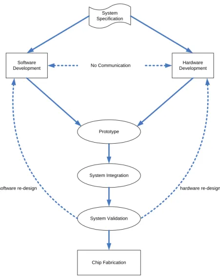
Frank Ghenassia in his book [Ghe05] states that the design flow is a rigorous engineering methodology or process for conceiving, verifying, validating, and delivering a final integrated circuit design to production, at a precisely controlled level of quality. Moreover, he gives also a look into the traditional design flow of an embedded system as shown in figure 2.1. This design flow starts with the design specification given by the client. Based on this specification two separate developments of the hardware and software begins independently. Note that the two developments take place totally independently without any regard of others’ existence. The two designs are kept separate until the prototype of the system-under-design is ready to be tested.
In a traditional design flow, the hardware design development usually begins with the creation of hardware models using hardware description languages (HDLs) like vhdl or Verilog. These models are then simulated for functional verification or correctness of the behavior of the module. Finally, synthesis is performed to obtain the code netlist. Later this design is laid on the chip to build our basic prototype. On the other hand, the software development goes independently without any knowledge about the hardware design. Although the software
2.2. SYSTEMS ON CHIP (SOCS) DESIGN FLOW 7 System Specification Software Development No Communication Hardware Development Chip Fabrication Prototype System Integration System Validation
software re-design hardware re-design
Figure 2.1: Traditional SoC Design Flow.
coding starts quite early in this way, but the testing of this code can only happen when the hardware design prototype is available.
One of the biggest disadvantages of the traditional design flow approach is the system validation at quite late stages of the design. Until the system prototype is ready and simulated along with the software design, we cannot validate the system. This problem is augmented with the fact that the software and hardware designs are modeled independently and without co-ordination. Hence, when at the later design stages a problem evolves, it costs more to correct it and re-design the system prototype. Moreover, the simulation speed for the designs at this level is very slow making the task of validating huge designs to be very long.
A new and classical system level design flow approach is shown in the figure 2.2. This classical design flow differs from the traditional system design flow in many ways. The tradi-tional design flow uses a single system specification to describe both hardware and software. On the other hand, classical design flow models use the Y-chart methodology [Erb06] for the
8 CHAPTER 2. ELECTRONIC SYSTEMS DESIGN hardware/software partitioning. This methodology uses a clear separation between an algo-rithmic/application model, an architecture model and an explicit mapping step to relate the algorithmic model to the architecture model. The application model describes the functional behavior of an application independent of architectural specification whereas the architecture model defines the system architecture characteristics. Thus, unlike the traditional approach in which hardware and software simulation are regarded as the co-operating parts, the Y-chart approach distinguishes algorithm/application and architecture simulation where the lat-ter involves simulation of programmable as well as reconfigurable/dedicated parts [Erb06]. Moreover, in the traditional design flow, the system validation is not possible until the design prototype is ready whereas in the present time classical modeling approaches, the system can be hardware/software simulated just after the initial design specification phase. This co-simulation [Sch03] is absolutely necessary for the software development such that the software design teams can have an idea of the underlying hardware resources to be utilized efficiently. In the traditional approach, the software development can only proceed when the hardware development phase has completed whereas in the current practice, hardware and software are partitioned to co-simulate at the same time. Partitioning is the process of choosing what al-gorithms (or parts thereof) defined in the specification to implement in software components running on processors, what to implement in hardware components, and the division of al-gorithms within the software and hardware components [BMP07]. There are limitations for this as the developed code depends on the underlying hardware used. For this purpose, tech-niques have been developed to enable the software to run on virtual hardware models or virtual platforms like the ones using transaction models (discussed in detail later). This approach dramatically reduces the Time-to-Market (TTM) duration due to reduced number of errors and early system validation. Time-to-Market is the time duration that it takes for a system chip design to be materialized and introduced to the market and is an important index to judge the performance of design techniques used.
2.2.2
Stages of SoC Design Flow
A classical system level design flow (shown in the figure 2.2) can be divided into three main phases: system specification phase, architecture exploration phase and the system implemen-tation phase, all discussed next.
System specification
In the system specification phase, we identify the requirements that the chip has to fulfill. SoC provides a variety of features on a single chip including interaction with the other component modules and with the user, which makes it quite complex. The SoC specification includes the desired requirements from the end-user and the specific constraints being enforced by the surrounding environment. These constraints can be of a vast variety. For instance, for a multimedia application, the loss of data is not as important as the jitters and the delay in the communication whereas for critical embedded applications like in avionics, the systems have to be real-time as well as accurate in data. All such constraints are taken into account while designing a chip.
Architecture exploration
System specification phase leads to the architecture exploration phase during which the system architect determines the hardware configuration that will be necessary to meet the needs
2.2. SYSTEMS ON CHIP (SOCS) DESIGN FLOW 9 System Implementation Architecture Exploration System Specification hardware re-design Specification Functional Validation co-design Algorithmic Models System Analysis Architectural Models Architectural Validation Component Database Hardware Implementation Memory map Processor & peripherals Application specific co-processor Software Implementation Device driver RTOS User software Hw/Sw Co-simulation Co-verification Chip Fabrication
Figure 2.2: Classical System Level Design Flow.
expressed before. This step is broken down into two parts: functional modeling phase and system analysis phase.
10 CHAPTER 2. ELECTRONIC SYSTEMS DESIGN the software of the system are designed. Usually hardware modeling deals with the resource allocation while software modeling includes the definition of key functions, programs and rou-tines. These models identify the key building blocks of the system and their interconnections. They provide the possibility of an early functional and architectural validation of the system, co-designing hardware and software models. These models also give us a big picture about the requirements and interdependence of system modules leading to early detection of logical system errors. The algorithmic and architectural models used for the creation of functional model are rarely rebuilt from scratch in each new chip but are usually reused from an IP library. Here, a standard like ip-xact [SPI08], which is at the heart of this thesis, plays a key role by providing component IP databases. In fact the blocks which constitute a system on chip are generally created to be reused and usually a new system design architecture reuses and integrates these components, leading us to the concept of platform based systems [SVCDBS04]. System analysis phase decides the low level details about the system design. This step crucially determines the remaining design flow as by this time the system architect must determine how the chip will be incorporated to meet the requirements specified in the previous phase. A key parameter for this determination is the hardware/software partitioning. At the end of this phase we obtain a hardware/software partitioned system that has an adequately allocated proportion of design functionality between the hardware and the software. After this phase our system architecture is finalized and we can proceed with the system implementation phase. As an example we consider a functional model of a system running some specific programs. There are several ways to execute this specific program on the given model. In one approach, we can assign the task to a processor and hence algorithm is implemented in the software. This approach is quite easy and offers great flexibility as we can alter the program (to a limit) even after the hardware fabrication. However, if the executed program is too complex, the processors are not an efficient choice in terms of time and power consumption. This leads us to the second approach of creating asics (Application Specific Integrated Circuits) which costs us the flexibility to modify but are very efficient in terms of energy and time consumption leading to shorter time-to-market durations. A third approach placed in between these two is of the use of fpgas. fpgas are fully customizable hardware units and give more flexibility for hardware design as compared to asics. The system analysis process finally leads us to the determination of a system whose software has been specified as well as components that will execute it. This gives way to the development of respective software or hardware implementations in the next phase.
System implementation
Following the system analysis, we have the system implementation phase after which we have the software and hardware implementation models of the system.
In the present times, the software implementation for a SoC design has become a pivotal part for the overall system development. Software development includes variety of program-ming including the low level device drivers coding, the operating system development and management, and finally the problem specific end-user application. With the current trends of evolution of system-on-chip architectures, having generalized multiprocessor system designs, the importance of implementation software augments. The device drivers and operating sys-tems are the softwares that are directly dependent on the underlying hardware and make the application programming simple and hardware independent. Software programming heavily depends on the system requirements specification. On one side a simple SoC design can have a naive software implementation whereas on the other side if the software is implemented for the critical embedded applications like in avionics or life saving devices, its correctness and proper functioning matters a lot. Various design techniques have emerged in the eda industry
2.2. SYSTEMS ON CHIP (SOCS) DESIGN FLOW 11 to deal with the verification and validation of such software implementations.
Transaction Level Modeling (TLM)
Communicating Processes Untimed Functional Model TLM Programmers’ View
CP UTF TLM-PV
Communicating Processes with Time Timed Functional Model TLM Programmers’ View with Time
CPT TF TLM-PVT
Bus Cycle Accurate Cycle Approximate Cycle Callable BCA CA CC Cycle Accurate Cycle Callable CA CC
Register Transfer Level Model RTL
System Architectural (Algorithmic) Model SAM
- No notion of time - Transactions - Functional verification - Algorithm validation - Notion of time - Transactions - Application Sw development - Architectural analysis - Cycle accurate - Signal accurate - Driver development - Micro architectural analysis Higher simulation speed Increasing design complexity
Figure 2.3: ESL System Design Layers.
The hardware implementation is the process of creating models that may be synthesized into gate-level models. These models of a system design can be represented at different mod-eling levels. Every design engineer can have his own view of the abstraction level of system design. There can be potentially hundreds of abstraction levels for an electronic system design, but mainly we focus on three commonly used abstraction levels [Rev08] namely System Archi-tectural Model (SAM), Transactional Level Modeling (tlm), and Register Transfer Level (rtl) (as shown in figure2.3). From a system designer’s view point, the design starts from a model specification. System Architectural Model comprises of design specification and its algorithmic model. The design specification is the system requirement usually documented in a textual language. Then this requirement specification is converted into a simple model comprising of functions. Both these representations give the broad picture of the system representation and are usually not meant for simulation purposes. These representations are characterized by untimed transactions and can be used for high level system validation purposes. At the higher levels of abstraction, the range of modeling levels is coarsely defined and overlaps with the adjacent levels. Transaction Level Modeling (tlm) is an abstract modeling level providing the initial executable model of the system, hence leading to early system simulation and validation. While most of these levels are optional and are only there to facilitate the design flow, the last rtl model is mandatory. rtl models give the most precise way to represent the components present on the chip, and which can be automatically synthesized into a logical combination of elementary operations (logic gates) whose implementation is materialized through the transis-tors and integrated circuits (ICs) engraved on the circuit chips. These different modeling levels demand different models and languages. We present three families of languages addressing the
12 CHAPTER 2. ELECTRONIC SYSTEMS DESIGN various levels.
2.3
Synchronous Languages
Most electronic systems are reactive and present to some extent real-time features. Syn-chronous languages have been developed to deal with reactive systems. We present them in this chapter on electronic systems for three main reasons:
the importance of electronic systems in real-time and embedded applications;
the intrinsic interest of the synchronous paradigm and its relationship with synchronous circuits;
the recent evolution of some synchronous languages, like Esterel, to electronic system design.
2.3.1
Reactive and real-time systems
Reactive systems interact with the real-world environment by reading the sensors or receiving interrupts and produce the output commands/information. For correct functionality they have to produce valid data under strict time constraints (deadlines) hence leading to both logical and temporal correctness of real-time systems [BB91]. Safety is a critical issue for many real-time systems with numerous human lives at stake. The behavior programming in general and especially of such systems can be done using combination of finite state machines (fsms). StateCharts [Har87], which are hierarchical and concurrent state-transition models, can be used instead of a collection of fsms. Both fsms and StateCharts are normally implemented in hdls or C language. Such low-level languages do not help much to deal with the complexity of the systems and have limited component reuse, difficult to debug, and error-prone (with error detection at late design stages). Moreover, these languages are not adequate for high level design for which system-level design languages like SystemC [IEE05] and SpecC [DGG02] were introduced lately. These system-level languages facilitated the hardware/software co-design and co-simulation leading to early system validation. However they lack a formal semantics and hence are not a good choice for the formal verification and the correct-by-construction [Ber07] implementation of systems.
Computer systems broadly fall into three categories based on their behavior; transforma-tional systems, interactive systems, and reactive/reflex systems [Hal92, chapter 1]. Example of transformational systems is the compiler which takes input code and generates an output targeted for a specific architecture. The interactive systems are the ones which intake several input stimuli and produce various output signals according to the input signals, without any regard for the time taken to process this information. This means that the environment/client does not know when the output will be available. On the other side, the reactive systems are the ones in which correct functioning of the system not only depends on processing the input but also on the timely response of the system (just like our reflexes). Hence the interactive systems are non-deterministic while the reactive systems are predictable. In another way, we can say that the interactive systems have got their own pace of execution while interacting with the environment whereas the reactive systems theoretically react instantly to the inputs and their pace of execution is dictated by the environment. All these types of computer systems are shown graphically in the figure2.4.
The behavior of a reactive system is usually described as a sequence of reactions, resulting from execution cycles in which (sequentially) it reads inputs from the sensors, processes that
2.3. SYNCHRONOUS LANGUAGES 13 Input data (from sensors) Output data (to actuators) Execution Cycle Control Input Compiler Input Output
Stimuli Computation Effects
Control Output
(a) Transformational Systems (b) Interactive Systems
(c) Reactive Systems
Figure 2.4: Types of Computer Systems.
input data based on the control commands, and finally generates output to manipulate the actuators. The reactive systems are generally implemented by finite state machines (fsms). Traditionally, the tools to design reactive systems forced the users to choose between the de-terminism and concurrency for a system. Contrary to the traditional programming languages, synchronous languages prove to be the good candidate for the programming of reactive/real-time systems. These languages provided the system designers with the ideal primitives to deal with the issues related to reactive systems design. Synchronous Languages were initially introduced in the beginning of 1980s 1. They are based on the perfect synchrony hypothe-sis [Ber00b], in which concurrent processes are able to perform computation and exchange information in zero time. Such a synchronous model has a great appeal in the real-time mod-eling domain including embedded systems (avionics, SoC design), communication systems and hardware design. These languages can be classified as declarative languages and imperative languages, based on their programming style. Declarative synchronous languages adopt a data-flow style. They express the logic of a computation without explicitly describing its control flow. They focus on ‘what’ the program should accomplish. Synchronous programming lan-guages like Lustre [HCRP91] and Signal [LGLBLM91] represent this category. The former is a synchronous flow language that relies on equations; the latter is more general and considers relations. Both can be efficiently used for steady-process control and signal processing applica-tions. In the contrast, imperative synchronous languages describe (reactive) behavior in terms of statements that change a program state; they focus on the ‘how’. Esterel [BdS91,Ber00b] and SyncCharts [And96] represent such languages. They are better used in control-intensive
14 CHAPTER 2. ELECTRONIC SYSTEMS DESIGN applications. Recently, developments in the synchronous language tools have made this classi-fication a bit vague. For instance SCADE, a Lustre-based industrial synchronous methodology and tool-set2, has integrated ssms (Safe State Machines, a variant of SyncCharts) which are control-oriented, and Esterel (version 7) now supports Lustre-like equations.
The synchronous languages provide the formal semantics as well as the abstract represen-tation of designs at system level which makes them a good choice for behavior represenrepresen-tation. The imperative programming languages like Esterel also facilitate the designing of fsms, dis-cussed in the next subsection.
2.3.2
Esterel Language
In our work, to program the reactive applications and fsms, we have used Esterel Language along with SyncCharts. These applications can be represented using textual (Esterel) as well as graphical (SyncCharts) forms. SyncCharts is a graphical language expressing hierarchical and concurrent state machines. SyncCharts is a model akin to StateCharts. However, they differ on their semantics: SyncCharts adheres to the perfect synchrony hypothesis while State-Charts has many synchronous but not perfect synchronous semantics [vdB94,HN96]. Because SyncCharts and Esterel share a common semantics, they can be freely mixed in a specifica-tion. In the Esterel Studio Suite, a syncChart is first translated into a semantically equivalent Esterel program, and then treated as an ordinary Esterel program. In the following, an Esterel program stands for its textual as well its graphical format. The compilation chain of Esterel can generate program codes in languages like C, vhdl, or SystemC. These programs have a behavior equivalent to the one specified by the Esterel program, but concurrency has been compiled out.
The early versions of the Esterel language [BdS91] (in the 80’s and 90’s) targeted reactive systems and safety-critical systems without special consideration for electronic systems. Since 1999, within an industrial context, the Esterel compiler has undergone broad syntactic exten-sions, leading to Esterel v7 [Est05], and its main application domain has become electronic system design. To understand this evolution we have to briefly describe the basics of Esterel and bring out the main changes in the language.
Esterel v5
The syntax and an informal semantics of Esterel v5 are presented in a language primer [Ber00a]. A book [PBEB07] describes formal semantics of the language and different compilers. An Esterel program can be seen as specifying a collection of communicating threads running concurrently. Here, concurrency should be understood as cooperation, not competition as it is often the case in interactive systems. Note that most of the Esterel compilers generate a sequential executable code; thus the threads we consider are logical or conceptual, not physical (run-time threads).
The simplest way to understand the behavior of a synchronous program is to consider that each thread performs a cycle-based computation in which environment actions strictly alternates with thread actions. The many threads that constitute the program communicate and interact during their active phase. These concurrent/cooperative evolutions define an instant. All the actions and the information exchanges are simultaneous (i.e.,at the same instant).
In Esterel, signals are the only means of communication and provide the unique support for communication between threads. When a thread emits a signal, this signal is instantly broadcast and thus can be seen by any thread that may be concerned. A signal is either
2.3. SYNCHRONOUS LANGUAGES 15 present or absent at a given instant. Pure signals carry only this presence information. Valued signals also convey a typed value.
To emit or test a signal is a reactive statement in Esterel. Preemptions are other typical reactive statements. Preemption is the capability for a thread to block the execution of another thread. The preemption can be temporary (suspension) or definitive (abortion). The simplest form of abortion is theawaitstatement which makes a thread wait for the next presence of a signal.
Syntactically, an Esterel program consists of one or several modules. A module is a program unit that has a declarative part (header ) and an imperative part (body). The header specifies the interface of the module: it declares signals with their direction (input, output, inputoutput) and their type. The body contains executable statements and structured blocks of statements that can be nested and composed in parallel or in sequence. Modules can also be instantiated in a module, allowing hierarchical specifications. Local signals declared within the body of a module serve as communication medium for its concurrent threads.
The semantics of Esterel guarantees that preemptions at any depth and any degree of con-currency are always deterministic. The unicity of each signal status (presence and value, if any) is also assured at each instant. This makes Esterel an outstanding language for programming complex control-dominated systems that require fully predictable behavior.
Note that Esterel, like the other synchronous languages [Hal92], relies on a logical time rather than physical time. Only the ordering of event occurrences is meaningful, not the “physical” duration between them. An event can occur before or after another one, but it is also possible for them to occur simultaneously. In contrast to non-synchronous models, the notion of simultaneity is precisely defined in synchronous languages and characterizes things occurring at the same instant.
The compilation of an Esterel program is a hard task [Ber00b,PBEB07]. Each signal must respect two coherence rules:
1. a signal is only present or absent in an instant, never both;
2. during a reaction, for any output or local signal, all the emit actions must precede any test action.
The latter rule is a form of causality relationship not easy to check on complex programs. The constructive semantics has defined simple correctness criteria for causality. A second difficulty came from the size of the generated code when fsms were taken as target representation. In the mid 90’s appeared the circuit semantics of Esterel. This semantics translates Esterel programs into sequential circuits, or equivalently into logical equations, similar to the ones found in Lustre programs. This logical representation is amenable to powerful optimizations that have been extensively studied in the hardware community. Direct implementations in hardware and software can be generated from the optimized circuits. The close relationship between the Esterel semantics and the circuits is probably one of the main reasons why Esterel has successfully evolved to Esterel v7 which is equipped to address electronic design.
Esterel v7
Esterel v5 failed at modeling/programming large-scale system-level or hardware designs. It lacked prominent features [BKS03] in its ability to describe data paths, to deal with bit-vectors, to directly support Moore machines, etc. Esterel v7 has corrected these deficiencies by syntactic improvements that have left the semantics of the language mostly unchanged.
For our usage of Esterel in this thesis, the most interesting changes are in the declarative part. Three types of program units are now available:
16 CHAPTER 2. ELECTRONIC SYSTEMS DESIGN Data unit which declares data types, constants, functions, or procedures. It can extend
one or several other data units by importing all the objects they declare.
Interface unit which primarily declares input/output signals and can also extend other data and interface units by importing all their data and signal declarations. Interface units can also be declared as mirror of some other interface which means that the inter-face type is the same, but the interinter-face signal directions are reversed.
Module unit that defines the reactive behavior of the system. The header of the module can extend data and interface units by importing the objects they declare.
Units can be generic, which allows better reuse. Also of interest is the introduction of port. A port is a group of signals typed by an interface. A port allows renaming of signals in interface instantiations. Esterel v7 supports arrays. Ports and signals can be declared as arrays. The array mechanism facilitates the specification and the handling of large structures like buses in computer architecture.
Modern hardware designs usually have more than one clock. Moreover, for power saving, these clocks can be turned on and off. To address these new design challenges, Esterel v7 supports multi-clocking and adopts the GALS (Globally Asynchronous Locally Synchronous) design paradigm. A new kind of signal (clock) and a new kind of unit (multi-clock) have been added to the language. A multi-clock unit is similar to a module unit but it declares one or many clocks in its header. It can also define local signals and clocks. Several module and multi-clock units can be instantiated in a multi-clock unit. The classic module instances perform computations, usually driven by an explicit clock, while the enclosing multi-clock unit only deals with clocks and signals.
All the correct Esterel programs are synthesizable in hardware and software, including multi-clock designs. Moreover, the programming structure of Esterel v7 resembles more to the hdls. So, the advent of Esterel v7 has greatly improved the capabilities of the language for use in eda (Electronic Design Automation) applications. Besides all these language improvements, Esterel Studio now supports architecture diagrams, a graphical notation similar to hardware block-diagrams and representing the Esterel design structure.
2.4
Transactional Level Modeling
Transaction Level Modeling (tlm) is a high level approach to modeling digital systems where details of communication among modules are separated from the details of the implementation of the functional units or of the communication architecture [Gro02]. Low simulation speeds and complex SoC designs turn the system designers towards the more abstract level system representations. Transaction Level Modeling (tlm) is one such abstract system representa-tion which can be regarded as the first representarepresenta-tion of the implemented components after hardware/software partitioning. Because of its high level of abstraction, tlm gives us high simulation speeds for a complete system on chip design representation as compared to respec-tive rtl models. Figure 2.3shows the tlm abstraction layer. The transactional level itself is
not a particularly defined modeling level but is a collective logical name for four model layers communicating processes (cp), communicating processes with time (cpt), bus cycle accurate (bca), and cycle accurate (ca).
The communicating processes (cp) models are also called as untimed functional models (utf). They are the architectural models targeted at early functional modeling and verifi-cation of systems where timing annotations are not required. They consist of asynchronous concurrent message-passing elements as there is no notion of time at this level just as for
2.5. REGISTER TRANSFER LEVEL 17 system architectural models. As they do not contain unnecessary implementation details, they can be developed, optimized and rapidly modified to the designers’ needs. These models are characterized by high simulation speeds and less complex design models. On the other hand, the communicating processes with time (cpt) model is a micro-architectural model con-taining essential time annotations for behavioral and communication specifications [Ghe05]. Compared to cp models, these cpt models are closer to rtl models. These models focus on the simulation accuracy, architecture analysis and real-time software development. The Open SystemC Initiative (OSCI) 3 has defined the above given modeling levels from the software
engineering point of view. cp level is also called as the programmers’ view (pv) and cpt level is called as programmers’ view with time (pvt).
The bus cycle accurate (BCA) models consider the temporal granularity at the bus trans-action levels. The message passing is usually atomic. At bus cycle accurate levels also known as cycle-approximate levels, the actual operations of the bus or ip accesses are present, but the timing between them is not known precisely. In cycle accurate models, the communication information is passed at clock boundaries and exact cycle counts are known. Gate propagation level is the most detailed hardware implementation model at which the timing within the clock period is also known precisely.
Electronic System Level being an established approach for System-on-a-chip (SoC) design can be accomplished through the use of SystemC as an abstract modeling language. SystemC language was developed by OSCI, a not-for-profit organization [SystemC], in 1999. It is a actually a collection library of C++ routines, macros and classes that can be compiled with any conventional C++ compiler. Its working and capabilities are similar to hdls (vhdl and Verilog) like the simulation of concurrent processes, events, and signals but provides more flexibility, greater expressiveness, different templates, and data types, as well as the full power of the C++ language. It can be considered as a language for high level structure modeling and behavior representation using constructs like communication channels, buses, interfaces, modules and threads. Due to these features, SystemC is often duly associated with esl design and tlm. It has got a wide variety of application like software development, system-level modeling, architectural exploration, functional verification, high-level synthesis, and performance modeling.
Modules are the basic building blocks of a SystemC design structure. A SystemC model usually consists of several modules that communicate through ports. Modules are represented using two types of C++ functions, methods and threads. Threads are the function calls that can be paused using the wait statement whereas methods run till the end of their execution once triggered or called. SystemC models execute in discrete events of time. Channels are the main communication of SystemC connecting module interfaces. They can be either simple wires or complex communication mechanisms like FIFOs. Modules, ports, interfaces, and Channels together form interface-based design style, where computation and communication can be modeled separately. SystemC also introduces a number of different data types.
2.5
Register Transfer Level
Register transfer level (rtl) refers to that level of abstraction at which a circuit is described as synchronous transfers between functional units, such as multipliers and arithmetic-logic units, and register files [Gro02]. The basic building blocks of an rtl design are modules constructed from simple gates. These building blocks are comprised of functional units, such as adders and comparators, storage components, such as registers, and data routing components, such as multiplexers. This abstraction level is also referred to as module-level abstraction [Chu06].
18 CHAPTER 2. ELECTRONIC SYSTEMS DESIGN Contrary to the gate level representation, rt level data representation is more abstract. Ports and data types are used to represent groups of hardware connections and signals respectively. Similarly, the behavioral description of a system, to specify the functional operations at this level, generally uses finite state machines (fsms) to express the data flow. The system state of the fsm describes the internal behavior state of the system at any specific instance of time. The timing representation at the rt level is shown by a clock signal input to the storage components like register blocks. These clock signals act as a trigger for the actions in the synchronous modules. Data is manipulated (latched, sampled, read, written etc.) on the edge (rising or falling) of these clock signals. In this way, these clocks act as the synchronizing pulse for the system. The clock pulses have frequency limitations by the hardware implementation. Clock signals have to be of long enough durations that they account for the system propagation delays. Thus due to the use of clocks, we do not usually consider the system changes occurring within the clock cycle and the system timing is considered in terms of number of clock cycles. A digital system design can be described at different levels of abstraction and with variety of view points, depending on the background and knowledge of the designer and requirements of the system. Here comes the role of the hardware description languages (hdls) which let the designers to accurately model the designs from the structural and behavioral view points, at a desired level of abstraction. This thing gives the system designers an opportunity to focus their efforts on the design and do not mix up the different view points of a design also. This effort also gives a standardized approach to the system design and make various designs compatible with each other. Traditional programming languages are not adequate for modeling digital hardware which also increases the necessity of the role of hardware description languages. The traditional general purpose languages like C follow the sequential process paradigm which helps the programmers to easily formulate a step by step design approach. On the other hand the digital hardware consists of concurrently operating small modules of sequential or combinational circuits. Such sort of design modeling is not possible with general purpose languages.
One of the popular hardware description language that we focus on in our work is vhdl. vhdl stands for vhsic (Very High Speed Integrated Circuit) hdl. It is used to describe the structure and behavior of a system. It can describe a system at various levels like behavior, data flow, and structure. vhdl system design and programming is usually a top-down de-sign methodology where a system dede-sign is modeled at a higher level. Later this model is tested using simulation techniques and then refined to low level synthesizable hardware im-plementations. A typical vhdl module consists of two major parts: an entity declaration and an architecture description. The entity declaration defines the interface of the module. This interface is visible and available to the other components. The architecture body spec-ifies the internal operation or organization of the circuit. vhdl supports “hardware” types (bit, bit vector,. . . ), and multi-valued logic types (sd logic) through its ieee library. The statements inside the architecture body are executed as concurrent building blocks (in paral-lel). An after keyword is used to trigger the statement blocks at a particular instance of time relative to the input clock. These vhdl modules (also known as components) once declared and defined, can be instantiated in the architecture body of other modules. Hence, we can have a library of defined components which can be used in our designs as needed. Common vhdl editors/simulators come with a set of such libraries having commonly used digital design components. When instantiating a component in our design, the port map keyword is used to bind the interfaces of the instantiated component to the ports of the component specifica-tion. Such a structural description of our design facilitates the hierarchical design of complex systems. vhdl also facilitates us to program sequential statements. Such a code is sometimes also referred to as behavioral description. These features are considered as an exception to the vhdl semantics [Chu06]. These statements are encapsulated in a special construct known as