HAL Id: hal-02492987
https://hal.archives-ouvertes.fr/hal-02492987
Submitted on 27 Feb 2020HAL is a multi-disciplinary open access archive for the deposit and dissemination of sci-entific research documents, whether they are pub-lished or not. The documents may come from teaching and research institutions in France or abroad, or from public or private research centers.
L’archive ouverte pluridisciplinaire HAL, est destinée au dépôt et à la diffusion de documents scientifiques de niveau recherche, publiés ou non, émanant des établissements d’enseignement et de recherche français ou étrangers, des laboratoires publics ou privés.
High efficiency mesoscopic solar cells using CsPbI3
perovskite quantum dots enabled by chemical interface
engineering
Keqiang Chen, Wei Jin, Yupeng Zhang, Tingqiang Yang, Peter Reiss, Qiaohui
Zhong, Udo Bach, Qitao Li, Yingwei Wang, Han Zhang, et al.
To cite this version:
Keqiang Chen, Wei Jin, Yupeng Zhang, Tingqiang Yang, Peter Reiss, et al.. High efficiency mesoscopic solar cells using CsPbI3 perovskite quantum dots enabled by chemical interface engineering. Journal of the American Chemical Society, American Chemical Society, 2020, 142, pp.3775-3783. �hal-02492987�
High efficiency mesoscopic solar cells using CsPbI
3perovskite
quantum dots enabled by chemical interface engineering
Keqiang Chen1,2, Wei Jin1, Yupeng Zhang2, Tingqiang Yang1, Peter Reiss3,*, Qiaohui Zhong1, Udo Bach4, Qitao Li1, Yingwei Wang2, Han Zhang2, Qiaoliang Bao5,*, Yueli Liu1,*
1 State Key Laboratory of Silicate Materials for Architectures, School of Materials Science and
Engineering, Wuhan University of Technology, Wuhan, 430070, P. R. China
2 Institute of Microscale Optoelectronics, Collaborative Innovation Centre for Optoelectronic
Science & Technology, Key Laboratory of Optoelectronic Devices and Systems of Ministry of Education and Guangdong Province, College of Physics and Optoelectronic Engineering, Shenzhen Key Laboratory of Micro-Nano Photonic Information Technology, Guangdong Laboratory of Artificial Intelligence and Digital Economy (SZ), Shenzhen University, Shenzhen 518060, P.R. China
3 Univ. Grenoble-Alpes, CEA, CNRS, IRIG/SyMMES, STEP, 38000 Grenoble, France
4 Department of Chemical Engineering and ARC Centre of Excellence in Exciton Science,
Monash University, Clayton, Victoria 3800, Australia
5 Department of Materials Science and Engineering and ARC Centre of Excellence in Future
Low-Energy Electronics Technologies (FLEET), Monash University, Clayton, Victoria 3800, Australia
Corresponding authors:
[*] Prof. Yueli Liu Tel.: +86-27-87760159 E-mail: [email protected] (Yueli LIU)
Prof. Qiaoliang Bao Tel: +61 3 9905 4927 Email: [email protected] (Qiaoliang BAO) Dr. Peter Reiss Tel: +33 4 3878 9719 Email: [email protected] (Peter REISS)
Abstract
All-inorganic α-CsPbI3 perovskite quantum dots (QDs) are attracting high interest as solar
cell absorbers due to their appealing light harvesting properties and enhanced stability due to
the absence of volatile organic constituents. Moreover, ex situ synthesized QDs significantly
reduce the variability of the perovskite layer deposition process. However, it is highly
challenging to incorporate α-CsPbI3 QDs into mesoporous TiO2 (m-TiO2), which constitutes
the best performing electron transport material in state-of-the-art perovskite solar cells. Herein,
the m-TiO2 surface is engineered using an electron-rich cesium-ion containing methyl acetate
solution. As one effect of this treatment, the solid-liquid interfacial tension at the TiO2 surface
is reduced and the wettability is improved, facilitating the migration of the QDs into m-TiO2.
As a second effect Cs+ ions passivate the QD surface and promote the charge transfer at the
m-TiO2/QD interface, leading to an enhancement of the electron injection rate by a factor of three.
In combination with an ethanol-environment smoothing route significantly reducing the surface
roughness of the m-TiO2/QD layer, optimized devices exhibit highly reproducible power
conversion efficiencies exceeding 13%. The best cell with an efficiency of 14.32% (reverse
scan) reaches a short-circuit current density of 17.77 mA cm−2, which is an outstanding value
for QD-based perovskite solar cells.
Keywords: α-CsPbI3 quantum dots; all-inorganic perovskite solar cells; carrier separation and
Introduction
Colloidal quantum dots (QDs) have received tremendous attention owing to their
size-dependent optical, electronic, and surface chemistry properties, which offer exciting additional
possibilities with respect to bulk materials.1-4 These unique features promote their widespread
applications in optoelectronic devices. QD-based solar cells are regarded as a representative
candidate for obtaining power conversion efficiencies (PCEs) beyond the Shockley-Queisser
limit due to their high potential for multiple exciton generation.5-9 Moreover, the ex situ
preparation of the active material bears undeniable advantages in terms of device fabrication
and reproducibility over the in situ formation and crystallization of thin films during the
deposition process. This is particularly true in the case of lead halide perovskite solar cells, as
the formation of the perovskite thin film during the spin-coating process is extremely sensitive
to even subtle changes in the experimental conditions.
Cubic α-CsPbI3, an all-inorganic lead halide perovskite with comparable optoelectronic
properties but strongly enhanced stability, is considered to be a very appealing alternative to
organic-inorganic hybrid perovskites and a promising light-harvesting material for use in solar
cells.10-17 Importantly, in form of colloidal QDs the structure could effectively retain the black
cubic phase of CsPbI3 (direct band gap of 1.73 eV), which otherwise easily transforms to the
thermodynamically stable orthorhombic δ-CsPbI3 phase (indirect band gap of 2.82 eV) in thin
film structure.10, 18 Subsequently, the successful application of this material in planar perovskite
solar cells (PSCs) has been demonstrated, reaching very recently PCEs of up to 14.1%, which
constitutes the record value reported for QD-based solar cells.12, 19-22
To achieve high performances, both the optimization of the photoactive material (the
perovskite layer) and of the different interfaces (such as the electron transport material
(ETM)/perovskite interface, hole transport material (HTM)/perovskite interface) are important.
However, the reported CsPbI3 QD-based PSCs are focusing on the surface passivation of CsPbI3
been largely overlooked. By consequence, low short-circuit current densities (JSC, <15 mA
cm−2) as compared to hybrid perovskite thin film solar cells have been obtained, restricting the
performance of CsPbI3 QD-based PSCs. It is generally assumed that inefficient carrier
separation and transport are the principal reasons that limit JSC. Especially, extracting electrons
is less efficient than extracting holes from perovskites.23-25 Therefore, the optimization of the
ETM/QDs interface is of paramount importance to promote the electron transfer from the
perovskite to the ETM and enhance the JSC. So far, the use of mesoscopic TiO2 (m-TiO2) as an
ETM has led to the best performing thin-film PSCs due to the very large developed contact
interface with the perovskite, which is conducive to facilitate the carrier separation and
transport.26-29 This is confirmed by recent studies showing that the electron injectionefficiency
from CsPbI3 QDs into m-TiO2 can reach 99% with an injection rate of up to 2.1×10¹⁰ s-1.30
However, all-inorganic lead halide QD-based solar cells generally use compact TiO2 (c-TiO2)
rather than m-TiO2 as an ETM as it turns out to be highly challenging to homogeneously
incorporate QDs into the mesoporous structure during the short time of the film formation
process.12, 19, 31-32 Moreover, the surface roughness of m-TiO
2 films is usually much larger than
that of c-TiO2 films, which leads to the formation of a QD capping layer with irregular structure
that negatively impacts the TiO2/QD interface properties. Therefore, engineering the ETM layer
and the ETM/QDs interface are the key requirements to enhance the carrier separation and
photovoltaic properties in α-CsPbI3 QD-based PSCs.
Herein, we demonstrate a novel approach using a solution of cesium acetate (CsOAc) in
methyl acetate (MeOAc) for the surface modification of m-TiO2, which is then applied as an
ETM in α-CsPbI3 QD-based PSCs. The Cs-treatment results in significantly improved interface
properties enabling effective QD incorporation into the mesoporous TiO2 structure. It is found
that the electron injection rate of the Cs-treated m-TiO2/QD interface is about two times higher
than that of a c-TiO2/QD interface and three times higher than that of an untreated m-TiO2/QD
PCE values. In combination with an ethanol-environment smoothing route to flatten the
m-TiO2/QDs capping layer at the interface with the HTM, the as-fabricated devices deliver
reproducibly efficiencies exceeding 13%, with the best PCE value reaching 14.32% (reverse
scan) combined with an unprecedented high JSC of of 17.77 mA cm−2.
Results and Discussion
CsPbI3 QDs with a diameter of ~9.1 nm were prepared using a synthesis process similar
to that reported by Protesescu et al. (Figure S1b);10 synthetic details are given in the
Experimental Section. We stress that the purification process is of crucial importance for
fabricating high quality QD films. A single washing cycle (methyl acetate/octane) leaves excess
ligands on the surface of the QDs, resulting in poor charge transfer and transport properties of
the QD film. Moreover, excess ligands might also contribute to the redispersion of existing QD
layers during their sequential deposition via spin-coating. Three washing cycles, in turn, lead
to an insufficient ligand density on the QD surface and poor colloidal stability. The surface
ligand density was calculated according to the TEM and nuclear magnetic resonance (NMR)
results, as shown in Figure S1. Therefore, two purifying cycles were used to optimize the
surface ligand density of the CsPbI3 QDs.33 Concerning the HTM, spiro-OMeTAD dissolved in
chlorobenzene (CBZ) (named as CBZ-spiro) is usually used in PSCs.34 However, CsPbI3 QDs
can be redispersed in CBZ due to their organic ligand capping, which may induce their
solubilization during the HTM deposition. Therefore, methyl acetate (MeOAc) was chosen for
the preparation of the spiro HTM35 (as shown in Figure S2, MeOAc-spiro was used as the HTM
in all the PSCs except for the device shown in Figure S2a).
Figures S2b and S3 show the J-V characteristics of the CsPbI3 QD-based PSCs using
c-TiO2 (~40 nm) and m-TiO2 (~200 nm) as the ETM, respectively. It is clear that the JSC and PCE
values of the c-TiO2-based PSCs (c-PSC, 14.44 mA·cm-2, 8.77%) are significantly higher than
carrier separation and transport in case of the planar structure. We hypothesize that the low
performance of the m-PSCs is related to the inefficient QD loading and poorly controlled
interface between the m-TiO2 ETM and CsPbI3 QDs. Figure S4 shows STEM-EDS elemental
mapping of the cross-section of the m-TiO2/CsPbI3 film. Unsurprisingly, Cs, Pb, and I were not
detected within the m-TiO2 layer, i.e., CsPbI3 could not incorporate efficiently into the
mesoporous TiO2 structure. As a result, all potential advantages of the mesoporous morphology
with respect to compact TiO2 are lost.
Chemical interface engineering is a potent way to improve the quality of the boundary
between the ETM and the perovskite layer as has been demonstrated in the case of
polycrystalline PSCs. There, mainly bifunctional molecules containing carboxylate groups for
binding to the TiO2 surface and amine/ammonium groups for hydrogen bonding with the iodine
ions of hybrid perovskites have been utilized, resulting in enhanced charge extraction and
eventually in improved morphology as well as stability.36-38 Here, a novel Cs-treatment
procedure is introduced to optimize the interface between m-TiO2 and CsPbI3 QDs. Briefly, a
saturatedMeOAc solution of CsOAc was spin-coated on the m-TiO2 film before depositing the
CsPbI3 QDs. Figure 1a shows the cross-sectional image of the FTO/Cs-m-TiO2/CsPbI3 film
visualized using high-resolution high-angle annular dark-field (HAADF) scanning transmission
electron microscopy (STEM). One can clearly identify the interface between the CsPbI3 QDs
(capping layer) and the mesoporous TiO2 film. Moreover, the outline of the TiO2 nanocrystals
forming the mesoporous structure and the voids between them disappeared when compared
with the pristine TiO2 film (cf. Fig. S4). The high-resolution TEM (HRTEM) image of area 1
in Figure 1a indicates that the TiO2 film is filled with CsPbI3 QDs (Figure 1b) and the Fourier
transformation pattern of the CsPbI3 QDs (Figure 1c) further confirms their crystalline
structure. The spots can be indexed as (001) and (002) crystal plane reflections from α-CsPbI3.
STEM-EDS mapping was used to determine the elemental distribution in the
untreated m-TiO2 (Figure S4, atom ratio of Cs:Pb:I:Ti:O is 1:1.10:2.94:4.32:11.27), Cs, Pb, and
I are present in significant amounts within the full depth of the TiO2 layer (atom ratio of
Cs:Pb:I:Ti:O is 1:1.04:2.85:3.11:9.42). Therefore, we can conclude that CsPbI3 QDs are
successfully incorporated into the mesoporous TiO2 structure after Cs-treatment.
Figure 1. (a) HAADF STEM cross-sectional image of a FTO/Cs-m-TiO2/CsPbI3 QDs film. (b)
HRTEM image from area 1 in (a) demonstrating the presence of CsPbI3 QDs within the
mesoporous structure. (c) Fourier transform image of the CsPbI3 QDs shown in (b). (d)
STEM-EDS elemental mapping from the cross-section of a Cs-m-TiO2/CsPbI3 film.
The different behavior of Cs-treated TiO2 is ascribed to the synergetic effect from MeOAc
and the surface modification induced by CsOAc. Firstly, as shown in control experiments
without CsOAc, MeOAc reduces the surface density of ligands on the QDs (Figure S5a and
contact angle measurements (Figures S5c and S5d) reveal that MeOAc also reduces the
solid-liquid interfacial tension, which improves the wettability of the TiO2 substrate with the
hydrophobic QD colloidal solution. To get further insight into this aspect, density functional
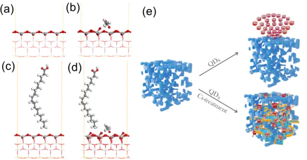
theory (DFT) calculations have been performed, as shown in Figure 2. Oxygen atoms on the
(001) surface in TiO2 are 2-fold coordinated and electron-deficient. They show a high tendency
to adsorb QDs with electron-rich ligands (OA and OLA). The introduction of electron-rich
MeOAc passivates the TiO2 (001) surface, thus breaking Ti-O bonds and inducing surface
reconstruction (Figures 2a and 2b). Moreover, the adsorption of OA or OLA will further
promote the breaking of Ti-O bonds, as shown in Figures 2c, 2d, and S6. As a result, the
adsorptionenergy (Eads) of OA on the surface of the TiO2 film decreases from 2.29 eV (2.36 eV
for OLA) to 1.02 eV (1.04 eV) after introducing the MeOAc solution. In other words, the
surface treatment makes it much easier for QDs to enter into the mesoporous TiO2 structure and
to migrate within it.
Figure 2. Side view of calculated TiO2 (001) surfaces before (a) and after (b) the exposure to
MeOAc, respectively. Chemical structures of OA on a TiO2 (001) surface without (c) and with
(d) MeOAc, respectively (atoms at free surface layers and adsorbed molecules are displayed as
ball-and-stick models, while the others are displayed as line models). (e) Schematic of QD/TiO2
Secondly, Cs+ ions that entered the mesoporous structure with the MeOAc solution can
improve the passivation of the QD surface and remove trap states from the QDs, which are
known to possess a PbI2-rich surface.10, 39 In addition, Cs+ ions can easily coordinate to the TiO2
surface. Therefore, we hypothesize that these ions also facilitate charge transfer from the QDs
to TiO2, which is indirectly demonstrated by comparing the J-V characteristics of PSCs
fabricated using MeOAc-modified m-TiO2 with spin-coating of the QDs, the traditional
immersion method (immersing the TiO2 photoanode into the QDs colloidal solution), and
CsOAc/MeOAc-treated m-TiO2 films with spin-coating (Figures S7 and 4b). Finally, annealing
at 100°C promotes the evaporation of excess MeOAc, which improves the cohesion between
TiO2 and QDs. In order to exclude possible influence of acetate, a saturatedMeOAc solution
of sodium acetate (NaOAc) was also employed to modify the m-TiO2 films. The J-V curve
shown in Figure S8 reveals that acetate has negligible influence on the PCE compared with
Figure S7, which further confirms the significance of Cs+ ions in the process. The scheme
shown in Figure 2e illustrates the incorporation of QD into the mesoporous layer induced by
the Cs-treatment: Without the Cs-treatment, CsPbI3 QDs can be easily adsorbed on the surface
of m-TiO2, which would block the TiO2 mesoporous framework. As a result, QDs will
accumulate on the surface of m-TiO2, and no QDs can migrate into the mesoporous layer. In
contrast, the introducing of CsOAc/MeOAc solution will reduce the adsorption energy of QDs
on the surface of TiO2 and facilitate the incorporation of QD into the mesoporous layer.
Moreover, the Cs+ ions induced by the Cs-treatment can further passivate the surface of QDs
and promote the charge transfer from the QDs to TiO2.
Steady-state photoluminescence (PL) spectra of CsPbI3 QDs dispersed in octane and of
various TiO2/CsPbI3 QD films are shown in Figure S9. A comparison of the solid-state samples
shows a marked decrease of the PL intensity when going from untreated m- or c-TiO2 to
Cs-treated m-TiO2. This indicates that the injection of photo-generated electrons from the QDs into
absorption (TA) spectroscopy was used to study the carrier kinetics within the TiO2/QD film.
Figure 3 shows the TA kinetics of the CsPbI3 QDs dispersed in octane and of various
TiO2/CsPbI3 QDs films, which were recorded 5 ps after band gap excitation at 692 nm. One
should note that the pump light intensity was fixed at ~1 µJ/cm2, in order to achieve results with
negligible influence of Auger recombination.30 The TA kinetics can be well fitted to a
single-exponential function ( ), where the time constants for the QDs,
m-TiO2/QDs, c-TiO2/QDs, and Cs-m-TiO2/QDs are found to be 462, 135, 91, and 51 ps,
respectively. The TA decay in the TiO2/QDs films is faster than in QDs colloidal solution, i.e.,
photo-induced electron-hole pairs in CsPbI3 QDs are separated by the films, and the electrons
are transferred to the TiO2 ETM. Furthermore, the electron injection rate constants
can be calculated using 40 and are found to be 0.52×10¹⁰ s−1,
0.88×10¹⁰ s−1, and 1.74×10¹⁰ s−1 for m-TiO2/QDs, c-TiO2/QDs, and Cs-m-TiO2/QDs films,
respectively. Summarizing, the electron injection rate in the Cs-m-TiO2/QDs film is
approximately a factor 2 higher than that in the c-TiO2/QDs film, and a factor 3 higher than that
in the m-TiO2/QDs film.
Figure 3. Schematic representation and TA kinetics of CsPbI3 QDs dispersed in octane and
0 0 exp( ) ) (t A t y y = - + t ) / (QDs TiO2
k
QDs TiO QDs TiO QDs k t t 1 1 ) ( ) / ( 2 2 = -+various TiO2/CsPbI3 QD films.
The obtained Cs-m-TiO2 films were employed as ETMs for the fabrication of CsPbI3
QD-based solar cells. A histogram of the PCE values obtained from 50 devices using Cs-m-TiO2
films is shown in Figure S10. One can see that even though some of the devices exhibit
comparably high performance (~13%), the reproducibility of the PSCs is not very good and
most cells are in the 11% range. Figure S11a shows a top-view SEM image of the m-TiO2 film.
It is clear that the mesoporous structure is irregular, and a significant undulance can be
observed. AFM measurements (Figure S11b) demonstrate that the film morphology is governed
by the macroscopic roughness of the m-TiO2 structure and QD treatment is only visible as a
finer texture on top of the TiO2 grains. The obtained value of surface roughness for the analyzed
film is as high as 48.8 nm, which leads inevitably to an irregular QD-coated m-TiO2 film
(surface roughness: 38.4 nm, Figure S11c). These are clearly not ideal conditions for the
subsequent deposition of the HTM layer and metal electrode and the high surface irregularity
can thus be considered as an important factor at the origin of the low reproducibility of the
PSCs. The high surface roughness of the pristine m-TiO2 film is related to the spin-coating
process used for its formation. We succeeded in flattening the m-TiO2 film considerably by
employing a post-deposition ethanol-environment smoothing procedure. Briefly, the freshly
prepared m-TiO2 films were kept for 3 min in a sealed box containing a few drops of ethanol at
room temperature and subsequently heated at open air for 7 min at 125 °C. The ethanol
atmosphere could reduce surface stress and relieve the surface irregularity of the m-TiO2
films.41 Figure S11d and S11e show SEM and AFM images of top-views of the smoothed
m-TiO2 films (s-m-TiO2). Their surfaces are much more homogeneous and flat than those of the
m-TiO2 films (Figure S11a and S11b), resulting in a surface roughness of the s-m-TiO2 film of
9.6 nm.As in the non-smoothed films, the planarity after QD deposition becomes even better,
with a surface roughness of 6.2 nm.
structure is shown in Figure 4a. Out of 50 devices all exhibited PCE values higher than 13%,
which suggests that the ethanol-environment smoothing process could greatly enhance the
performance of the PSCs (Figure S12). Importantly, the histograms of the solar cell
characteristics also show that the reproducibility of PSC device fabrication is strongly
improved. The characteristics of the best performing CsPbI3 QDs-based solar cell are displayed
in Figure 4b and 4c. It exhibited a PCE of 14.32% (reverse-scan), which represents one of the
highest performances for all-inorganic lead halide QD-based PSCs and for QD-based solar cells
in general. Notably, the JSC value reaches up to 17.77 mA cm−2, which is the highest reported
value for QD-based PSCs. Moreover, the device exhibits a stabilized power output (SPO,
measured at 0.84 V) of 13.87%. This device also exhibits maximum external quantum
efficiency (EQE) of ~92% (JInt = 17.09 mA cm−2), as shown in Figure 4c. The band gap of the
QD film calculated from the EQE spectrum is 1.75 eV, which is consistent with previous
reports.12 Finally, environmental stability studies showed that unencapsulated devices
maintained 90% of the initial PCE after being kept for 100 h under ambient conditions (cf.
Figure 4. (a) Schematic view of the CsPbI3 QD-based PSC with mesoporous structure. (b) J-V
curve, stable power output (measured at 0.84 V), and parameters of the champion device. (c)
EQE spectrum (red, left ordinate) and integrated current density (green, right ordinate) of the
device in panel (b).
A series of additional characterizations were performed to achieve a more detailed insight
into the physical effects induced by the Cs-treatment. First, the trap densities of TiO2/perovskite
layers with or without Cs-treatment were measured using the space-charge limited current
(SCLC) method.42-43 Electron-only devices with a structure of ITO/TiO2/CsPbI3
QDs/PCBM/Ag were fabricated, and the corresponding dark current-voltage characteristics are
shown in Figure 5a. The trap densities (Ntrap) were calculated according to the equation Ntrap =
2εrε0VTFL/eL2 where εr and ε0 are the relative dielectric constant and vacuum permittivity,
respectively, and e represents the elementary charge. The obtained values are 1.59×1015 cm−3
(with Cs-treatment) and 4.68×1015 cm−3 (without Cs-treatment) suggesting an effective
within the device was further characterized by investigating the light-intensity dependent J-V
properties, as shown in Figure 5b. A slope, expressed by nKT/q (where n, K, T, and q represent
the ideality factor, Boltzmann constant, absolute temperature, and elementary charge,
respectively) larger than 1 reveals the occurrence of trap-assisted recombination. Devices with
lower trap state density possess smaller slopes,20 which is the case for a typical Cs-treated
device (1.145 KT/q) in comparison with an untreated device (1.248 KT/q), further confirming
the reduction of trap-assisted recombination induced by the Cs-treatment. Third, the interfacial
charge transfer and recombination was also investigated, as shown in Figure 5c. The Nyquist
plots reveal that the Cs-treated device exhibits a smaller transfer resistance (Rtr, 15.99 Ω) and
larger recombination resistance (Rrec, 3139 Ω) than that of the untreated device (Rtr = 41.96 Ω,
Rrec = 2508 Ω), indicative of enhanced charge transfer and reduced charge recombination
processes in the Cs-treated device. Finally, time-resolved photoluminescence (TRPL) is applied
to further evaluate the charge transfer processes in the different devices. The carrier lifetime of
Cs-treated devices (1.37 ns, Table S1) is much shorter than that of untreated devices (3.79 ns),
which further suggests the more efficient charge transfer in the former. Therefore, we can
conclude that the Cs-treatment is an effective strategy to passivate trap states and enhance the
Figure 5. Device characteristics of the CsPbI3 QD films with or without Cs-treatment: (a)
space-charge limited current (SCLC) versus voltage; (b) light intensity versus open circuit
voltage; (c) Nyquist plots; (d) TRPL plots.
Conclusion
In summary, for the first time highly efficient CsPbI3 QD-based PSCs using mesoscopic
TiO2 as the ETM were demonstrated. Interface engineering with MeOAc/CsOAc not only
favors the incorporation of CsPbI3 QDs into the mesoporous TiO2 structure, but also results in
a well-defined contact between the m-TiO2 ETM and the QD layer, which greatly enhances
charge separation and electron injection rates. We have also shown that treatment with
MeOAc/MAI solution can lead to similar improvements as with MeOAc/CsOAc,
demonstrating the versatility of the approach. Additionally, an ethanol-environment smoothing
route was developed to drastically reduce the surface roughness of mesoscopic TiO2 films and
produce a planar CsPbI3 QD capping layer. The obtained devices exhibit PCE values exceeding
with a JSC of 17.77 mA cm−2, which is the highest value reported for QD-based PSCs and for
QD-based solar cells in general. The strategy of combining different approaches to engineer the
interface from the atomic to the nanometer scale can be generalized to improve the
performances not only of all-inorganic lead halide PSCs, but also of solar cells sensitized with
other types of QDs, in particular Pb-free perovskites, which are under intense current research.44
With a band gap of 1.75 eV, the CsPbI3 QD absorber is also ideally suited for integration into
Experimental Section
Preparation and isolation of CsPbI3 QDs:All chemicals were purchased from Aladdin
and used as received. 2 mmol of PbI2 (0.922 g, 99.9%) and 20 mL of 1-octadecene (ODE,
technical grade, 90%) were mixed in a three-neck flask and heated to 120°C in Ar. Thereafter,
2.5 mL of oleylamine (OLA, 80-90%) and 2.5 mL of oleic acid (OA, AR) were added to the
above solution. The mixture was held at this temperature for 30 min to dissolve PbI2 and remove
H2O and O2. Subsequently, 0.8 mL of a 0.5 M Cs-OA solution (5 mmol cesium acetate (CsOAc,
99.9% metals basis) dissolved in 10 mL OA at atmosphere) was swiftly injected into the
reaction mixture at 180°C. The reaction was ended by cooling down the mixture to room
temperature after 5 s. The CsPbI3 QDs were purified by adding 3 mL of methyl acetate (MeOAc,
anhydrous 99.5%) into 1 mL of the crude solution and centrifuging at 9000 rpm for 3 min. Then
1 mL of octane (>99%) was added to re-disperse the precipitate after the supernatant was
discarded. The QD-octane colloidal solution was centrifuged at 9000 rpm for 3 min a second
time to remove any insoluble aggregates. The above isolation process was repeated between
one and three times to yield CsPbI3 QDs with the desired surface ligand density (cf. Supporting
Information).
Device Fabrication: FTO substrates (12 Ω sq−1) were cleaned by sonicating in deionized
water and ethanol for 15 min, and the substrates were subsequently dried with compressed air
and treated with UV ozone. A compact-TiO2 (c-TiO2) blocking layer of 30 nm thickness was
deposited on the 1×2 cm2 cleaned FTO substrates from a 0.5 M TiCl
4 (99.9%) deionized water
solution at 70°C and annealed at 450°C for 60 min. Mesoporous TiO2 (m-TiO2) pastes were
prepared by following the procedure outlined in Ref. 29.35 An m-TiO2 layer of approximately
200 nm thickness was deposited by spin-coating at 3000 rpm for 20 s. An ethanol-environment
smoothing route was used to flatten the m-TiO2 film as follows: After spin-coating the m-TiO2
film was placed in a clean, sealed box with several drops of ethanol for 3 min at room
450°C heat treatment for 1h was used to sinter and to remove organics from the TiO2 films.
Two types of substrates with different morphologies (c-TiO2 or m-TiO2) were used for
Cs-treatment, which were named Cs-c-TiO2 or Cs-m-TiO2, respectively. 100 µL saturated
CsOAc/MeOAc solution was dropped on the TiO2-coated substrates for 10 s before spin-coating
at 2000 rpm for 10 s. Subsequently, QDs (~70 mg/mL in octane) were dropped onto these
substrates for 20s before spin-coating at 1000 rpm 10 s, followed by 2000 rpm 10 s. The QD
spin-coating process was repeated 2-4 times to yield a QD film with 200 nm thickness. A 5 min
heat treatment at 100°C was applied before spin-coating the HTM. The HTM was prepared by
spin-coating a saturated MeOAc/spiro-OMeTAD solution onto the film at 3000 rpm for 30 s.
All the spin-coating processes were performed under ambient conditions. Finally, Au electrodes
of ~80 nm thickness were deposited by evaporation.
Characterization: A focused ion beam (FIB) system (FEI 3D Quanta Nanolab FIB/SEM)
was used to fabricate the cross-sectional TEM lamellae. A Pt layer was pre-deposited in the
target area to avoid destroying the PSCs before FIB cross-section preparation. The
microstructures and chemical composition of the PSCs were examined with a transmission
electron microscope (TEM) equipped with an energy dispersive spectroscopy (EDS) detector
(FEI Tecnai G2 F20). SEM images were collected with a field emission scanning electron
microscope (FESEM, Hitachi S-4800). An atomic force microscope (AFM) with ScanAsyst in
air mode (Dimension Icon, Veeco Instruments/Bruker, Germany) was used to examine the
surface structure of the TiO2/QDs films. TA data were gathered with a Clark MXR-2010 laser
system. The J-Vdata was gathered with a Keithley 2400 SMU (Keithley Instruments, USA)
under excitation with a 300 W xenon lamp solar simulator (Newport 91160, USA). A calibrated
reference solar cell (Newport, USA) was used to confirm the intensity of the lamp (100 mW·cm
-2). A forward bias to reverse bias with a scan rate of 200 mV/s (step size and delay time were
set as 10 mV and 10 ms, respectively) was used to collect the J-V data. A metal aperture (0.09
constant voltage corresponding to the voltage at the maximum power point of the J-V curve
(0.82 V). The J-V curves were collected in ambient lab air. A Xenon lamp (150 W, Oriel)
equipped with a monochromator was used to collect the EQE spectra. A Nicolet Nexus-670
Fourier transform infrared (FTIR) spectrometer was used to gather FTIR spectra. The
fluorescence spectroscopy was excited with a 365 nm laser (RF-5301PC, Shimadzu, Japan).
TRPL spectroscopy was performed with a FLS 980 fluorescence spectrometer. EIS data were
collected using an Autolab PGSTAT320 N electrochemical workstation.
DFT Computation: The model was built based on the TiO2 (001) surface.45-47 Oxygen
atoms are supposed to be terminal atoms when the surface is annealed at 500 °C. The used QDs
are stabilized by OA and OLA binding with their carboxyl and amino groups to the surface,
respectively, while the alkyl chains are free to interact with the TiO2 (001) surface. To simplify
the interaction between m-TiO2 and the QDs, we calculated the adsorption capacity of OA and
OLA.
We performed periodic density functional calculations using the Dmol3 4.4 program.48-49
A Perdew-Burke-Ernzerhof (PBE) general gradient approximation (GGA) was used to describe
the exchange-correlation interactions.50 The double numeric quality basis set with polarization
functions (DNP) was used. The inner electrons on the Ti atoms were kept frozen and replaced
with an effective core potential (ECP), while other atoms in this study were treated with an
all-electron calculation. A supercell of the TiO2 (001) surface was 15.27×15.27×58.08 Å3, and
Brillouin-zone integrations were performed using a 2×2×1 Monkhorst-Pack grid. Fermi
smearing of 0.005 hartree was used to accelerate convergence, and the real space cutoff was set
to 5.3 Å in order to improve the computational performance. The energy, force, and
displacement convergence tolerance were 1 × 10⁻⁵ hartree, 2 × 10⁻³ hartree/Å, and 5 × 10⁻³ Å,
respectively. Several possible configurations of different adsorbates on TiO2 (001) were
considered for optimization, and all of the optimized atomic structures presented in this paper
Acknowledgements
This work is supported by the National Natural Science Foundation of China (No.
11674258, 51602305, 61875139, and 51702219), the 111 Project (No. B18038), Key projects
of Natural Science Foundation of Hubei Province (No. 2019CFA044), the Fundamental
Research Funds for the Central Universities (No. 2017II22GX), the Nature Science Foundation
of Guangdong Province (No. 2018A030313401), the Science and Technology Innovation
Commission of Shenzhen (No. JCYJ20170818141519879, JCYJ20170818141429525), Project
funded by China Postdoctoral Science Foundation (No. 2018M633102, 2017M620383),
Shenzhen Nanshan District Pilotage Team Program (LHTD20170006), and Australian
Research Council (ARC, FT150100450, IH150100006, DP160104575, CE170100026 and
CE170100039). We thank Centre for Materials Research and Analysis at Wuhan University of
Technology (WUT) for the assistance on sample measurements and Dr. Wei Wei (WUT) for
NMR measurements and analysis. P.R. acknowledges financial support from the French
Research Agency ANR (grants SuperSansPlomb 15-CE05-0023-01 and PERSIL
ANR-16-CE05-0019-02).
Competing interests
The authors declare no competing financial interests.
Supporting Information
TEM images of the CsPbI3 QDs, calculation of the surface ligand density, description of the
NMR measurements, J-V curves of control devices, STEM-EDS images of an untreated
m-TiO2/CsPbI3 film, FTIR and water contact angle measurements, AFM images and device
statistics.
References
1. Alivisatos, A. P., Semiconductor clusters, nanocrystals, and quantum dots. Science
1996, 271, 933-937.
2. Balazs, D. M.; Bijlsma, K. I.; Fang, H.-H.; Dirin, D. N.; Döbeli, M.; Kovalenko, M. V.; Loi, M. A., Stoichiometric control of the density of states in PbS colloidal quantum dot solids.
Sci. Adv. 2017, 3, eaao1558.
3. Boles, M. A.; Ling, D.; Hyeon, T.; Talapin, D. V., The surface science of nanocrystals.
Nat. Mater. 2016, 15, 141-153.
4. Ning, C.-Z.; Dou, L.; Yang, P., Bandgap engineering in semiconductor alloy nanomaterials with widely tunable compositions. Nat. Rev. Mater. 2017, 2, 17070.
5. Semonin, O. E.; Luther, J. M.; Choi, S.; Chen, H.-Y.; Gao, J.; Nozik, A. J.; Beard, M. C., Peak external photocurrent quantum efficiency exceeding 100% via MEG in a quantum dot solar cell. Science 2011, 334, 1530-1533.
6. Polman, A.; Knight, M.; Garnett, E. C.; Ehrler, B.; Sinke, W. C., Photovoltaic materials: Present efficiencies and future challenges. Science 2016, 352, aad4424-aad4424.
7. Sargent, E. H., Colloidal quantum dot solar cells. Nat. Photon. 2012, 6, 133-135. 8. Beard, M. C.; Midgett, A. G.; Hanna, M. C.; Luther, J. M.; Hughes, B. K.; Nozik, A. J., Comparing multiple exciton generation in quantum dots to impact ionization in bulk semiconductors: Implications for enhancement of solar energy conversion. Nano Lett. 2010,
10, 3019-3027.
9. Sukhovatkin, V.; Hinds, S.; Brzozowski, L.; Sargent, E. H., Colloidal quantum-dot photodetectors exploiting multiexciton generation. Science 2009, 324, 1542-1544.
10. Protesescu, L.; Yakunin, S.; Bodnarchuk, M. I.; Krieg, F.; Caputo, R.; Hendon, C. H.; Yang, R. X.; Walsh, A.; Kovalenko, M. V., Nanocrystals of cesium lead halide perovskites (CsPbX3, X = Cl, Br, and I): Novel optoelectronic materials showing bright emission with wide
color gamut. Nano Lett. 2015, 15, 3692-3696.
11. Liu, F.; Zhang, Y.; Ding, C.; Kobayashi, S.; Izuishi, T.; Nakazawa, N.; Toyoda, T.; Ohta, T.; Hayase, S.; Minemoto, T.; Yoshino, K.; Dai, S.; Shen, Q., Highly luminescent phase-stable CsPbI3 perovskite quantum dots achieving near 100% absolute photoluminescence quantum
yield. ACS Nano 2017, 11, 10373-10383.
12. Abhishek Swarnkar; Ashley R. Marshall; Erin M. Sanehira; Boris D. Chernomordik; David T. Moore; Jeffrey A. Christians; Tamoghna Chakrabarti; Luther, J. M., Quantum dot– induced phase stabilization of α-CsPbI3 perovskite for high-efficiency photovoltaics. Science
13. Wang, Y.; Dar, M. I.; Ono, L. K.; Zhang, T.; Kan, M.; Li, Y.; Zhang, L.; Wang, X.; Yang, Y.; Gao, X.; Qi, Y.; Grätzel, M.; Zhao, Y., Thermodynamically stabilized β-CsPbI3–based
perovskite solar cells with efficiencies >18%. Science 2019, 365, 591-595.
14. Wu, L.; Chen, K.; Huang, W.; Lin, Z.; Zhao, J.; Jiang, X.; Ge, Y.; Zhang, F.; Xiao, Q.; Guo, Z.; Xiang, Y.; Li, J.; Bao, Q.; Zhang, H., Perovskite CsPbX3: A promising nonlinear optical
material and its applications for ambient all-optical switching with enhanced stability. Adv.
Optical Mater. 2018, 6, 1800400.
15. Chen, K.; Wang, Y.; Liu, J.; Kang, J.; Ge, Y.; Huang, W.; Lin, Z.; Guo, Z.; Zhang, Y.; Zhang, H., In situ preparation of a CsPbBr3/black phosphorus heterostructure with an optimized
interface and photodetector application. Nanoscale 2019, 11, 16852–16859.
16. Wang, C.-T.; Chen, K.; Xu, P.; Yeung, F.; Kwok, H.-S.; Li, G., Fully chiral light emission from CsPbX3 perovskite nanocrystals enabled by cholesteric superstructure stacks. Adv. Funct.
Mater. 2019, 29, 1903155.
17. Wang, Y.; Chen, K.; Hao, H.; Yu, G.; Zeng, B.; Wang, H.; Zhang, F.; Wu, L.; Li, J.; Xiao, S.; He, J.; Zhang, Y.; Zhang, H., Engineering ultrafast charge transfer in a bismuthene/perovskite nanohybrid. Nanoscale 2019, 11, 2637-2643.
18. Thapa, S.; Bhardwaj, K.; Basel, S.; Pradhan, S.; Eling, C. J.; Adawi, A. M.; Bouillard, J.-S. G.; Stasiuk, G. J.; Reiss, P.; Pariyar, A.; Tamang, S., Long-term ambient air-stable cubic CsPbBr3 perovskite quantum dots using molecular bromine. Nanoscale Advances 2019, 1, 3388-3391.
19. Sanehira, E. M.; Marshall, A. R.; Christians, J. A.; Harvey, S. P.; Ciesielski, P. N.; Wheeler, L. M.; Schulz, P.; Lin, L. Y.; Beard, M. C.; Luther, J. M., Enhanced mobility CsPbI3
quantum dot arrays for record-efficiency, high-voltage photovoltaic cells. Sci. Adv. 2017, 3, eaao4204.
20. Ling, X.; Zhou, S.; Yuan, J.; Shi, J.; Qian, Y.; Larson, B. W.; Zhao, Q.; Qin, C.; Li, F.; Shi, G.; Stewart, C.; Hu, J.; Zhang, X.; Luther, J. M.; Duhm, S.; Ma, W., 14.1% CsPbI3
perovskite quantum dot solar cells via cesium cation passivation. Adv. Energy Mater. 2019, 9, 1900721.
21. Yuan, J.; Ling, X.; Yang, D.; Li, F.; Zhou, S.; Shi, J.; Qian, Y.; Hu, J.; Sun, Y.; Yang, Y.; Gao, X.; Duhm, S.; Zhang, Q.; Ma, W., Band-aligned polymeric hole transport materials for extremely low energy loss α-CsPbI3 perovskite nanocrystal solar cells. Joule 2018, 2,
2450-2463.
22. Chen, K.; Zhong, Q.; Chen, W.; Sang, B.; Wang, Y.; Yang, T.; Liu, Y.; Zhang, Y.; Zhang, H., Short-chain ligand-passivated stable α CsPbI3 quantum dot for all-inorganic perovskite
solar cells. Adv. Funct. Mater. 2019, 29, 1900991.
23. Lee, M. M.; Teuscher, J.; Miyasaka, T.; Murakami, T. N.; Snaith, H. J., Efficient hybrid solar cells based on meso-superstructured organometal halide perovskites. Science 2012, 338, 643-647.
24. Kim, H. S.; Mora-Sero, I.; Gonzalez-Pedro, V.; Fabregat-Santiago, F.; Juarez-Perez, E. J.; Park, N. G.; Bisquert, J., Mechanism of carrier accumulation in perovskite thin-absorber solar cells. Nat. Commun. 2013, 4, 2242.
25. Xiong, L.; Qin, M.; Chen, C.; Wen, J.; Yang, G.; Guo, Y.; Ma, J.; Zhang, Q.; Qin, P.; Li, S.; Fang, G., Fully high-temperature-processed SnO2 as blocking layer and scaffold for
efficient, stable, and hysteresis-free mesoporous perovskite solar cells. Adv. Funct. Mater. 2018,
28, 1706276.
26. Hairen Tan; Ankit Jain; Oleksandr Voznyy; Xinzheng Lan; F. Pelayo García de Arquer; James Z. Fan; Rafael Quintero-Bermudez; Mingjian Yuan; Bo Zhang; Yicheng Zhao; Fengjia Fan; Peicheng Li; Li Na Quan; Yongbiao Zhao; Zheng-Hong Lu; Zhenyu Yang; Sjoerd Hoogland; Sargent, E. H., Efficient and stable solution-processed planar perovskite solar cells via contact passivation. Science 2017, 355, 722-726.
27. Li, X.; Bi, D.; Yi, C.; Décoppet, J.-D.; Luo, J.; Zakeeruddin, S. M.; Hagfeldt, A.; Grätzel, M., A vacuum flash–assisted solution process for high-efficiency large-area perovskite solar cells. Science 2016, 353, 58-62.
28. Ummadisingu, A.; Steier, L.; Seo, J.-Y.; Matsui, T.; Abate, A.; Tress, W.; Grätzel, M., The effect of illumination on the formation of metal halide perovskite films. Nature 2017, 545, 208–212.
29. Kim, M.; Kim, G.-H.; Lee, T. K.; Choi, I. W.; Choi, H. W.; Jo, Y.; Yoon, Y. J.; Kim, J. W.; Lee, J.; Huh, D.; Lee, H.; Kwak, S. K.; Kim, J. Y.; Kim, D. S., Methylammonium chloride induces intermediate phase stabilization for efficient perovskite solar cells. Joule 2019, 3, 2179-2192.
30. Liu, F.; Zhang, Y.; Ding, C.; Toyoda, T.; Ogomi, Y.; Ripolles, T. S.; Hayase, S.; Minemoto, T.; Yoshino, K.; Dai, S.; Shen, Q., Ultrafast electron injection from photoexcited perovskite CsPbI3 QDs into TiO2 nanoparticles with injection efficiency near 99%. J. Phys.
Chem. Lett. 2018, 9, 294-297.
31. Akkerman, Q. A.; Gandini, M.; Di Stasio, F.; Rastogi, P.; Palazon, F.; Bertoni, G.; Ball, J. M.; Prato, M.; Petrozza, A.; Manna, L., Strongly emissive perovskite nanocrystal inks for high-voltage solar cells. Nat. Energy 2016, 2, 16194.
growth through layer-by-layer quantum dot deposition. Chem. Mater. 2017, 29, 9767-9774. 33. Li, J.; Xu, L.; Wang, T.; Song, J.; Chen, J.; Xue, J.; Dong, Y.; Cai, B.; Shan, Q.; Han, B.; Zeng, H., 50-fold EQE improvement up to 6.27% of solution-processed all-inorganic perovskite CsPbBr3 QLEDs via surface ligand density control. Adv. Mater. 2017, 29, 1603885.
34. Zhou, Y.; Game, O. S.; Pang, S.; Padture, N. P., Microstructures of organometal trihalide perovskites for solar cells: Their evolution from solutions and characterization. J. Phys. Chem.
Lett. 2015, 6, 4827-4839.
35. Bu, T.; Wu, L.; Liu, X.; Yang, X.; Zhou, P.; Yu, X.; Qin, T.; Shi, J.; Wang, S.; Li, S.; Ku, Z.; Peng, Y.; Huang, F.; Meng, Q.; Cheng, Y.-B.; Zhong, J., Synergic interface optimization with green solvent engineering in mixed perovskite solar cells. Adv. Energy Mater. 2017, 7, 1700576.
36. Ogomi, Y.; Morita, A.; Tsukamoto, S.; Saitho, T.; Shen, Q.; Toyoda, T.; Yoshino, K.; Pandey, S. S.; Ma, T.; Hayase, S., All-solid perovskite solar cells with HOCO-R-NH3+I–
anchor-group inserted between porous titania and perovskite. J. Phys. Chem. C 2014, 118, 16651-16659.
37. Grancini, G.; Roldán-Carmona, C.; Zimmermann, I.; Mosconi, E.; Lee, X.; Martineau, D.; Narbey, S.; Oswald, F.; De Angelis, F.; Graetzel, M., One-Year stable perovskite solar cells by 2D/3D interface engineering. Nature communications 2017, 8, 15684.
38. Shih, Y.; Wang, L.; Hsieh, H.; Lin, K., Enhancing the photocurrent of perovskite solar cells via modification of the TiO2/CH3NH3PbI3 heterojunction interface with amino acid. J.
Mater. Chem. A 2015, 3, 9133-9136.
39. Pan, J.; Shang, Y.; Yin, J.; De Bastiani, M.; Peng, W.; Dursun, I.; Sinatra, L.; El-Zohry, A. M.; Hedhili, M. N.; Emwas, A.-H.; Mohammed, O. F.; Ning, Z.; Bakr, O. M., Bidentate ligand-passivated CsPbI3 perovskite nanocrystals for stable near-unity photoluminescence
quantum yield and efficient red light-emitting diodes. J. Am. Chem. Soc. 2018, 140, 562–565. 40. Peng, Z.; Liu, Y.; Zhao, Y.; Shu, W.; Chen, K.; Bao, Q.; Chen, W., Efficiency enhancement of TiO2 nanodendrite array electrodes in CuInS2 quantum dot sensitized solar
cells. Electrochim. Acta 2013, 111, 755-761.
41. Ito, S.; Chen, P.; Comte, P.; Nazeeruddin, M. K.; Liska, P.; Péchy, P.; Grätzel, M., Fabrication of screen-printing pastes from TiO2 powders for dye-sensitised solar cells. Prog.
Photovolt. Res. Appl. 2007, 15, 603-612.
42. Chen, J.; Zhao, X.; Kim, S. G.; Park, N. G., Multifunctional chemical linker imidazoleacetic acid hydrochloride for 21% efficient and stable planar perovskite solar cells.
43. Liu, S. C.; Li, Z.; Yang, Y.; Wang, X.; Chen, Y. X.; Xue, D. J.; Hu, J. S., Investigation of oxygen passivation for high-performance all-inorganic perovskite solar cells. J. Am. Chem.
Soc. 2019, 141, 18075-18082.
44. Aldakov, D.; Reiss, P., Safer-by-design fluorescent nanocrystals: Metal halide perovskites vs semiconductor quantum dots. J. Phys. Chem. C 2019, 123, 12527-12541. 45. Etgar, L.; Gao, P.; Xue, Z.; Peng, Q.; Chandiran, A. K.; Liu, B.; Nazeeruddin, M. K.; Gratzel, M., Mesoscopic CH3NH3PbI3/TiO2 heterojunction solar cells. J. Am. Chem. Soc. 2012,
134, 17396-17399.
46. Mei, A.; Li, X.; Liu, L.; Ku, Z.; Liu, T.; Rong, Y.; Xu, M.; Hu, M.; Chen, J.; Yang, Y.; Grätzel, M.; Han, H., A hole-conductor–free, fully printable mesoscopic perovskite solar cell with high stability. Science 2014, 345, 295-298.
47. Feng, H. J.; Paudel, T. R.; Tsymbal, E. Y.; Zeng, X. C., Tunable optical properties and charge separation in CH3NH3SnxPb1-xI3/TiO2-based planar perovskites cells. J. Am. Chem. Soc.
2015, 137, 8227-8236.
48. Delley, B., An all-electron numerical method for solving the local density functional for polyatomic molecules. J. Chem. Phys. 1990, 92, 508-517.
49. Delley, B., From molecules to solids with the DMol3 approach. J. Chem. Phys. 2000,
113, 7756-7764.
50. Perdew, J. P.; Burke, K.; Ernzerhof, M., Generalized gradient approximation made simple. Phys. Rev. Lett. 1996, 77, 3865.
TOC graphic: