HAL Id: hal-00914011
https://hal-paris1.archives-ouvertes.fr/hal-00914011
Submitted on 4 Dec 2013
HAL is a multi-disciplinary open access
archive for the deposit and dissemination of
sci-entific research documents, whether they are
pub-lished or not. The documents may come from
teaching and research institutions in France or
abroad, or from public or private research centers.
L’archive ouverte pluridisciplinaire HAL, est
destinée au dépôt et à la diffusion de documents
scientifiques de niveau recherche, publiés ou non,
émanant des établissements d’enseignement et de
recherche français ou étrangers, des laboratoires
publics ou privés.
Bridging the Gap Between Product Lines and Systems
Engineering: An experience in Variability Management
for Automotive Model-based Systems Engineering
Cosmin Dumitrescu, Raúl Mazo, Camille Salinesi, Alain Dauron
To cite this version:
Cosmin Dumitrescu, Raúl Mazo, Camille Salinesi, Alain Dauron. Bridging the Gap Between Product
Lines and Systems Engineering: An experience in Variability Management for Automotive
Model-based Systems Engineering. 17th International Software Product Line Conference (SPLC), Aug 2013,
Tokio, Japan. �hal-00914011�
Bridging the gap between product lines and systems
engineering. An experience in variability management for
automotive model based systems engineering
Cosmin Dumitrescu
Technocentre Renault 1 avenue du Golf 78288 Guyancourt, Francecosmin.dumitrescu@
renault.com
Raul Mazo
Université Paris 1 Centre de Recherche en Informatique 90 rue de Tolbiac 75013 Paris, France[email protected]
Camille Salinesi
Université Paris 1 Centre de Recherche en Informatique 90 rue de Tolbiac 75013 Paris, Francecamille.salinesi@
univ-paris1.fr
Alain Dauron
Technocentre Renault 1 avenue du Golf 78288 Guyancourt, France[email protected]
ABSTRACT
We present in this paper an experience in modeling a family of parking brake systems, with shared assets and alternative solutions, and relate them to the needs of Renault in terms of variability management. The models are realized using a set of customized tools for model based systems engineering and variability management, based on SysML models. The purpose is to present an industrial context that requires the adoption of a product line approach and of variability mod-eling techniques, outside of a pure-software domain. At Re-nault, the interest is in identifying variations and reuse op-portunities early in the product development cycle, as well as in preparing vehicle configuration specifications during the systems engineering process. This would lead to lowering the engineering effort and to higher quality and confidence in carry-over and carry across based solutions. We advocate for a tight integration of variability management with the model based systems engineering approach, which needs to address methodological support, modeling techniques and efficient tools for interactive configuration, adapted for en-gineering activities.
Categories and Subject Descriptors
H.4.m [Information Systems Applications]: Miscella-neous; D.2.1 [Requirements/Specifications]: Method-ologies
Permission to make digital or hard copies of all or part of this work for personal or classroom use is granted without fee provided that copies are not made or distributed for profit or commercial advantage and that copies bear this notice and the full citation on the first page. To copy otherwise, to republish, to post on servers or to redistribute to lists, requires prior specific permission and/or a fee.
SPLC2013, August 26 - 30 2013, Tokyo, Japan
Copyright 2013 ACM 978-1-4503-1968-3/13/08 ...$15.00.
General Terms
Design, Management, Documentation
Keywords
Variability Management, Systems Engineering
1.
INTRODUCTION
The automotive industry has been associated for years with mass-production of vehicles offered to end-users with which it has developed a strong, almost passionate rela-tionship. On a world-wide market with high competition on costs, focused product features for particular types of customers, as well as product customization play an ever increasing important role. Coupled with a context of in-creased market uncertainty, customization oriented organi-zations are pushed to diversify the product range even fur-ther.
Renault’s product range is very large and has a huge number of vehicles for each model - for example 1021possible
config-urations of the Renault ”Traffic” van. [2] In engineering, the variety of technical contexts and requirements for which a system needs to be specified and designed represents a chal-lenge from the perspective of management and integration to the organization information system. Elsewhere in the organization diversity is managed effectively: online prod-uct configurators provide the customer front end and send the customer orders to flexible production lines that support the manufacturing of customized products. While product diversity has an impact on all organization activities, one of the areas that could benefit from improved variability man-agement is Systems Engineering.
Systems Engineering bridges the gap between customer re-quirements and vehicle components, which is why it is im-portant to introduce variability management as a mean of early identification and specification of variability, but also of management of solution alternatives and configurations in respect to vehicle features.
While dealing with variety has been a reality of every-day practice in automotive systems engineering (SE), a lack of formalization and methodological support leads to poor doc-umentation of variability of SE artifacts and deliverables in relation to product components and company commercial offer. Our purpose was to extend model based systems engi-neering formalisms to support variability modeling and in-tegrate these to the context of the organization. Meanwhile, a formalization [10] of the activities for managing variability for systems was needed, including derivation [11]. This led us to study the engineering scenarios of development of sys-tems and the needs of the organization (and perhaps of mass customization industries in general), in respect to systems engineering. The formalization takes into account the point of view of product line engineering, and generalizes many of the concepts applied to the software domain, bringing them closer to a system context.
Product Line Engineering emerged as a viable and impor-tant reuse based development paradigm that allows compa-nies to realize important improvements on time to market, cost, productivity, quality and flexibility [6]. The methods proposed in product line engineering (PLE) provide valu-able information for approaching variability management in model based systems engineering (MBSE). As one of the critical aspects of automotive MBSE, variability was among the first challenges to overcome for the adaptation and adop-tion of model based engineering practices.
This article presents an experience in model based systems engineering for a simple vehicle system with variability, which makes use of the extension for managing product lines in system models covering requirements and system architec-ture description. We rely on SysML/ UML models for the model based engineering activities. The SysML modeling techniques were previously customized for the specific con-text of the organization, to support a range of modeling activities in: systems, software engineering, safety analysis, validation, variability management.
The purpose of this paper is to present an industrial con-text and needs that require the adoption of a product line approach and of variability modeling techniques, outside of software-only domain, in the belief that product line engi-neering principles can be generalized and are applicable in systems engineering. We illustrate this by presenting the modeling of a system with a customized set of modeling tools that extend SysML models. These tools were devel-oped by the CEA LIST in collaboration with Renault, in the context of the MBSSE1project, based on the Papyrus2 platform and the Sequoia tool [26] for modeling variability constraints. The purpose of this article is not to present the results of this project or the detailed models behind the tools, but to illustrate the context at Renault, that led us towards variability modeling in systems engineering and in particular for SysML modeling, as well as some of the chal-lenges encountered.
The article is structured in 7 sections, beginning with the current introduction. In Section 2 we introduce the model based systems engineering context at Renault in respect to variability management. We also briefly explain, in the same section, the way variability is managed on the organization level for the needs of other company activities, such as
ve-1Model Based Systems and Software Engineering 2
http://www.eclipse.org/papyrus/
hicle configuration or component (BOM) management. In Section 3 we present to tools that are used for the imple-mentation of the examples and the derivation process in the MBSE context. Section 4 presents the variability of the elec-tric parking brake system, while Section 5 presents some ex-amples of the architecture model. Finally, we present some perspectives from a systems engineering point of view and draw the conclusions in Section 6.
2.
MBSE: THE AUTOMOTIVE CONTEXT
Many publications at the intersection of product lines and systems engineering actually focus on software. Of course, software product lines (SPL) are ubiquitous in cars, planes, trains, and other complex systems, but systems engineer-ing spans far beyond the software component [25]. At the same time, the variability aspects need to be adapted to the model based systems engineering models and approach. While many of the concepts from variability modeling tech-niques have a general character, models need to take into account constraints stemming from the systems engineering process and the organization legacy information systems. At Renault, the Documentary Language enables the repre-sentation of vehicle features for each vehicle family, with visibility on an organization level. These features are repre-sented as boolean variables, which have a unique code and a description [2]. The Documentary Language is tightly cou-pled with existing processes and tools for the definition of the commercial offer and configuration of vehicle parts for manufacturing processes. Some of the shortcomings of this description are: (i) limited level of detail in respect to the development artefacts of each vehicle system, which limit reuse potential (ii) complexity due to the organization level visibility of variables used by the language.
In order to design our systems of interest (SOI), which in-cludes electronic, mechanical and software components, we follow a framework that provides guidance and rules for or-ganizing system architectures. The framework provides dif-ferent viewpoints that cover the scope of the system archi-tecture and relies on a modeling language to provide rep-resentations for each of the viewpoints, which in our case is SysML/UML with custom profiles for different domains (e.g. software, systems etc.)
Usually, modeling languages are different depending on the domain, and the interest of the system level is to provide a holistic, integrated view on the product architecture, bring-ing different subsystems or disciplines together. We per-formed a survey some years ago in respect to model based en-gineering methods regarding the ”model-based power train control” [7]. The survey revealed that the scope varied - ei-ther to consider the power train control system, or a part of the physical power train, while the activities ranged from upstream design or control algorithms to final vehicle valida-tion. What this survey has taught us is that every ”metier” defines its modeling approach and activities, which need to fit in the overall development process. As for variability management, solutions are not always well integrated into the overall process as is the case for other model based ac-tivities. The challenge was to manage variability across dif-ferent systems engineering viewpoints and also to provide interfaces with other activities and domains, from marketing and vehicle design to components. Not all of these domains need to have the complete vehicle information about vari-ability, but it is sufficient to use partial views on variability
depending on the concerns of each stakeholder or domain.
2.1
SE and Model Based Approaches in our
automotive context
Variability management in systems engineering emerged as a need that complemented the decision to adopt systems engineering in the first place at Renault, which was intro-duced through two initiatives [5]: (i) by ”filling the least pop-ulated place” in respect to already well established processes and skills [13] and (ii) by preparing innovations in Research & Advanced Engineering (R&AE) for reuse by providing early well documented architectures.
Considering the background of the automotive industry, where mechanical engineering has played an important role, often processes as well as information systems are oriented to-wards ”parts engineering”. The vehicle parts are centralized in BOM databases, with variability relative to vehicle fea-tures and configuration information for plant manufactur-ing processes. Therefore, systems engineermanufactur-ing was initially introduced to link customer requirements to components, which are usually developed by Tier suppliers and deliv-ered to OEM factories where they are assembled. So far, variability specification has been essential for product as-sembly and reuse oriented design of physical components, but configuration definitions related to vehicle features (or marketing definitions) were provided after the product de-sign was completed. This has brought difficulties in man-aging architectures which are still in the process of develop-ment, where there was no direct mean of introducing new variations, which is often the case for new innovative prod-ucts. Furthermore, document based definitions of systems (or more recent model based) were difficult to manage and reuse. Different solutions have emerged in the context of Product Line Engineering, where many variability modeling techniques were proposed [17][21][26][23]. The implementa-tion of such an approach in a large organizaimplementa-tion would meet some challenges (also pointed out by Filho et al. [14]), such as methodological support, adaptation of processes and engi-neering practices, but also integration to the specific context of the organization.
In respect to the second initiative, where systems engineering was introduced in Research & Advanced Engineerengineering -variability can be leveraged to introduce flexibility for ar-chitecture specifications and provide opportunities for: (a) reuse of problem definition and introduce new solution al-ternatives; (b) adaptation of existing solutions to new re-quirements and vehicle features and (c) improvement of ex-isting architectures such as integration of updated or im-proved versions of components. Automotive industry is ex-periencing some major breakthroughs today: new architec-tures imposed by new concepts (e.g. the electric vehicle) or the design and management of vehicle fleet, as a system of systems. Systems engineering provides a generic framework that enables us to meet the challenges of these new break-throughs.
The three main viewpoints that we use in our MBSE anal-ysis, based on Krob D. [18] are described in figure 1:
A The operational viewpoint defines why the system is designed, clarifies the mission, the services as well as the relationship of the system with its environment (actors, stakeholders, enabling systems etc.).
B The functional viewpoint explains how the system works,
its functioning, what the system has to do to achieve its mission.
C The structural viewpoint defines how the system is organized, what is made of, how it is structured in respect to its components (hardware, software or hu-man).
Figure 1: Summary of viewpoints in our SE archi-tecture framework [9]
In the automotive industry, change (in generations of sys-tems) and variability (in families of syssys-tems) are present on all levels, but in different amount in each of these viewpoints, because their cause or source is also different. On an op-erational and functional level variability is driven by differ-ent norms, regulations and customer profiles (requiremdiffer-ents). However, changes in services are outpaced by changes in technology, and component supplier variety introduces much more variability on a component level. In SysML, we have chosen a set of representative diagrams, with complemen-tary UML profiles for the representation of each of these viewpoints [5], and product line derivation is performed in stages, by creating partial configurations for each of these viewpoints, as explained in section 3.2.
2.2
Variability in systems engineering
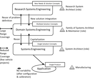
As in the case of the deployment of the systems engineer-ing process, we make the distinction between two types of products, which are different in terms of novelty, purpose, and the amount of reused assets from previous experiences: research systems engineering projects (R&AE) - which pro-pose improved, new designs and architectures for existing problem definitions, and aim for the creation of prototypes; and commercial vehicle SE projects - system designs for com-mercial vehicles, where solution and problem definitions are usually well explored and documented in the Domain Sys-tems Engineering, and thus provide opportunities of reuse. The organization of models and processes for families of sys-tems is presented in figure 2, corresponding to the context of Renault systems engineering. A common repository would allow easy reuse of specifications from upstream research to downstream vehicle projects. Currently, support for vari-ability for MBSE is only applied for research projects in order to provide valuable feedback for the application on a larger scale. By assessing the methodology and tools on a
exploratory case studies (such as the EPB, the automatic lighting system) and validation case studies (the automatic parking assistant) we intend to understand what the chal-lenges are for deployment on a larger scale.
A typical system design scenario (Systems and Research
Figure 2: Organization of product line models and processes for MBSE
Systems Engineering) relies on the systems engineering pro-cess and tools, with specific activities for the management of variability and reuse. There are three main types of activi-ties: (a) searching and reusing assets in the domain models (repository), (b) defining new system assets and (c) updat-ing domain models to reflect changes. Each of these types of activities has specific problems due to the complexity in-duced by the ”spatial system family dimension”. Developing the system domain by updating models (activity type c), provides a convenient way of capitalizing information for later reuse. However, because the assets usually target only a few vehicle projects (upper level system configurations), there is a drawback concerning the reduced reusability of assets across the family of systems.
Domain Systems Engineering activities address the develop-ment and definition of reusable assets: definition of reusable collections of requirements, functions and components; de-velopment of product platforms, which will provide the base for future applications; development of reusable structures with functionality (modules). The development of such as-sets requires an upfront investment [4][28], which does not address directly immediate industry issues and customer needs.
2.3
Constraint based representations for
vehi-cle configuration
At the core of product line engineering practices is con-straint programming [22], [20], [3], which enables both the representation and the analysis of product line models. At Renault, the documentary language [2] enables the descrip-tion of variability on the vehicle level, as described in figure 3. Astesana et al.[2] describe the way variety (or ”diversity”) is expressed and exploited at Renault (and probably in many similar customization oriented applications): as constraint satisfaction problem variables. Different business activities occur at different times in the lifecycle of a vehicle range:
modeling and documentation of the product range, design processes, management of the bill of material, online ex-ploitation by customers (through the online configurator). All of these activities need to rely on the same constraint based description of the product line [2]. This is indeed the aspect addressed by all variability models, which is essential for the derivation of a single system model. Furthermore, constraints are introduced through the commercial offer and stakeholder requirements, but also due to technical, archi-tectural dependencies. Technical constraints are the result of dependencies to variable resources from within the system or from external enabling systems.
Not only do these technical constraints need to be taken into account during derivation, but they may, sometimes, need to be rendered visible for the commercial offer or on organization level. At Renault, features visible on an orga-nization level are introduced under the authority of a group that manages the ”product diversity”. Enabling the system engineer to represent architectural constraints in relation to variability mechanisms becomes a necessity for dealing with the complexity introduced by variability.
Figure 3 presents the visibility perimeters for variability: (i) vehicle level variability (documentary language) - which is used for structuring the commercial offer and defining ve-hicle features and (ii) per system family variability, which defines variations for different systems and share only a re-quired part of the variations with the previous perimeter. In general, once that variability dependencies between systems have been identified, which impact vehicle configuration dur-ing manufacturdur-ing, these dependencies need to be rendered visible on the vehicle level, either by defining new features, or just by adding new constraints. More fine grained visibility
Figure 3: Variability visibility and application perimeters
perimeters are also defined for the documentary language, in respect to different business processes, but this is out of the focus of our systems engineering perimeter. The variabil-ity expressed here, follows the ”version-option” model and partitions variables in two sets:
• Major variables define the main configurations of a particular vehicle model (referred to as ”version”). • Other variables define vehicle features which depend
on the particular model, and thus on the configurations described by major variables.
Constraints are then expressed in two manners:
• Major constraints are expressed as explicit configura-tions, usually as tables.
• Option constraints relate non-major variables to par-ticular (partial) configurations defined by major con-straints.
As systems engineering progressively takes into account vari-ability, both the tools and existing knowledge for mass cus-tomization need to remain compatible and even provide a base for new MBSE tools. Variability expression for fam-ilies of systems, which is then applied in the case of the electric parking brake model, is explained in Section 3.
3.
MODELING TECHNIQUES AND TOOLS
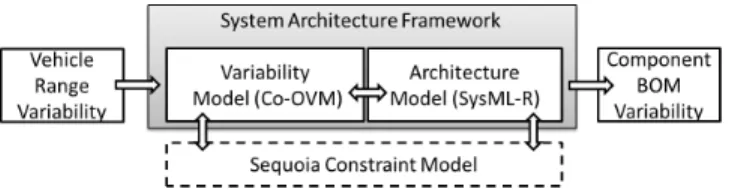
The modeling tool which implements the system archi-tecture framework presented in Figure 1 is based on the Papyrus SysML modeler, while support for variability mod-eling relies on the Sequoia [26] plug-in. Sequoia enables the representation of constraints related to variability in UML/SysML models. As Figure 4 suggests, both variability and system architecture have Sequoia support for constraint modeling :
• The constraint oriented OVM 3 (Co-OVM) variability
model supports configuration activities and specifica-tion of variability in relaspecifica-tion to the organizaspecifica-tion ”docu-mentary language” from vehicle to components. Here, Sequoia [26] constraints enable the representation of dependencies between variants.
• Architecture elements which are concerned by variabil-ity have an impact on other system elements through structural or functional dependencies. It is sometimes possible to infer which elements are optional based on the semantic relationship between elements. Some of the UML semantics are already supported by the Se-quoia tool and we intend to add new inference rules specific to the Renault systems architecture model, but whenever automatic reasoning is not available, it is possible to introduce Sequoia constraints directly in the system architecture model.
Figure 4: System Architecture with variability man-agement modeling tools structure
There are also different types of constraints in relation to variability, which we usually represent on separate diagrams: • Marketing Constraints: are defined by the product de-partment in order to describe the commercial offer. These are imported into the work space at the begin-ning of the project from the documentary language (also called vehicle level variability, in Figure 3). • Operational Constraints: refer to behavior of the
sys-tem in interaction with its environment. Because vari-ability is also present in the environment, the response of the system may be required to be different (e.g. dif-ferences in regulation)
3
Developed in the context of the MBSSE project, in col-laboration with the CEA LIST, based on the UML modeler Papyrus - http://www.eclipse.org/papyrus/
• Technical Constraints: capture dependencies related to design alternatives. Sometimes these constraints have a global impact and need to be made visible in commercial offer. For example, the GPS navigation system requires a CD player, on certain vehicle models, which is a marketing constraint, that has its origin in the design of the system, where maps could be read from CD support.
• Supplier Constraints: availability of certain compo-nents can depend on the country of commercializa-tion, or differences in the characteristics of the supplied components may require other adjustments in the de-sign of the system.
• Vehicle project constraints : describe constraints spe-cific to each vehicle model for which the system shall be designed and deployed.
3.1
Constraint oriented orthogonal
variabil-ity model (Co-OVM)
While the documentary language, covers many of the ve-hicle and context characteristics needed for veve-hicle config-uration, we need to cover more detailed variability infor-mation during system design. The model implemented in our system architecture framework is centered around the concepts of variation point and variant, concepts defined in the OVM model [21]. A variation point regroups sev-eral variants. Constraints between multiple variants belong-ing to different variation points, can be represented (e.g. A ⇒ (B ∨ C ∨ D ∨ . . . ); (A ∧ B ∧ C ∧ . . . ) ⇒ D; where variants A, B, C, D ... belong to different variation points), based on Sequoia [26], which is why we adopted the Co-OVM acronym [10]. Other concepts, which allow integration to the system architecture models and to the organization context, are presented in the current section.
• The Studied diversity represents a partial configura-tion of a system that refers only to: the system envi-ronment, system technical context, and final customer requirements (commercial offer). The studied diver-sity is specified in the operational analysis phase of the system development. Alternatively (at Renault), it is received as input in a specific format (configura-tion tables).It represents the variability that needs to be studied and taken into account for the system de-velopment.
• Types of variability distinguish between variation points that capture different types of information : diversity (stakeholder visible variability) , design (decisions), and components (replaceable COTS, different suppli-ers). By distinguishing among the different types of variability, we aim to prepare the extension of our tool with techniques to enable decision making and trade-off analysis for the system design alternatives [9].
• Variability viewpoints allow for easier navigation of variability in complex system models and also play a methodological support role during configuration [11]. We usually perform a staged configuration that fol-lows the different viewpoints allowing the engineering
to refine and validate the system model. While the predefined list of viewpoints can be customized, we consider the following: documentary language (vehi-cle features), stakeholder requirements, system envi-ronment, operational scope, system technical context, architecture alternatives, functional variability, alloca-tion alternatives, physical variability.
• Variability source, ensures traceability in respect to where it appeared initially in the system analysis. For example variants imported at the beginning of the anal-ysis are traced to the ”documentary language”. It is also possible to specify the details of the cause by pointing to the part of the concerned part of the model, or by documenting the rationale behind the existence of the variation.
• Variation forms characterize system elements to de-scribe in which way they are variable: presence/absence, replacement, parameter, variability impact.
• Vehicle Project describes the constraints specific to the vehicle model which will integrate the system. A sys-tem (with variability) is designed for multiple vehicle models.
• The Diversity Use Case can be associated to any model element, but it is typically used for physical compo-nents. It consists of a logical constraint that restricts the set of possible system configurations, such that, if the constraint is added to the product line constraints model, the given system element is always included. This constraint expression can be deduced from the variability model and the dependencies to the consid-ered model element.
Contrary to the case of many product line models, there is no clear distinction between ”mandatory” or ”optional”. It is the definition of the vehicle range, which establishes which features are optional, mandatory, or ”by default” (if the cus-tomer expresses no preference) for each context or country. For example, the ABS (anti-lock braking) may be manda-tory if the configuration of a vehicle is done for the EU, or may be optional for countries with less restrictive regulation. From an engineering point of view, it is the variable charac-ter of the marketing vehicle features that needs to be taken into account for the design of the system to accommodate this variability, and thus the optional/mandatory character of variability is represented outside the scope of the system framework.
3.2
A flexible configuration process for SysML
models
Product line derivation requires methodological and tool support, being an error prone and complex task. Derivation can also be regarded as a decision making activity [8], where the engineers take into account existing or new alternatives to reach a complete definition of the product. Furthermore, it is essential that the activities needed to perform product derivation integrate into the process and methodology of the organization.
We have focused our example on a common scenario for the automotive industry, where carry-over and carry-across techniques are used to reduce costs and accelerate the de-velopment cycle - dede-velopment by reuse [11].
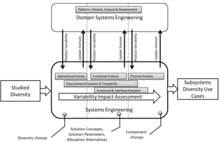
Figure 5 presents a few more details on the activities per-formed during derivation. The derivation is done in stages, by taking into consideration viewpoints presented in Section 3.1. Depending on the phase of the process, reuse choices may be of different nature - high level vehicle characteristics and environment interaction alternatives (diversity), engi-neering choices related alternative designs or specific com-ponent selection from suppliers. The input of the process
Figure 5: Derivation process viewed from a MBSE perspective
determines the perimeter of the diversity context : vari-ants concerning the environment and technical context, that should be covered by the system solution. The output shall document diversity use-cases for components or subsystems (in which diversity context they can be used). The process can be repeated on each level of decomposition, each time the applicability of the system solution, or component (the configuration information) being expressed in respect to the upper level system.
During the modeling activities, variability impact needs to be evaluated in requirements, function and component hi-erarchies, and through allocation. Dependencies between components stem from the ability of each component to pro-vide the required functions in relation to the other system resources.
The type of project has a direct impact on the amount of reusable elements from the family of systems model: re-search projects focus on providing alternative solutions to existing contexts and needs (reuse of operational analysis el-ements), while typical commercial vehicle applications may benefit from existing elements during all the phases of the development process.
4.
ELECTRIC PARKING BRAKE SYSTEM
VARIABILITY
The Electric Parking Brake (EPB) System is commonly used by automotive companies to replace or improve the functionality of the conventional parking brake system [24]. We have used this system in conjunction with the ”hill start assistant” function of the vehicle, as an exploratory case study [12], for exploring development scenarios and iden-tifying requirements for system variability management. In-deed, the complexity as well as the cases it reveals made this a suitable example. It contains variations on all levels
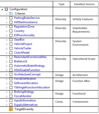
: the service provided and in the way it interacts with the user and it’s environment, design alternatives taking into account force repartition between the electric and hydraulic brakes, architecture or function allocation alternatives. Fig-ure 6 presents the list of variability points in the EPB model. We will present a few examples of diagrams from our case study and discuss each of the viewpoints in respect to the variability it contains.
Customer visible variability corresponds to the variability
Figure 6: Electric Parking Brake list of variation points (screen capture from the RVU (Renault Vari-ability Unit) Papyrus plug-in)
stemming from the vehicle level. This is defined by the prod-uct division. Three types of service are proposed: Manual, Automatic and Assisted4. The ”manual” brake is controlled by the driver either through the classical lever or a switch. The ”automatic” parking brake system variant may enable or disable the brake itself depending on the situation: for ex-ample when the driver leaves turns off the engine and leaves the vehicle, the parking brake is activated. The ”assisted” brake brings extra functions that aid the driver in other sit-uations : such as assistance when starting the car on a slope. In all operational scenarios, except for the manual variant, the system can decide to lock the parking brake. This is for instance the case when the driver exits the car, engine is stopped, the vehicle starts on a slope.
The operational viewpoint contains different facets of the system context, such as: system boundary variability, en-abling systems and vehicle environment. The gear-box and the presence of certain types of trailers (VehicleTrailer vari-ation point) and their characteristics have a direct impact on the internal behavior of the EPB system. The presence of a trailer, for example, may require that the hill start
as-4
The variability presented here does not necessarily use the same nomenclature and expose the same options as current online product catalogs.
sistance functionality be disabled, or its behavior adapted to the new total weight conditions.
The architecture alternatives and allocation alternatives view-points specify design decisions that impact the whole or parts of the technical solution.
This includes: main solution alternatives (ArchitectureCon-cept ), choices on how to distribute the effort among the EPB and the main hydraulic braking system (ForceDistri-bution variation point), decision on software allocation to hardware (SoftwareAllocation variation point) and the allo-cation of the slope angle detection function (TiltAngleFunc-tionAllocation). Allocation of this last function to a specific computer would obviously require that the computer (ECU) already exists.
The variability entailed by the system internal behavior view-point impacts the states and transitions of the system phys-ical and software components.
In the EPB , the braking strategy can vary depending on the deriving conditions. Each strategy requires specific formation: Comfort and Dynamic require vehicle speed in-formation (VSpeed ) and the specific strategy for hill start assistance requires that there is a tilt angle sensor. Braking pressure is monitored after the vehicle has stopped for a cer-tain amount of time (Temporary) for the single DC motor, puller cable solution, and permanently monitored (Perma-nent) for the other solutions.
The variability entailed by the physical architecture specifies variability in component decomposition, through optional or replaceable components, as well as physical interfaces vari-ability between components.
Physical variability of the EPB consists in the presence of different means of applying the brake force: electric actua-tors mounted on the calipers or single DC motor and puller cable much like the traditional mechanical parking brake. Also the type of sensors available may vary depending on the configuration and needs.
In addition to variation points and dependencies, variants attributes were associated to the different variants, in or-der to specify supplementary needed information regarding the impact of PL configuration on performance (Braking Force Dissymmetry, Response Time on Brake), reuse (Vehi-cle Range Coverage) or cost increase in respect to a refer-ence configuration of the system (Extra Engineering Cost). These attributes are numerical variables, that serve during the derivation process and help the engineers make the right choices, by assessing the impact of their choices on the sys-tem configuration, and as the basis for supplementary con-straints.
The instance on the right corresponds to a ”puller cable” technical solution (ArchitectureConcept - PullerCable), while the instance on the left corresponds to the solution based on ”electric actuators” (ArchitectureConcept - ElectricActu-ators). Figure 7 presents two examples of physical configu-rations of the EPB system.
5.
EXAMPLES FROM THE ELECTRIC
PARK-ING BRAKE SYSTEM MODEL
The SysML diagrams associated to each viewpoint follow the methodology proposed by Chal´e et al. [15]. We present a few representative diagrams in this section.
The variants are represented as stereotyped UML Use Cases. Others have taken a similar approach for UML integration
Figure 7: The Electric Parking Brake system main design alternatives (PullerCable and ElectricActua-tor variants are required)
of OVM: Halmans and Pohl [16], von der Maßen and Lichter [27]. At the same time, representation of constraints is based on Tessier’s Sequoia [26] tool.
The studied diversity, presented in Figure 8, captures the variable characteristics of the vehicle and environment that are to be taken into account for the development of the sys-tem: vehicle projects (we refer to them in this article as project A and B), gear box type, regulation which impacts the usage of the system (e.g. regulation requires that a man-ual release of needs to be provided). The list is limited to
Figure 8: Studied diversity - optional context fea-tures that define the scope of the study
elements defined in the company ”documentary language” (vehicle level variability), introduced in 2. Variability in the environment and interactions with external systems is fur-ther refined during the operational analysis. Some of the constraints between these variants remain external to the system variability model and are checked against the docu-mentary language definitions. The separation of organiza-tion level variability from the variability of each system fam-ily provides more flexibility in modeling and reusing mod-eling artifacts to the engineer, and at the same time avoids increasing complexity of the ”documentary language”, by in-troducing new variables.
In the case of the EPB system, we identified 36 constraints between variants. In addition, 44 constraints are issued in the system model, for binding variants to system model items and due to impact of variability. For example the ”comfort braking” strategy can only be implemented on the
solution with two electric actuators mounted on the wheel calipers. These allow sufficient control over the brake pres-sure to implement this particular strategy, thus the following constraints is added :
Comf ort ⇒ ElectricActuators .
The interactions with external actors - the user or other systems - are studied during the operational analysis and represented as sequence diagrams, among other representa-tions [15], which may also contain variable elements. These constraints added by the user are completed by constraints generated by dependencies between system architecture ele-ments and variants (binding), as well as those generated by the Sequoia [26] variability propagation functionality. Vari-ability propagation takes into account the semantics of the Renault system engineering meta-model, and enables the identification of optional elements based on already existing ones.
The functional analysis uses representations that illustrate the interaction and flows between functions, but also the function decomposition as presented in Figure 9. This
con-Figure 9: Electric Parking Brake functional decom-position
Assist-SlopeStart, HoldHydraulicBrake, ProgressiveRelease, Com-fortBrake, and functions rendered optional by existing vari-ability - FastRelease. For instance, HoldHydraulicBrake is only considered if the assistance during hill starting relies on the hydraulic brakes. (functionality also known as ”full hill start assistant”). The FastRelease function is available regardless of the braking system used, but is rendered op-tional by the higher level function, which is also opop-tional. The automatic propagation can provide valuable support during modeling, minimizing the number of explicit asso-ciations of system elements to variants. The same type of reasoning is applied for the allocation of requirements and functions to physical components: (i) optional stereotype: if at least one of the functions allocated to a component is op-tional, then the component is optional; (ii) constraint: the component is excluded if all allocated functions are absent. We still lack support for some of the rules related to our systems engineering meta-model and modeling all binding of variants to the system elements is a time consuming task.
6.
CONCLUSION
Product lines provide valuable theoretical foundations for managing variability in organizations and migrating towards a product line practice may be done for several reasons: overall cost reduction [28], market demand and competi-tion, introducing flexibility for the design of new products. The theoretical foundations of product lines can be adopted in systems engineering, where models like SysML are used to describe system requirements and architecture. We pre-sented our approach for adopting the product line paradigm in systems engineering, while retaining compatibility with legacy information systems (e.g. ”documentary language”) and existing processes. The SysML modeler Papyrus pro-vides a practical research tool, with all the benefits of the Eclipse ecosystem, which enabled us to test the new concepts on pilot projects like the EPB system, which was described briefly in this article.
We were confronted with two types of challenges. The first concerns the modeling activities, in particular the need to express more complex constraints which are often present in the definition of the vehicle range. While we are able to represent the needed constraints with our tool through UML/SysML models, textual representations of complex prod-uct line constraints could be a good and flexible solution. Also better support for the assessment of the impact of vari-ability is needed, coupled with a well documented system model, which would support propagation of optional ele-ments from requireele-ments down to the physical components (through dependencies, allocation, traceability etc.) One particular example are the the sequence diagrams, where we need to manually specify ”optional” elements contained in-side an ”optional” Combined Fragment.
From a methodological point of view the challenge was due to the existing ”diversity” culture already present in the or-ganization: our purpose was to extend variability manage-ment to model based systems engineering in order to reuse specifications, but also for early specification of vehicle com-ponent configurations. We believe this scenario was different from the typical ”migration to product lines” (or adoption scenario), and we are faced with some challenges specific to large organizations. The last two are apply in general to model based systems engineering practices as well as
prod-uct lines:
• Putting product line into context, harmonizing sys-tems engineering practices with existing variability man-agement related activities;
• Overcome ”cultural” barriers to change. On the one hand, adopting new practices does not always allow preservation of previous organizational structures or activities, as responsibilities and tasks may overlap. On the other hand, it may require a shift in the prac-tices of employees and is sometimes met with a ”change resistance” attitude. One solution can consist in courses on product lines, available for employees to ease the adoption of new concepts.
• Overcome ”visibility” barriers to change. Rather than an organization culture/habit, visibility on the com-pany activities is different for each employee, which may lead to a lack of understanding of the strategies and their rationale.
We believe many of the lessons presented by product lines may be generalized for other contexts. In order to suc-cessfully adopt systems engineering in mass customization industries, it is imperative that this includes activities for variability management. Product Line Engineering has also become a subject of focus for the INCOSE [1] and for it’s french chapter AFIS (Association Fra¸caise d’Ing´enierie Sys-t`eme), with an active working group on product lines. System models represent an efficient tool for the support of systems engineering activities. Meanwhile, variability mod-eling techniques which conform both to domain and organi-zational context requirements, can become an efficient and necessary tool for approaching complexity, in large organi-zations which develop customized products.
From the perspective of complex systems many subjects re-lated to product lines still deserve to be explored: assessing the impact of variability across a family of systems or sys-tem of syssys-tems, supporting design decisions in respect to context and component variability. The derivation process also proved to be time consuming and cumbersome, with the complexity of the product family quickly rising even for sys-tems like the EPB. While we approached the methodological aspects of the derivation process in respect to systems engi-neering [11], we intend to explore how we can improve and guide derivation through recommendation, in respect several aspects: for example, the required time (computation time and configuration steps) [19] and to engineering objectives related to system properties.
7.
REFERENCES
[1] Focus on product line engineering. INCOSE Chicagoland Chapter Newsletter, 1(2):2, 2011. [2] J. Astesana, L. Cosserat, and H. Fargier.
Constraint-based modeling and exploitation of a vehicle range at renault’s: Requirement analysis and complexity study. In Workshop on Configuration, page 33, 2010.
[3] D. Benavides, S. Segura, and A. Ruiz-Cort´es. Automated analysis of feature models 20 years later: A literature review. Information Systems,
[4] G. B¨ockle, P. Clements, J. D. McGregor, D. Muthig, and K. Schmid. Calculating ROI for software product lines. IEEE Software, 21(3):23– 31, June 2004. [5] H. G. Chal´e G´ongora, A. Dauron, and T. Gaudr´e. A
commonsense-driven architecture framework. part 1: A car manufacturerˆa ˘A´Zs (na ˜A´rve) take on mbse. In INCOSE 2012.
[6] D. P. Clements and L. M. Northrop. Software Product Lines: Practices and Patterns. Prentice Hall, 2002. [7] A. Dauron. Model-based powertrain control: Many
uses, no abuse. Oil & Gas Science and Technology – Rev. IFP Oil & Gas Science and Technology – Rev. IFP, 62(62):427–435, 2007. [8] O. Djebbi, C. Salinesi, and D. Diaz. Deriving product
line requirements: the RED-PL guidance approach. In Software Engineering Conference, 2007. APSEC 2007. 14th Asia-Pacific, pages 494 –501, Dec. 2007.
[9] A. Doufene, H. Chal´e G´ongora, and D. Krob.
Complex systems architecture framework. extension to multi-objective optimization. Paris, Dec. 2012. [10] C. Dumitrescu, P. Tessier, C. Salinesi, S. G´erard,
A. Dauron, and R. Mazo. Capturing variability in model based systems engineering. In Complex Systems Design & Management, Paris, Dec. (forthcomming) 2013. Springer Berlin Heidelberg.
[11] C. Dumitrescu, P. Tessier, C. Salinesi, S. G´rard, and A. Dauron. Flexible product line derivation applied to a model based systems engineering process. In M. Aiguier, Y. Caseau, D. Krob, and A. Rauzy, editors, Complex Systems Design & Management, pages 227–239. Springer Berlin Heidelberg, 2013. [12] S. Easterbrook, J. Singer, M. anne Storey, and
D. Damian. Selecting empirical methods for software engineering research.
[13] R. Faure and A. Dauron. Ing´enierie renault et ing´enierie des syst`emes. In Journ´ee Th´ematique AFIS ”Strat´egies d’Entreprises en Ing´enierie Syst`eme”, Paris, June 2009.
[14] J. Filho, O. Barais, B. Baudry, and J. Le Noir. Leveraging variability modeling for multi-dimensional model-driven software product lines. In 2012 3rd International Workshop on Product Line Approaches in Software Engineering (PLEASE), pages 5 –8, June 2012.
[15] H. G. C. G´ongora, T. Gaudr´e, and
S. Tucci-Piergiovanni. Towards an architectural design framework for automotive systems development. In M. Aiguier, Y. Caseau, D. Krob, and A. Rauzy, editors, Complex Systems Design & Management, pages 241–258. Springer Berlin Heidelberg, Jan. 2013. [16] G. Halmans and K. Pohl. Communicating the
variability of a software-product family to customers. Software and Systems Modeling, 2(1):15–36, 2003. [17] K. C. Kang, S. G. Cohen, J. A. Hess, W. E. Novak,
and A. S. Peterson. Feature-oriented domain analysis (FODA) feasibility study. Technical report, DTIC Document, 1990.
[18] D. Krob. El´ements d’architecture des syst`emes complexes. In A. Appriou, editor, Gestion de la complexit´e et de l’information dans les grands syst`emes critiques, pages 179–207. CNRS, 2009. [19] R. Mazo, C. Dumitrescu, C. Salinesi, and D. Diaz.
Recommendation heuristics for improving product line configuration processes. In (submitted for)
Recommendation Systems in Software Engineering. 2013.
[20] R. Mazo, C. Salinesi, D. Diaz, O. Djebbi, and A. Lora-Michiels. Constraints: The heart of domain and application engineering in the product lines engineering strategy. International Journal of Information System Modeling and Design (IJISMD), 3(2):33–68, 2012.
[21] K. Pohl, G. B ˜A˝uckle, and F. J. v. d. Linden. Software Product Line Engineering: Foundations, Principles and Techniques. Springer-Verlag New York, Inc., Secaucus, NJ, USA, 2005.
[22] C. Salinesi, R. Mazo, D. Diaz, and O. Djebbi. Using integer constraint solving in reuse based requirements engineering. In Requirements Engineering Conference (RE), 2010 18th IEEE International, pages 243 –251, Oct. 2010.
[23] C. Salinesi, R. Mazo, O. Djebbi, D. Diaz, and A. Lora-Michiels. Constraints: The core of product line engineering. In 2011 Fifth International Conference on Research Challenges in Information Science (RCIS), pages 1 –10, May 2011.
[24] K. Sl´osarczyk, J. G. Linden, K. J. Burnham,
K. Cockings, and R. Capolongo. Implementation of an electronic park brake feature with limited data availability. pages 254–259. IEEE, Aug. 2008. [25] I. Sommerville. Systems engineering for software
engineers. Annals of Software Engineering, 6(1):111–129, 1998.
[26] P. Tessier, D. Servat, and S. Gerard. Variability management on behavioral models. In VaMoS Workshop, pages 121–130, 2008.
[27] T. von der Maßen and H. Lichter. Modeling variability by UML use case diagrams. In Proceedings of the International Workshop on Requirements Engineering for product lines, page 19ˆa ˘A¸S25, 2002.
[28] D. M. Weiss and C. T. R. Lai. Software product-line engineering: a family-based software development process. Addison-Wesley Longman Publishing Co., Inc., Boston, MA, USA, 1999.
![Figure 1: Summary of viewpoints in our SE archi- archi-tecture framework [9]](https://thumb-eu.123doks.com/thumbv2/123doknet/13336939.401300/4.918.484.803.216.454/figure-summary-viewpoints-se-archi-archi-tecture-framework.webp)