A DEVICE FOR MEASURING COMPRESSIVE STRESS IN CONCRETE
by
Roy W. Carlson
A.B. University of Redlands M.S. University of California
1922 1933
Submitted in Partial Fulfillment of the Requirements for the
Doctor of Science Degree
from the
Massachusetts Institute of Technology
1939 Signature of Author Signature of Professor in Charge of Researeh Signature of Chairman of Special Committee Jr u - - -,, -- V -- u - ASu
I
I I I f-Belmont, Massachusetts May 10, 1939
Professor G. W. Swett Secretary of the Faculty
Massachusetts Institute of Technology Cambridge, Massachusetts
Dear Sir:
In partial fulfillment of the require-ments for the degree of Doctor of Science, I submit herewith my thesis entitled "Development and Analy-sis of a Device for Measuring Compressive Stress in Concrete."
Respectfully submitted,
Roy W. Carlson
I. INTRODUCTION . . ... 3
A. The Need for a Stress-Measuring Device . 3 B. Why Measurements of Deformation are Made 7 II. DEVELOPMENT OF STRESS METER . . . 12
A. Conception of the Stress Meter . . . 12
B. Early Designs of Stress Meters . . . 16
C. Present Form of Stress Meter . . . 19
III. ANALYSES OF BEHAVIOR OF STRESS METERS IN CONCRETE ... 26
A. Purpose of Analyses . . . 26
B. Method of Analysis . . ... 31
C. Results of Analyses .... . . . 44
IV. DESIGN CONSIDERATIONS . . . . . 52
A. Sensitivity and Range as Governed by Internal Plate . ... ... .... . .. 52
B. Effect of Temperature on the Stress Meter . . . .. . . . 53
C. Considerations Regarding Modulus of Elasticity . . . 59
MEASURING COMPRESSIVE STRESS IN CONCRETE
Abstract
A 12-year development of a device called a "stress meter" is described. This device is shown to be capable of
indicating compressive stress in concrete substantially inde-pendent of differences in deformation between the device and the concrete in which it is embedded.
The stress meter is a fluid-filled diaphragm, so designed that the pressure in the fluid is always substan-tially equal to the pressure of the surrounding concrete ly-ing against the faces of the diaphragm. The fluid is in con-tact with a small internal plate, which is deflected elasti-cally in direct proportion to the intensity of stress or
pressure. A small electric strain meter, mounted on one face of the diaphragm, detects the deflection of the internal
plate and by means of conductor cable and testing set indi-cates the deflection and hence the stress at any convenient termination of the cable.
Analyses are described which substantiate the claim that the stress can be indicated with only a small error when the diaphragm tends to remain constant in thickness while the surrounding concrete contracts. The effects of changes in temperature and in modulus of elasticity also are discussed.
I. INTRODUCTION
AL. The Need for a Stress-Measuring Device
The design of concrete structures and the evalua-tion of their margins of safety are based on calculated stresses, not on deformations. Measurements on structures aimed toward determining their safety and the manner in which they support the applied loads have usually been confined to deformations, since stress measurement has heretofore been impossible. From measured deformations, attempts have been made to calculate the stresses in devious ways.
The relation between stress and deformation in a material like concrete is usually complicated by the simulta-neous occurrence of deformations arising from causes other than load. Consequently, the relation is not a simple one. Furthermore, the relation between stress and deformation in-volves the age of the concrete, the duration of the stress, and the magnitude of the stress. Before proceeding with the explanation of a device for measuring direct stress, there-fore, the limitations of measurements of deformation as a means of determining stress will be further outlined. Dis-cussion of these may clarify the need for a separate device for measuring stress.
gradually increases as the concrete hardens and only after a month or more is the modulus substantially constant. That
is to say, the deformation due to the quick application of a given stress becomes less and less as the concrete becomes older. Thus, even for the simple task of computing the mag-nitude of stress which is applied quickly, the observed strain must be multiplied by a modulus of elasticity which depends ulpon the age of the concrete. If this were the only factor to complicate the problem of translating deformation into stress, it would not be too difficult to apply to each ob-served change in deformation the appropriate modulus of elas-ticity, as measured at various ages on specimens of corre-sponding concrete. But there are other complications.
Secondly, there is the abnormal effect of tempera-ture changes upon deformations in concrete. In general,
con-crete expands with each degree of rise in temperature more than it contracts upon cooling, with the result that
alterna-tions in temperature cause a growth" of the dimensions. Furthermore, in the early stages of hardening, there is an additional growth due to hydration of the hard-burned oxides of magnesia and lime that are contained in ordinary cement,
and this growth may make the apparent coefficient of expan-sion as much as 50 to 100 per cent greater for the first rise in temperature than for later heating or cooling. Only if
hard-burned oxides of magnesia and lime is this growth effect ab-sent.
The increased difficulty of translating deformation into stress that is added by these growth"t effects is still not too great. Stress-free specimens of identical concrete
can be provided in cavities within the body of a concrete structure and these specimens will respond to all causes
other than stress. Deformations of these specimens, as meas-ured by means of embedded electric strain meters, can be
assumed to be equal to those of the neighboring concrete of the structure except for the effect of stress. When these deformations are subtracted, therefore, from those observed
at neighboring points of the structure itself, the remainder can be assumed to result only from stress. The stress could then be computed by multiplying this remainder by the appro-priate modulus of elasticity, provided no other factors were operative.
The problem is not yet solved, because there is the plasticity of the concrete to consider. Concrete contin-ues to deform under stress at a rate that depends upon the
age, strength, and intensity of stress. Although the plas-ticity gradually diminishes with increasing age, even after a month of hardening, the plastic deformation that accumu-lates when the stress is continually applied for about two
months will usually be as great as the instantaneous, elastic deformation. After learning that plastic deformation is approximately proportional to the intensity of stress, one can resort to the use of a lower, spurious modulus of elas-ticity, called the "sustained modulus of elaselas-ticity,, and thus translate deformation into stress with automatic allow-ance for plastic flow. The simplicity of this attack is up-set by the necessity of knowing the sustained modulus of elasticity not only for the particular concrete, but also for the particular age, time interval of loading, and tem-perature of hydration Furthermore, the simple expedient of using a sustained modulus of elasticity does not take into account the plastic flow due to stress already existing; therefore, a separate correction must be made for each time
interval. The conversion of deformation into stress must be a step-by-step process, considering one time interval and
then another.
Finally, the contraction of concrete upon drying is so great that whenever drying occurs in appreciable amount, the contraction due to drying is likely to outweigh deforma-tion due to all other causes. Fortunately, the diffusion of moisture from concrete is such a slow process that drying is not a major factor except in thin-walled structures.
translating deformation of concrete into stress might not be too much for the engineer, but the combination of all of them discourages the use of this means of determining stress. The limitations of so-called nstrain" measurements as a means of determining stress were first realized by the writer in 926 during the testing of the full-scale experimental arch dam at Stevenson Creek, California. Strains were measured both in-ternally and on the surfaces of the dam on almost 1000 gauge lines. Although as computed from changes in deformation, the changes in stress due to the rapid filling of the reser-voir were in reasonable agreement with corresponding stresses in an elastic model of the dam, cracking occurred with no apparent relation to the tensile stress of the concrete. In other words, while the rapid change in stress could be learned from the deformation measurements, the actual, existing
stresses were not revealed. It was then that the writer real-ized the need for a device to measure stress substantially
in-dependent of deformation, and he began the development of the "stress meter." Thus, the stress meter has been under develop-ment for about 12 years. Three of the 12 years of developdevelop-ment were spent in the laboratories of the Massachusetts Institute of Technology.
B. Why Measurements of Deformation are Made
avail-able for measuring stress in concrete. Therefore, engineers have resorted to the measurement of deformations by the use of electric strain meters, despite the difficulties of
translating the results into stress.
Measurements of deformation can be of real value in revealing probable changes in stress over short periods of time and at later ages when the concrete has attained a fair degree of elasticity and when temperature fluctuations are small. Designing engineers usually are more concerned with changes in stress due to load than with actual stresses, and in many cases, the deformations give reliable indica-tions of these load-caused changes in stress.
Concurrently with the development of the "stress meter," the writer has developed the so-called elastic-wire electric strain meter, which is now being used almost exclu-sively in this country for measuring internal deformations of concrete. This strain meter, which functions by the
change in resistance of highly elastic wire, seems to be the best device for measuring strain within concrete up to the present time. There was no great difficulty n developing the strain meter as compared with the stress meter, and
therefore only a few years of gradual development were re-quired to make it an accepted instrument. More than 2000 strain meters have been used, although they have never been
advertised for sale. Among the more important structures in which strain meters have been used, may be mentioned Boulder, Norris, Hiwassee, Tygart, and Grand Coulee Dams, Colorado River Aqueduct, and San Francisco-Oakland Bridge. They have
also been used in several foreign countries. One reason for not advertising strain meters for sale has been the belief
that they may eventually be supplanted largely by the stress meter. Also, the interpretation of results from strain meters has been so difficult that it has not seemed wise to encourage
promiscuous installations.
The following brief description of the strain meter is given because this device, in modified form, is an impor-tant part of the present stress meter. An isometric view of the standard strain meter as drawn by Jerome Raphael (now with the United States Bureau of Reclamation)is presented in Fig. 1. From this figure it may be seen that the strain
meter contains two coils of wire looped around porcelain spools. The wire is a very fine size of music wire having a tensile strength in the neighborhood of 700,000 pounds per square inch. The mounting of the porcelain spools on the steel frame is such that existing tension in the outer coil is decreased as the ends of the meter are brought closer to-gether, hile tension in the inner coil is increased. Be-cause of the linear relationship between tension and
(Cover not shown)
CARLSON
ELASTIC WIRE STRAIN METER
DRAWN: J.M.R.
ISOMETRIC VIEW OF
CHECKED: J.E.D. ,-",, I
SUBMITTED: J.E.D.
APPROVED:E S TRAIN METER
APPROVED:
changed in direct proportion to the change in gauge length. Direct measurement of resistance ratio is made by connecting to a testing set so as to form a Wheatstone-bridge circuit in which two of the four arms are in the testing set and the others are in the strain meter. The resistance ratio is not affected by changes in temperature even though the resis-tances themselves are affected. Quite conveniently,
tempera-ture can be determined by a measurement on the same coils of
wire and by means of the same testing set. For this purpose
connections are made so as to permit measurement of the
com-bined resistance of both coils, because as a result of the
compensating effect of any increase of tension in one oil being offset by a decrease in tension of the other, this
re-.sistance is substantially independent of the tensions in the rwires. For further details of the strain meter, reference is made to published papers.1
Carlson, R. W., Five Years Improvement of the Elastic-Wire Strain Meter," Eng. News-Record, May 16, 1935.
Davis, R. E. and Carlson, R. W., "The Electric Strain Meter and Its Use in Measuring Internal Strain," Proc. A.S.T.M., 1932.
II. DEVELOPMENT OF STRESS METER
A. Conception of the Stress Meter
The conception of the stress meter may be appreci-ated most readily from a roundabout explanation. Consider what would happen if a well-defined block of concrete could be cut and removed from the interior of a concrete mass so as to leave a cavity. For convenience, let us define the imagi-nary walls of the block before its removal as the walls of
the "uncut cavity." It will also be convenient later to de-part from the usual definition of the word cavity and to speak not only of an "empty cavity," but also of the cavity filled with an elastic body.
If stress existed in the concrete before the cavity were cut, then when the cut was made, local relief of stress would deflect the walls of the cavity relative to the walls
of the uncut cavity. The walls would be returned to the "un-cut" locations only by the application of exactly the same stress as existed before the cavity was cut. The reasoning is the same if the cavity be assumed to exist before the
stress is applied; if the walls of the cavity were to be sub-jected to just sufficient stress to maintain them nearly
where they would be if the cavity were uncut, the required stress would be nearly the same as that occurring if the
stress on the walls of the cavity would of necessity be nearly that of the undisturbed concrete at that location.
There is nothing startling in this view; it is merely an in-troduction leading up to the otherwise-difficult explanation of how a stress measurement can be almost independent of the magnitude of the attendant strain.
The conditions in the assumed cavity become
inter-esting when the cavity takes the shape of a thin plate or
disc. If no stress is applied to the walls of the cavity,
the flat faces are deflected a relatively large amount by stress in the surrounding concrete. For example, consider a cavity 10 inches in diameter and one-tenth of an inch thick. If a stress of 100 p.s.i. is applied to the surrounding con-crete in a direction perpendicular to the plane of the cavity, the deflection of the midpoint of each face (according to
equations presented later and assuming a modulus of elasticity
of 2,000,000 p.s.i. for the concrete) will be 0.001 inch. If
now the cavity were fitted with a disc of the concrete before the application of stress, the corresponding movement of either face of the disc due to direct strain, would be only 0.000,002.5 inch (.05 inch multiplied by 50 millionths
strain). In other words, the faces of the cavity when empty would be deflected by stress in the surrounding concrete 400
times as much as would the faces when the cavity was fitted with a concrete disc. As a further illustration, if the
cavity were instead fitted with a disc of material twice as compressible as the concrete, the movement of the faces due to stress would still be small, being about 100 per cent more_l than that of the concrete disc, but the excess being onlyi
one-quarter of one per cent of the movement of the faces of the empty cavity. In other words, a disc of material having a modulus of elasticity only one-half that of the concrete, when fitted to the cavity, maintains its faces nearly where they would be were the cavity uncut. The stress through this more-yielding disc would, therefore, be almost exactly the
same as though it had the same rigidity as the concrete. Like-wise, if this particular cavity were fitted with a disc
pos-sessing infinite rigidity, the faces would remain after appli-cation of stress to the surrounding concrete nearly where they would be for the uncut cavity. That is to say, the faces of the filling would not move at all, whereas the faces of the uncut cavity would move 0.000,002.5 inch and the faces of the empty cavity would move 0.001 inch. Thus, the deficiency in movement of the faces of the cavity filled with material of infinite rigidity would be only 1/4 of 1 per cent as much as
the excess of movement of the faces of the empty cavity. It follows that the stress through the non-yielding disc would be nearly the same as-though the cavity were uncut. From these illustrations, the conclusion is reached that the
stress and consequent strain in a thin disc of elastic mate-rial will bear a close relation with the stress but not nec-essarily with the deformation in surrounding concrete.
The stress meter takes advantage of the fact, which will be proved by analyses later, that when a thin plate is cast in concrete, the stress transmitted through the plate normal to its faces must necessarily be nearly the same as
the stress in this direction in the neighboring concrete. Provided it is granted that a thin plate embedded in concrete will accept a stress which is nearly equal to that in the sur-rounding concrete, it is not difficult to visualize how the
plate might be converted into a stress meter. It is only nec-essary then that there be some means of determining the stress through the plate. Mention will be made of means which were attempted in early stages of the development, and of the
means employed in the present stress meter. The early trials are offered as a background for further development of the stress meter, because although the present design appears to promise satisfactory results, better devices will undoubtedly be developed.
B. Early Designs of Stress Meters
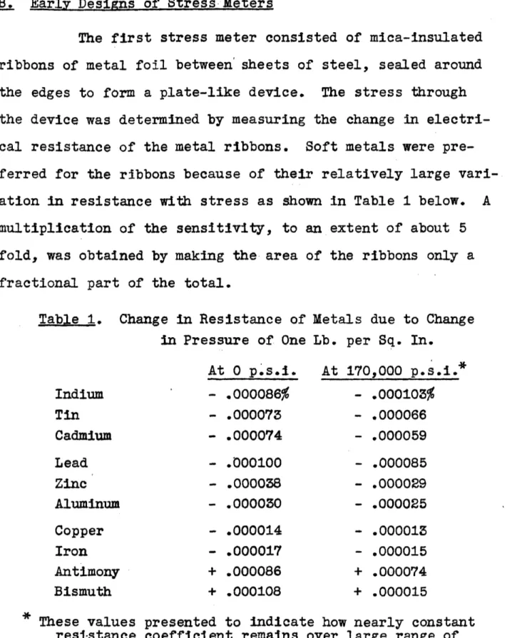
The first stress meter consisted of mica-insulated ribbons of metal foil between sheets of steel, sealed around the edges to form a plate-like device. The stress through the device was determined by measuring the change in electri-cal resistance of the metal ribbons. Soft metals were pre-ferred for the ribbons because of their relatively large vari-ation in resistance with stress as shown in Table 1 below. A multiplication of the sensitivity, to an extent of about 5
fold, was obtained by making the area of the ribbons only a fractional part of the total.
Table 1. Change in Resistance of in Pressure of One
Metals due to Change Lb. per Sq. In. Indium Tin Cadmium Lead Zinc Aluminum Copper Iron Antimony Bismuth At 0 p.s.i. - 000086% - .000073 - .000074 - .000100 - .000038 - .000030 - .000014 - .000017 + .000086 + .000108 At 170,000 p.s.i.* - .000103% - .000066 - .000059 - .000085 - .000029 - .000025 - .000013 - .000015 + .000074 + .000015
* These values presented to indicate how nearly constant resistance coefficient remains over large range of
pressure.
Note:- All values are computed from data in Smithsonian Physical Tables.
The first stress meter gave only enough promise to warrant trial of several modifications. Difficulties were
(1) the sealing of the edges and the design of lead connec-tions, (2) the assurance of initial contact between steel sheets, mica, and ribbon, (3) the elimination of continued plastic flow from the ribbons, (4) the correction for temper-ature changes, and (5) the obtaining of sufficient sensitivity.
Several years after the first stress meter had been abandoned, Dr. P. W. Bridgman of Harvard University suggested
to the writer that he use manganin ribbon and thus eliminate
the need for temperature compensation. As regads the elimi-nation of temperature troubles, the manganin is excellent, because it has almost no resistance change due to temperature. BIut the pressure sensitivity of manganin is low, the change in resistance being only 0.0016% for a change in pressure of 100
p.s.i. A multiplication of sensitivity of more than 100-fold would have to be accomplished to obtain sufficient sensitivity for field measurements, where long lead wires and portable test sets must be used. The local stresses in the materials of the stress meter would be likely to exceed acceptable lim-its if such a large multiplication were to be attempted.
The second stress meter consisted of a sheet of celluloid or bakelite between sheets of steel, with cells of granulated carbon in the celluloid or bakelite. The stress was indicated by change in resistance of the carbon cells.
It was believed that if the design gave sufficient promise, a more suitable material than the celluloid or bakelite could be found. The greatest difficulty was lack of repro-ducibility, presumably due to the instability of the carbon. No granular material can be expected to return exactly to
its original condition after being loaded. Because of this great failing, the scheme was abandoned, despite great sensi-tivity.
The third stress meter employed fine steel wire embedded in a sheet of celluloid, so arranged that stress
through the celluloid sheet would change the stress and resis-tance of the steel wire. This design showed a considerable amount of promise but failings were that the celluloid was not a suitable material because of its high thermal expansion and high Poissons ratio, proper elastic modulus could not readily
be obtained, sensitivity was very low, and temperature com-pensation was difficult. The scheme seemed to offer promise with possible improvement but in view of the indicated large amount of necessary development, the idea was set aside.
The fourth stress meter was a fluid-filled diaphragm with a pressure-sensitive detector located in a cavity
acces-sible to the fluid. The pressure-sensitive detector was a hollow, elastic bulb wrapped with a fine size of elastic wire. Under pressure, the bulb was compressed and the tension and
resistance of the surrounding wire were reduced. The scheme seemed to have more promise than any previously tried but was set aside for future development when a more satisfactory pressure-sensitive detector might be obtained. As it was de-signed, with a detector consisting of a glass bulb wrapped with music wire, the sensitivity was not sufficient and pro-vision for temperature correction was not readily made.
C. Present Form of Stress Meter
The design of stress meter that has offered a con-siderable amount of promise and s now being used in certain modern dams consists of a fluid-filled diaphragm, in which the pressure of the fluid deflects a small internal plate. A cross section of this stress meter is shown in Fig. 2. The
essentials of operation are as follows: When the concrete surrounding a stress meter is subjected to compressive stress which has a component perpendicular to the faces of the dia-phragm proper of the stress meter, the concrete presses
against the faces of the diaphragm. The pressure in passing through the diaphragm, must also pass through the mercury film. The pressure, or compressive stress, is thus converted
into fluid pressure in the mercury film. The fluid pressure, acting in all directions, deflects the internal plate upward, elastically. The elastic deflection of the internal plate is
STRE55 BEINfG MENSURED
Porce/aln spool
S #ra/n me ter un/+ / o be
covered w/h fabric -See/ bar 'A"
rDza/ohragm proper (circular)
/Werc-ury film
I I CI c II /.I p1U t
I,
Cross
Section
Thru Stress Meter
FIa.
directly proportional to the intensity of the fluid pressure, which is in turn equal to the compressive stress applied to
the diaphragm. The deflection of the internal plate is
therefore an index of the compressive stress in the concrete. The deflection of the internal plate of a stress meter is measured by means of a small elastic-wire strain meter mounted in one fact of the diaphragm. As previously
stated, the strain meter contains two electrical-resistance coils (not shown), which are made by looping fine steel wire over porcelain spools, with the wire under a predetermined amount of initial tension. The mounting of the porcelain spools is such that as the deflection of the internal plate increases, steel bar "nA (see Fig. 2) moves upward and the tension and electrical resistance of the strands of one coil increase while the tension and electrical resistance of the second coil decrease. The ratio of the resistances of the two coils increases proportionately as the deflection of the internal plate increases. Because this ratio is independent of the change in resistance due to change in temperature, and because lead wire effects are largely compensating, field measurements of ratio can be made readily to an accuracy of
0.01%. This sensitivity is ample to permit stress measure-ments to 5 p.s.i. or less. Moreover, temperatures can be
indicating the plate deflection, because the combined resis-tance of the two coils varies substantially only with temper-ature and not with deflection.
The essential steps in the functioning of the stress meter are then as follows: (1) Compressive stress in the con-crete subjects the fluid film in the diaphragm of the stress meter to a fluid pressure of an intensity substantially equal
to the component of compressive stress normal to the dia-phragm; (2) The fluid pressure in turn deflects the internal plate by an amount which is proportional to the intensity of the pressure; (3) The deflection of the internal plate moves a steel bar on Which one end of each of two sets of tensed wires are mounted and thus increases the tension in one set
of wires of the strain-meter unit and decreases the tension in the other set, both in direct proportion to the deflection;
(4) The changes in tension in the two sets of elastic wires
changes their electrical resistance ratio in direct proportion
to the changes in tension; and (5) The change in electrical
resistance ratio changes the balance reading or "observed re-sistance ratio" in a special Wheatstone-bridge type of test-ing set which is connected to the strain-meter unit by a 3-'wire conductor; any changes -in the observed resistance ratio denotes a change of stress in the concrete around the stress meter. When it is stated that compressive stress is "measured"
by means of the electrical testing set, or even by means of the stress meter, it should be understood that the measure-ment is indirect to the extent noted in this paragraph. An indication of how closely the stress meter approaches the ideal functioning ust outlined will be provided later in the form of analyses and of actual test results.
The strain-meter unit of the stress meter is cov-ered with cloth to isolate it from the hardened concrete as indicated in Fig. 2. This protects the unit from being dis-torted by volume changes of the concrete and also prevents it from transmitting unwanted stresses to the diaphragm. Be-cause the covered strain-meter unit has a sectional area of less than one square inch, its simulation of a void in the
concrete can be shown to have little effect.
The rim of the diaphragm proper, as shown in Fig.
2, is thinner than the remainder, in order to be somewhat flexible. The rim is covered with cloth to keep it from be-ing in close contact with the concrete. Thus, the rim, like
the strain-meter unit, acts as a stress-free void in the con-crete. In this way is avoided the uncertainty of an unknown amount of stress being taken by the continuous metal rim. Actually, the analyses of behavior to be presented later take
account of the fact that the wrapped rim is stress-free.
which houses the elastic steel wires, while the other is a sealing chamber for the lead-wire terminals. This duplica-tion is purposely made in order that the chamber containing the steel wires can be kept free from all contaminating mate-rial, such as the rubber sheathing of the lead wires. Fur-thermore, it is not easy to make a positive seal at the point where the lead cable enters the metal case. Therefore, the sealing chamber is filled with cable oint compound, a mate-rial derived from coal tar, that is solid at ordinary temper-atures. The elastic-wire chamber is filled with castor oil, which has been found to be the best liquid preventative of corrosion for the steel wires under the prevailing conditions. Besides being a preservative for the steel wires, the castor
oil prevents serious temperature rise of the extremely fine wires during passage of electrical current in the measurement of their relative resistances.
All of the main parts of the strain-meter unit are of steel, including the wires, the frame, and the cover which acts as a part of the frame. The various parts then expand equally, and consequently the thermal expansion of strain meter parts is compensating. It has already been explained that the strain-meter unit is designed so as to permit measure-ment of resistance ratios of the steel wires instead of actual resistances and thus to be compensated also for the effect of
temperature change on electrical resistance. There remains, however, a third effect of temperature for which the stress meter as a whole is not compensated, namely, the thermal
expan-sion of the diaphragm and its fluid film. The last named ther-mal effect is a serious one which is discussed at length later in this thesis.
The proper embedment of a stress meter in concrete at time of casting is important, especially when the stress meter is to be placed horizontally to measure vertical stress.
Changes in thickness of the diaphragm are not many millionths of an inch under most conditions and therefore the contact with the concrete must be good. The bleeding, or tendency of water to rise to the surface of concrete as solid particles settle, must be substantially zero or a water film will collect on the under side of the stress meter diaphragm before the concrete hardens. The most satisfactory procedure seems to be, before embedding the stress meter to wait until the concrete has be-gun to stiffen and all bleeding has stopped. A flat surface
Its made at the proper depth in the concrete and the bottom side of the diaphragm is "bedded" into this surface. Then the remainder of the stress meter is carefully covered with con-crete and the lead-wire cable is carried to the desired termi-nal point or switchboard.
III. ANALYSES OF BEHAVIOR OF STRESS METERS IN CONCRETE
A- Purpose of Analses
The behavior of a stress meter in concrete is fully defined by two actions which may be considered separately. Firstly, there is the simple action when the concrete and
dia-phragm tend to compress equally. Secondly, there is the ef-fect of unequal dimensional changes due to whatever cause, or in other words, the common case where the thickness of the diaphragm tends to change by a different amount than does an equalthickness of adjacent concrete. The unequal dimensional changes may be due to a variety of causes, of which the most important are (1) unequal thermal expansion of concrete and diaphragm, (2) unequal moduli of elasticity, (3) plastic flow of concrete, and (4) shrinkage or growth of concrete. When the moduli of elasticity, or compressibilities, of diaphragm and concrete are not equal, the case can be treated as though the compressibilities are equal but that either the diaphragm or the concrete has a contraction or expansion in addition. Thus an analysis of the effect of unequal dimensional changes
provides the basis for all departures from the ideal action in which the diaphragm and concrete tend to compress equally.
It has already been explained that when the appli-cation of stress causes the concrete and the stress meter
diaphragm to compress equally (disregarding the effect of the wrapped rim for the present), it is inevitable that each be under the same stress. The fluid in the diaphragm then
re-ceives the full compressive stress of the concrete and the internal plate is deflected a corresponding amount. For this idealized case, the-shape of the diaphragm is of no conse-quence because whatever the shape, the diaphragm simulates the concrete and is equivalent to the concrete it replaces as far as stresses are concerned. This suggests at once the desirability of making the compressibility of the diaphragm at least approximately equal to that of the concrete.
The shape of the stress meter becomes important, however, when differences in deformation of stress meter and
concrete are involved. If the concrete shrinks, for example, some compressive stress will be applied to the diaphragm by the shrinking concrete, although there may have been no stress in the surrounding concrete. Similarly, if the concrete is more compressible than the diaphragm, then when the concrete
is loaded, the extra contraction of the concrete will apply an extra compressive stress to the diaphragm. Thus, whenever the diaphragm and the concrete tend to compress unequally, there will be an error in the stress indicated by the stress meter. The amount of this error is closely related to the
as well as to the extent of the difference in deformation. If the diaphragm is thin, the error will be small, as will be proved below.
As a preliminary to actual analyses, an attempt is made in Fig. 3 to demonstrate the fact that only a small stress can be thrown on the stress meter diaphragm when sur-rounding concrete contracts. This illustration is made up of three parts, (a) a cross section of a half of the stress meter diaphragm to natural scale, (b) a partial cross section of the half diaphragm to greatly magnified vertical scale (about
7000 times) so as to portray an assumed concrete contraction, and (c) a repetition of (b) but showing also the extent of the absurdity that results if the :c ontracting concrete is assumed to compress the diaphragm to the full extent of the contrac-tion desired by the concrete; i.e., the amount the diaphragm would contract if it were concrete.
Fig. 3c shows why the shrinkage of concrete around a stress meter diaphragm subjects it to very little stress. The figure shows that the shrinking· concrete can be "warped" around the diaphragm by a relatively small reaction from the diaphragm. This figure is based on an assumed shrinkage of
100 millionths of an inch per inch. If the diaphragm were to be compressed by this full amount, the stress through the diaphragm would necessarily be 200 p.s.i., because the effec-tive modulus of elasticity of both diaphragm and concrete is
diaphragm -on trac tion
-Contracon assumed
18.7m//-ionths inch = OO/ mnl. in per in.
b. ariol ecfhon -~o Enlarged ¥erlict cale
/~~~~~~~~~~~~~~~~~~~~~~~~~~~~~~~~~~~ /~~~~~~~~~~~~~~~~~~~~~~~~~~~~~~~~~ /~~~~~~~~~~~~~~~~~~~~~~~~~~~~~~~~~~~~~~~
/ ~~ -
/---Rn,,indarv nfrnntrrpI ;f if i5 n
exr
fnrre of 200 n.sIragm and concre/e i/h contracted
boun-y force of 200 p.s i.
3c. Absurd Condition which Develops
if
Diaphragm
Were
to
be Compressed toFul
Extent
of Conrcrete
ConAractNon
Effect of Concrete Contraction on
5Sress
Meier
FLn 3
I
.. - , - - - - - - - r- - "
assumed to be 2,000,000 p.s.i. But if there is 200 p.s.i. on the diaphragm, there must also be 200 p.s.i. on the con-crete with which the diaphragm is assumed to be in contact. The absurdity of such a large stress on the diaphragm be-comes apparent when it is shown that 200 p.s.i. is able to push the concrete away from the diaphragm by an amount of more than 500 millionths of an inch (computed according to method described later). If the concrete is to compress the diaphragm at all, its average deflection must be less than 18.7 millionths (the equivalent of 100 millionths shrinkage over the 0.187-inch half thickness of the diaphragm).
It should be clear that neither can the diaphragm be compressed by such a large force as that corresponding to the full contraction of the concrete, nor can it entirely avoid being compressed as the concrete contracts. The inter-mediate condition that actually results and provides both force equilibrium and continuity, is that a small fractional part of the 200 p.s.i. is thrown on the diaphragm to com-press it slightly, and this same force deflects the concrete from its desired position Just sufficiently to keep it in contact with the diaphragm. It is the purpose of the
analy-ses to reveal the true conditions quantitatively for several designs of stress meters.
B. Method of Analysis
Analyses were made by a trial-and-error process to determine to ust what extent stress meter diaphragms of var-ious designs would be influenced by differences in tenden-cies of diaphragm and adjacent concrete to deform. An imagi-nary midplane through the diaphragm and extending into the surrounding concrete was assumed to exist. In view of the fact that the concrete and diaphragm were assumed to be sym-metrical about this plane, it was necessary that the
imagi-nary plane remain plane or continuity would not be preserved. The concrete and half diaphragm on one side of the plane were treated as a semi-infinite solid,with no regard for the other half of the solid except that in the end the plane must still be plane in order that the two halves fit. The 'concrete was assumed to contract by an amount of 100 millionths of an inch per inch, or 18.7 millionths of an inch over the 3/16 inch half thickness of the diaphragm. As a first step, it was assumed that there was no stress in the half diaphragm, in which case it protruded 18.7 millionths outward from the plane of the contracted concrete. In order to restore the
plane, compressive forces were applied to the half diaphragm in an attempt to bring it into the plane of the concrete. Such forces brought the diaphragm back, but they upset force
concrete. Therefore tensile stress was applied outside the boundary of the diaphragm to maintain force equilibrium and to keep the concrete surface in the plane. Thus, by trial, variable compressive stresses were imposed on the diaphragm and exactly balancing tensile stresses were imposed on the surrounding concrete until the plane had been restored.
In making the analyses, advantage was taken of the fact that the forces to be applied to the half diaphragm and surrounding concrete were symmetrical about the axis of the diaphragm. For practical purposes, therefore, the plane
could be considered to be made up of concentric rings of var-ious radii, each ring to be subjected to some intensity of stress as found by trial. It was desired, then, to know the deflections that would be produced at various radii by unit intensity of stress on any ring. For convenience, a plane through one face of the diaphragm was taken instead of the midplane as the surface of the semi-infinite solid; the def-ormations of the half thickness of the diaphragm and of a like thickness of surrounding concrete were computed separ-ately and added to the deflections of this plane.
The deflections of the surface of a semi-infinite solid due to stress applied over an area in the shape of a ring were obtained indirectly from equations giving the de-flections due to stress applied over circular areas. The
deflections due to uniform compressive stress applied over the entire area within the larger of two concentric circles, were added to the deflections (negative) due to tensile
stress of equal intensity applied over the area within the smaller circle, the net result being the deflections due to a pure compressive stress over the ring area included be-tween the two circles. Equations for the deflection of the surface of a semi-infinite solid subjected to normal load
over a circular area are developed in most books on the theory of elasticity. Such an equation for the normal deflection of
the surface of a semi-infinite solid having a modulus of
elasticity E" and a Poissons ratio of m, due to normal stress of intensity q" applied over a circular area of radius "a" is as follows for any distance r" from the center and OUTSIDE
the loaded area:
J
o
Deflection = (1-r2) 4qr 11 sin2e
d -0 4qr (1-m!)( a d Tr E r2 - -2 | o h _ a sinin which G is the angle between (1) a line through both the point where the deflection is desired and through the ele-mental area, and (2) the radius through the point where this line strikes the circle. The terms of the above equation can be expressed in any convenient units; for engineering pur-poses, it is convenient to adopt units of pounds, inches, and radians for force, length, and angle, respectively.
The solution of the above equation and applying only to the area OUTSIDE the loaded circle is as follows:
]Defl. I
-E
= -2
"5rSr 4 5r4 62qr (1-m ) 1- r-T i+ (-- a2 (i.) a
4
( !.3._5 a_- m) a &2 + 2 43 r4 + 24
6
+3
Inside the loaded area, the corresponding equation is 2 Deflection 4 (1-m) 1 r sin2 0 d 0 ITE a2 IT in which 0 = -
-The corresponding series solution for this equation applying only to the area INSIDE the loaded circle is
efl. = E (-m2) () + () r + 4 5 +
In computing the deflections for points near the boundary of a loaded area, where r" and "a"t are nearly equal,
the above series converge very slowly and the extension to even as many as 20 terms does not provide sufficient accuracy for determining deflections due to loaded rings. Therefore, an attempt was made to differentiate the equations for deflec-tions due to load applied over a circular area so as to
ob-tain directly the deflections due to load applied over a ring
area. In the trials which were made, no advantage resulted, but it is believed that a better solution is possible and that a good problem is here provided for a mathematics stu-dent.
For the present purpose, a satisfactory solution of the problem of determining accurate deflections due to load applied over a ring of any limiting radii was obtained by making use of the dimensionless character of the main por-tions of the above equapor-tions. A single set of curves was de-veloped from which the deflections due to load on rings of any size or shape could be determined, all as explained below.
The equations for deflections due to load on circu-lar areas were written as follows:
in which equations, A and K are the elliptic integrals as follows: 2 I= 0J2 Jo 2 1 sine de or 0 de ^-11 -_ - sin2
0
d 0 J: - r in 20 a 2d/a-
2 sn2while F is a variable factor having a different value for
each value of a or E as defined by the equations.
r a.
Values of the factor nFt were computed for various values of a/rn and of r/an from 0 to 1. In all, 180 values were computed, corresponding to the ninety values each of the elliptic integrals "A" and "K", which are available to 5 sig-nificant figures in Peirce, A Short Table of Integrals." The integral A" is designated "E" by Peirce but it is changed to "A" here to avoid confusion with the symbol for
modulus of elasticity. Only the ninety factors correspond-ing to the available values of the elliptical integrals were used, because the computation of additional factors to
suf-ficient accuracy by means of the series solutions would have been laborious and unnecessary. Poissons ratio was assumed to be zero in computing the factor "F" because the 2.5 per cent difference (.16 squared) resulting from its inclusion was not considered to be significant here.
The 180 factors are presented in Table 2. In prep. aration for computing factors for ring areas, the factors in Table 2 for circular areas were plotted to large scale and
curves were drawn to permit intermediate factors to be read to equal accuracy. It is important to note that the factors apply for any radius of loaded circle, as well as for any loading intensity and any modulus of elasticity. In view of 'the fact that the plotted curves of factors for circular areas are quite numerous and are only an intermediate step, they are not included in this report. Table 2 contains all the basic data of this step.
From the factors for circular areas, factors for ring areas were computed by difference. A complete series of factors was obtained for rings covering a wide range in slen-derness, which is here defined as the ratio of ring width to a.verage radius. Thus again, the factors were kept independent
Deflection = q F(outside loaded area)
E or 2 F(inside loaded area)
a = radius of loaded circle, r = distance from center of circle to point where deflection is desired, q = load per unit area,
E = modulus of elasticity.
"Ratio of Radii" represents location, expressed as a/r or r/a, outside or inside loaded circle, respectively.
2 Outside circular area over which load is applied. Inside circular area over which load is applied.
Ratio Factors F Ratio Factors F Ratio Factors F
of 2of 2 3 of 2
Radii Outer2 Inner Radii ' Outer2 Inner Radii Outer Inner3
. 0175 .0002 .5150 -. 1374 .8746 .4380 .7650 .0349 .0006 .9998 .5299 .1459 .9257 .8829 .4482 .7590 .0523 .0013 .5446 .1546 .8910 .4584 .7529 .0698 .0025 .9989 .5592 .1634 .9166 .8988 .4685 .7470 .0872 .0038 .5736 .1724 .919 .9063 .4784 .7410 .1045 .0055 .9973 .5878 .1815 .9071 .9135 .4881 .7351 .1219 .0074 .6018 .1907 .9022 .9205 .4977 .7293 .1392 .0097 .9952 .6157 .2001 .8972 .9272 .5071 .7234 .1564 .0123 .6293 .2096 .8922 .9336 .5164 .7177 .17364 .0152 .9925 .6428 .2194 .8870 .9397 .5254 .7121 .19083 .0184 .6561 .2294 .8817 .9455 .5343 .7065 .207'9 .0218 .9892 .6691 .2391 .8764 .9511 .5431 .7011 .2250 .0254 .6820 .2492 .8710 .9563 .5519 .6957 .2419 .0296 .9853 .6947 .2595 .8655 .9613 .5595 .6905 .2588 .0338 .7071 .2697 .8599 .9659 .5672 .6853 .27563 .0394 .9808 .7193 .2800 .8543 .9703 .5748 .6804 .2924 .0432 .7314 .2906 .8486 .9744 .5822 .6756 .3090 .0483 .9758 .7431 .3007 .8428 .9781 .5888 .6710 .3256 .0537 .7547 .3114 .8370 .9816 .5953 .6665 .342C) .0594 .9702 .7660 .3219 .8312 .9848 .6015 .6622 .3584 .0654 .7771 .3325 .8253 .9877 .6075 .6585 .374f .0714 .9640 .7880 .3433 .8194 .9903 .6130 .6544 .3907' .0779 .7986 .3539 .8134 .9925 .6174 .6509 .4067' .0845 .9574 .8090 .3657 .8074 .9945 .6220 .6477 .4226 .0915 .8192 .3753 .8014 .9962 .6262 .6448 .4384! .0986 .9502 .8290 .5860 7953 .79976 .6297 .6422 .4540 .1059 .8387 .3964 .7893 .9986 .6323 .6401 .469 5 .1135 .9425 .8480 .4067 .7832 .9994 .6346 .6384 .4848 .1213 .8572 .4175 .7771 .9999 .6359 .6372 .5000 .1293 .9343 . .8660 .4278 .7711 1.0000 .6366 .6366
of actual dimensions, in order that one set of curves would permit the solution for rings of any size or slenderness. The deflection factors for loaded rings are presented as a series of curves in Figs. 4 and 5.
With the help of the curves in Figs. 4 and 5, the analyses were made of embedded stress meters to determine the effect of unequal tendencies of diaphragm and concrete to contract. The method of trial and error which was used is closely analogous to the trial-load method of analysis used for designing an arch dam. In the present instance, the de-flections of diaphragm and adjoining concrete are made to coincide while maintaining force equilibrium, and in the analysis of an arch dam the deflections of horizontal and vertical elements are made to coincide at common points, also maintaining force equilibrium.
It has already been explained that when the dia-phragm and the surrounding concrete tend to compress equally,
the stress through the diaphragm will be equal to that in the surrounding concrete. But if the concrete tends to compress more or less than the diaphragm, the stress through the dia-phragm will be slightly different. A single analysis, assum-ing the concrete to contract while the diaphragm tends to remain constant in thickness, serves for a variety of cases.
i '~~~~~~ . i !
~~_-^.._.. ~ 1-- . -t- ·1--- ...
1.~~~~~:~. ...tt-- r ...
R 0.
t~~~~~~~~~ t' , , ·t
t:!' ' i : ;' :nt'e fi, : ::T~ : !..~a'l:il I r" -, ':- ,'~ Ra:d'\ - in-'-:i ''
-77~~~~~~1 ~~~~~~~~~~~~~~~~~~~~~~~~~~~~~~~~~~~~~~~~~~~~~~~~~'.. A~~ r"... ... i. I· '~] . ... ~, ~ ~' ~ ~ ~ ~ ~ · ·~ ~'' t' .... i
~~ ; ~
.i ! r ~'
: Z ( 'Ful! ¢
ir te t4
~~,;,,
;g
I .~ --- ;:--:-' ... 1 .- ~~~~~~~~~~~~~~~~~-- ,, t~~~~t ... .... ~ -, -t · I , t , .... T~-.-T~,.!~~----~~·---: ... ; ~ -....· '' . ' , , ... , I .... tl' ] ... ,- ! , '' 'T , ~ - . - I ~.. · i- i'"'"'r!.... : ! ... . :, i !.'!:I -. ! 1 .' ~.::'1 i i , : '' I: : i' t ' , : -'-:-:::! .... ::1 ,'-t : t' ... 4-.-'"'. .... ' ~ ' ... ! .. t",I... t" ':t"-'t:-:71_ ,: :i.... :~.. :' - ,: ~ : ,.: ~i -8- ~ ~~~~~~~~~~~~~~~ -~'-T i~~~~ ~ ~ .. ~~~~~~~~~~~~~ ' "' t - ".. 4::T·-
. :;,..!.-.-:I.
:.:
.
t'-.
:_. .:: T::.'
-'!. :.;i
:
~:d-vr
Ri'i:Tip
fi,.[
:ra!i0~f.?.tkt
R
I
--110M I H
f
-i:
r! rr- r itt -- ._ ·1, ul :S: - I t I 1NT: ,._ ._. ·- ·-( I ; ;;i c. -· ---- --,---:t - 1 i.e ;r ---k J: Ct ·-- 1--·-·- j : 11 ,C: 1-·t"1 "' L., LCL -t--, -r i ," : ;d. t i r-: t ,· · i 1 ··· j· -;---j r 1 f : i.i t i I i i . . . ,...,..., i·· --1 pi ;1-1 .. ii_ . L.t . -* .-- · -t--- -tr-r--_ i, --- E~o--i=· - I--- ---t -.--- ,- I LiL --~~~~~X~~ ~ I -- -0,-$f~-ai ·- --- -I~- · - - - - -i.~~~~~~~~~~~~ -- -~ I-~~~~~~~~~~~~~~~ 4O - ..i-.- --- i·- - I- · I·- · i---…··i · · ; · · ' - -- --- i : O . . .0 , ... 6 - . :.L'
,; i:'::
:i
Isf;
' .
fro,::-!
:,o0. ~Z'-Qi4 .0') o'~ ~i
i: i
L~(ioi.atitooif isi:~rice;Fr·j
'I O-V .i 7", 7'h\c~r
K-I
NrR•
4,_._...
_!
::-TI O. ~ ~ ~ ~ ~ ~ I ~ ·-4 ...~-:-- :... ; ... ~ ...; ~... J ... ,' ...:.v~'i~~~~~~~~~~~~~~~~~ +..1..' : .... . ~-: ...L__...-:-,
..-..
z:-.--.4 : R=04 r6
Co' i
fiicrc'--
·.i- ~ J, : ·-li-·--
,:.
7I . . r -T -, ..-- I-- -' -4 - I - -- ---'.- ~--- . -- ·- -- - --~ ~ : -r -- :- ·-' : . 1 i : !. ' ' m2. r-,K2~>1t~bJ1Kt
itr.~
u -- n ~~~: Rq~j.ln4li tl2 ... ; )..~ · .i ... )· t . .+' . . . .. t .. ':;~ ~ :, "::.:: -, :1 ';;:: ~t: ._'tr:"': : z- .::::: , ' . 1 ~ .'::.~' ... ' , ''J:; .. 7 T -..- . . - .--- .-- - [ , , . .... ...
:~·----0 IrI4.5J-t
k eR
ED.f ...r
o
,
4~~--- I ).. ... . t. -: .... *::.. - 4 ' :l t... -· *.' _ _ _ _ _ ._.- _ _ t _ . .. 'FORM I H ~~~~I:' ,, :.' :.,~,~:,_: , t: ,i...-p i'--ovr m:l/r.lnSerl!1n,¢,o d
i
:~ ~ ; ... .. ~~ ... . . ... :...'~: '' ' h.Z_...:Z".L.'..:.. I I I I I I I I i ----:i - .-;-~~~~~~~~~~~~~~~~~~~~~~~~~~~~~
I--:
.:7 !
-. . i~~ - - . - 1For example, if the diaphragm has a compressibility, or mod-ulus of elasticity, which is greater than that of the
con-crete, so that the concrete tends to compress more under load, the case can be treated as though the
compressibili-ties were equal but the concrete had a contraction in addi-tion. An analysis of the effect of this contraction will show how much different will be the stress indicated by the stress meter. Similarly, the same analysis will apply if the concrete tends to deform more or less than the diaphragm because of changes in temperature. In fact, the analysis
applies for any case where the concrete tends to deform dif-ferently from the diaphragm.
The performance of a stress meter composed of a diaphragm of given shape and rigidity can best be expressed by the coined term "independence factor,? which defines the degree to which the device is independent of extraneous def-ormation. The independence factor used to express the per-formance of a given stress meter for the general case when
concrete and diaphragm tend to deform unequally is arbitra-rily taken as the ratio of the intensity of stress imposed
i on the diaphragm to the stress which would have been imposed if the diaphragm had been compressed in thickness to the full amount of the contraction of the concrete. Thus, if a
to be applied to concrete containing such a stress meter and if the concrete were to have a modulus of elasticity 10 per cent different from that of the diaphragm, the error in in-dicated stress would be only about 1 per cent. According to the definition, the lower the independence factor, the better the stress meter.
In order to simplify the determination of indepen-dence factors, the steel plates comprising the diaphragm of the stress meter are assumed to be either completely flexible or completely inflexible. No intermediate conditions need be considered, because it will be shown that the resistance of the diaphragm to bending does not greatly affect the indepen-dence factor.
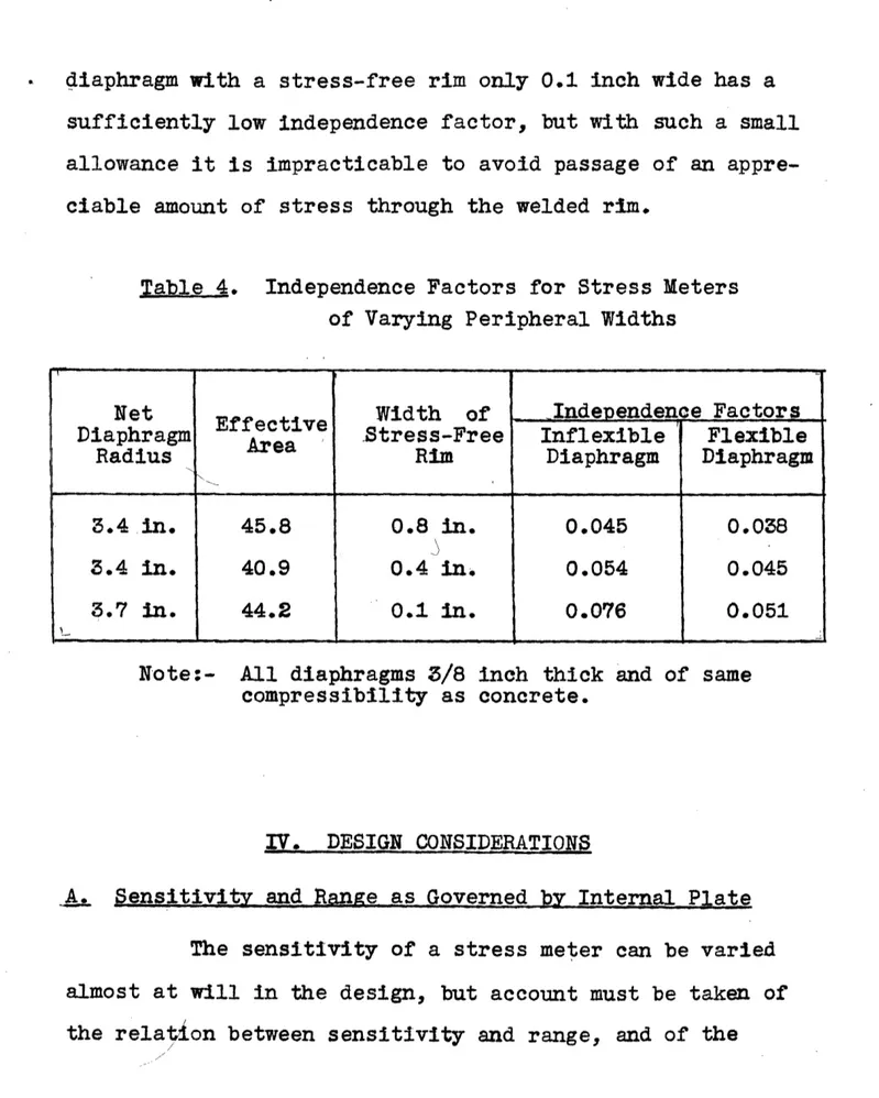
The conditions at the rim of a stress meter dia-phragm have already been mentioned, but they will be recalled before results of analyses are discussed. If the welded rim were left bare when a diaphragm were cast in concrete, an un-known amount of stress would be transmitted directly through the solid-metal rim. In early stress meters, expensive
transfer load from the rim to the mercury film some distance in from the edge. This design was so unsatisfactory that a
simpler design was adopted for which the feature was a fabric-wrapped rim. This wrapping produces a void area as far as stress is concerned, and the stress that would normally fall on this area is shared about equally by the diaphragm and surrounding concrete; only a small stress escapes around the metal rim. This makes the effective area of the diaphragm
somewhat greater than the net area in contact with concrete, and tests indicate that to include half of the rim area with the diaphragm is approximately correct.
C. Results- of Analyses
It is recalled again that no analyses are necess-ary for the simple case when a stress meter tends to con-tract under load exactly as much as the surrounding concrete. The stress meter must then indicate the true compressive
stress, provided the calibration is accurate. Analyses are necessay only for the purpose of determining the extent of
error when concrete and diaphragm tend to compress unequally. In Fig. 6 are shown the conditions which result when a stress meter tends to contract by a different amount
from the surrounding concrete. Because, as previously ex-plained, only the effect of a difference in desired deforma-tion need be analyzed, the diaphragm is assumed to have no
F-0 z qjq a -Z Qj `* ,* s), o... '' ,
4'i
--- - - __-r-_ - - __: -( ) ... . . I I ' 1a I M - _ 187000(3/~ inch) Midplane O didaphagmQUARTER SECTION BEFORE CONTRACT/ON
(6REATLY EXAGGERATED VERr1CAL SCALE)
Dl_ A _I
j
rneA atterroni -o, . ' j. <d =) *d i9i
. .' _'_ _. : ·- -."", .. a ...'. ".'- :'.!'; D ; O .-·-A o.~ A- ~',, :~, ~,--: 4 *. a ':: - .aj M* r... ~treury I - ~I I 4_ -O O 0 U L0 0 tfj - _---- . -187000OU/ARTER SECTION AFTER CONTRACTION
i
Compression ondioaphragm, ave. 7 8 p.s.i.
4 from
3 Z
Cetner of D/aphragm, inches
5TRES55E5 CAUSED
BY CONTRACTION
Fig.6
Effect
of
Con+raction of Concrete on
Flexible
Diaphraqm with
O.
8
-in. Rim
D . 'if 'V '* . ... ~n `C 4 ._P Q 0C :.Z: ich Tension n concrete Dis ftnce S - zs 'F O 50 _, O lll rnlrll r~rrrl~.ln Irrm ·· l··rrr· Irr~rr... n~nll ... --
--,---l~lllllll~lIll T1Trrrrll ~ r~rrlriln7 1711 111 rl1lT1l1l I~~~~~~~~~~~~~~~~~~~~~~~~~~~~~~~~~~~~~~~~~~~~~~~~~~~~~~
I `I I · -
--I
desired deformation, while the concrete contracts by a nomi-nal 100 millionths of an inch per inch. The results in Fig. 6 are for a stress-meter diaphragm which is completely flexi-b:le. The upper two diagrams are quarter sections of a stress-meter diaphragm (strain-stress-meter unit omitted) before and after the contraction of the concrete. The vertical scale is
greatly enlarged so as to show the deformations; for this reason the section has been cut to confine attention mainly to the boundary of the diaphragm that is in contact with the concrete. The space marked void" represents the wrapped rim, which cannot accept stress from the concrete.
A comparison of the two uppermost diagrams in Fig. 6 shows that the concrete upon contracting has "warpedw around the stress-meter diaphragm and has bent it without having com-pressed it noticeably. The third diagram, near the bottom of Fig. 6, shows the forces which are consistent with the defor-mations.. No credence should be given to the apparent distinuity of the stress distribution in the surrounding con-crete, as the method of analysis necessitates the assumption of' uniform stress on each ring of finite width. The more re-fined the analysis, the closer the stress distribution would approach a smooth curve. The stress over the face of the phragm is necessa*rily uniform in this case, because the dia-phragm is assumed to be flexible and it contains a fluid film.
It may be noted that the compressive stress on the diaphragm is only 7.8 p.s.i., whereas if the diaphragm had been com-pressed to the full extent of the concrete contraction, the stress would have been 200 p.s.i. (E = 2,000,000 p.s.i.). Thus, the independence factor is 0.039 (= 7.8/200), in ac-cordance with the definition previously stated. The total compressive stress on the diaphragm is exactly balanced by tension in the surrounding concrete as is required by the conditions of the analysis.
In Fig. 7 are the graphical results of an analysis for an inflexible diaphragm. In this case the compressive :stress on the diaphragm need not be uniform, but the dia-phragm must remain substantially plane. The variation from planeness reflects the inexact nature of the analysis. Again,
the diaphragm is compressed by only a fractional amount of
the concrete contraction. The average stress on the diaphragm
am5ounts to 9.0 p.s.i., which may be compared again with the 200 p.s.i. corresponding to full contraction of the concrete. The independence factor in this case is 0.045. Comparing the latter factor with the factor of 0.039 as found above for a flexible diaphragm, it may be seen that the difference is not great. For practical purposes, the average of the two
fac-tors is considered to be sufficiently accurate for an actual stress meter, whose diaphragm is somewhat flexible.
CM/idp/ane of diaohragm
QUARTER
SEC TON BEFORE CONTRA CTIOAPlaneA f/er conrfac lon 'i.~ o~~~~~ 4 ", .' .,
,
~. ' " ','' · 4 '7 ·444 : 0-..' ''4 ..', 4 ,.. 6 ' - '. ' 0 ... ' ,` /.:.. o'.'.-.'~-: .: ." * 4 .;64 :· q . 4-,a: 4·' 4,.. 1:. '-:-9!~:,.~. -~~ ."; VQUARTER SECT/ON AFTER CONTRA CT/ON
... .. ,.."..ill i III
Tension in. concrete
50 f Compression on diaphragm 5 (Ave 9.0 p.s .) I_
IJ
l~
''`H~
H[
~`~'`~````~``'`'H`H``"` ~ 'H~ ~IIH 0
[~~
'"~"~
5 4 3 2 0D/s'fance from Cenfer of Diaphragm, inches
5TR£55E5 CAUSED BY CONTRACT/ON
Fig.7
Effect
of Contraction of Concrete on
Inflexible Diaphragm with
.8-in. Rim
I
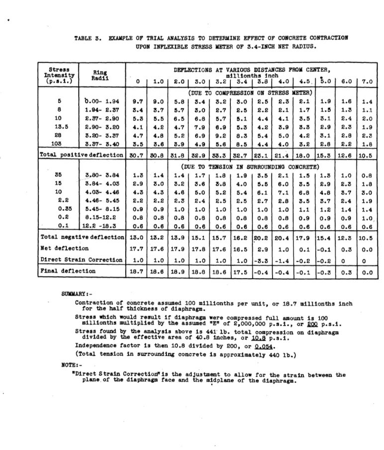
IV .3 4Q., o.. I-4. zo uu 20ki 870Q0 -i -IZ ,6 (3/te /;nch) ,:nch) vA 'I 4. rI ti I I LA sample computation sheet is presented as Table 3 to show the origin of such results as are included in Figs, 6 and 7. The data in Table 3 comprise one final trial to determine the stress distribution on and around a particular stress meter due to a contraction of the crete, according to the method explained above. The con-crete is assumed to contract 100 millionths of an inch per inch while the diaphragm tends to remain at fixed thickness. The final stresses must be such that the entire area of the diaphragm in contact with the concrete is deflected rela-tively to the currounding concrete by 100 millionths of an
inch per inch, or 18.7 millionths in the half thickness of the diaphragm. The data can best be visualized by assuming as a first step that a plane is cut through the concrete and the diaphragm midway between the two faces of the diaphragm.
After the concrete contraction, the diaphragm will extend
out 18.7 millionths of an inch from the plane of the
con-crete, because in the cut condition there can be no compres-sion on the diaphragm. The stresses shown in Table 3 are such as to deflect the diaphragm back into the plane of the concrete and yet to maintain the concrete plane and to leave no unbalanced forces. The deflections are actually reckoned from the plane of the diaphragm face instead of the midplane and the additional deflections in the half