HAL Id: tel-01725368
https://tel.archives-ouvertes.fr/tel-01725368
Submitted on 7 Mar 2018HAL is a multi-disciplinary open access
archive for the deposit and dissemination of sci-entific research documents, whether they are pub-lished or not. The documents may come from teaching and research institutions in France or abroad, or from public or private research centers.
L’archive ouverte pluridisciplinaire HAL, est destinée au dépôt et à la diffusion de documents scientifiques de niveau recherche, publiés ou non, émanant des établissements d’enseignement et de recherche français ou étrangers, des laboratoires publics ou privés.
multiphase polymer systems
Joao Paulo Cosas Fernandes
To cite this version:
Joao Paulo Cosas Fernandes. Co-localized AFM/Raman characterization of multiphase polymer sys-tems. Polymers. Université Grenoble Alpes, 2017. English. �NNT : 2017GREAI081�. �tel-01725368�
THÈSE
Pour obtenir le grade de
DOCTEUR DE LA COMMUNAUTE UNIVERSITE
GRENOBLE ALPES
Spécialité : Matériaux, Mécanique, Génie Civil, Électrochimie
Arrêté ministériel : 25 mai 2016
Présentée par
João Paulo COSAS FERNANDES
Thèse dirigée par Laurent GONON etcodirigée par Vincent MAREAU
préparée au sein du Laboratoire Systèmes Moléculaires et
nanoMatériaux pour l'Energie et la Santé / Polymères Conducteurs Ioniques
dans l'École Doctorale Ingénierie-Matériaux, Mécanique
Énergétique, Environnement, Procédés, Production (I-MEP²)
Co-localisation AFM/Raman :
Caractérisation de systèmes
polymères multiphasés
Thèse soutenue publiquement le 16 novembre 2017, devant le jury composé de :
DR Didier R. LONG
Directeur adjoint Laboratoire Polymères et Matériaux Avancés LPMA de Lyon (UMR5268), CNRS – Président
Pr. Isabelle ROYAUD
Département Science et Ingénierie des Matériaux et Métallurgie (SI2M) de l’Institut Jean Lamour (UMR 7198), Université de Lorraine - Rapporteur
Pr. Odile FICHET
Co-directrice du Laboratoire de Physicochimie des Polymères et des Interfaces (EA2528), Université de Cergy Pontoise - Rapporteur
DR Deborah JONES
Directrice associée de l’Institut Charles Gerhardt de Montpellier, CNRS - Membre
Co-localized AFM/Raman
characterization of multiphase
polymer systems
João Paulo Cosas Fernandes
This dissertation is submitted for the degree of Doctor of Philosophy
16 November 2017
Even Diamonds start as Coal
Just give it Time
The Fire feels Divine
- Incubus
Acknowledgements
First I would like to thank my thesis directors Laurent Gonon and Vincent Mareau,
for believing in me and giving me the means to fulfill my goals, inside the lab and outside
as well. Laurent was always pushing me to go beyond the expectations, always scientifically
rigorous and critical, but also a good listener to my ideas and opinions. Vincent is a master
of experimentation in the lab, with whom I learned a lot about putting ideas into practice.
Our scientific discussions have always been a challenge for me, but also made me go
further into any subject we worked on together. I hope the best for you !
To my friends from the lab, Ph.D. students, post-docs, senior researchers, professors,
staff... You were part of my daily life for the past 3 years and I thank you a lot for the good
times we spent together. Lucille, Katya, Natacha, Nicolas, Coraline, Tao, Rémi, Laurent,
Christopher, thank you for the daily laughs and for the great support until the very end !
Hakima, you are a great person, mother and researcher. You have always been there for me
when I needed answers, with your enthusiasm and kindness. Emilie, Charly and Joëlle,
thanks for being my support in the daily life of the lab, from experiments to the
bureaucracy of a foreign student, you were always very helpful and kind. Jojo, may you
continue to enlighten peoples’ life with your great sense of humor !
Outside the lab, I had the pleasure of meeting incredible people, each of one battling
to achieve their best selves. I thank the people that kindly welcomed me back in Grenoble,
Figueira, Julianny, Drieli and Marina, and all the BRAFITECs that came into my life and
made it more joyful. Volta, Lorena, Ebert, Contin, Raíssa, Juliana, Luciane, Thibault.. Thanks
for the shared moments. I thank the CrazyVosDent volleyball team for the two and a half
years of partnership, victories, defeats and apéros after each match. Les Ducs du Tranqui !
Certainly the best friends I had the pleasure of meeting and living together for the past 2
years. Tuxo and Xaxa, thanks for the good moments, discussions, laughs, travels and
snowboarding weekends. I am truly grateful for the daily support and I hope the best for
your future ! A special thanks to Julie Grande, for being by my side until the end, for caring
for my back’s health and for teaching me more than she can imagine.
I thank my family, my aunts, uncles and cousins, for the support you gave me at
each step of my education and for the warmest welcomes each time I come back home.
At last, but not least, I thank my parents Sonia and Mauricio. You have always been
there for me, you gave me all the conditions and opportunities to be who I am today. Even
when my decisions made me go so far away from home, you gave me strength. For you
both, I will keep trying my best. I love you.
Contents
INTRODUCTION xiii
CHAPTER 1 MOTIVATION
PROLOGUE 1
1. Heterogeneous and multi-phase complex polymer materials 2
1.1. Polymer Blends 2
1.2. Multilayer Polymeric Materials 3
1.3. Fiber Reinforced Polymer Composites 6
1.3.1. Polymer Nanocomposites 8
1.4. Block-copolymers 10
2. Bulk vs Surface Properties 11
2.1. Characterization of both the Surface and Bulk of Polymer Materials 13
2.2. Sample Preparation Techniques for Bulk Direct Observations 14
3. Polymer membranes 15
4. Manuscript Structure 16
CHAPTER 2
Co-Localized AFM/Raman and Complementary Analyses
PROLOGUE 19
1. Fundamentals of Atomic Force Microscopy 20
1.1. Fundamentals of PeakForce Quantitative NanoMechanics (QNM) 21
1.2. System Calibration for Quantitative Nano-Mechanical Measurements 24
1.3. Nanomechanical Models for Quantitative Measurements 25
1.4. Absolute vs Relative Calibration Method 27
2. Fundamentals of Raman Spectroscopy 28
2.1. Raman Principle 28
2.2. Raman Mapping and Spatial Resolution 29
3. AFM-Confocal Raman Coupling 32
3.1. Commercially available AFM-Raman coupling systems 32
4. Sample Preparation Techniques 35
4.1. Cryo-Fracture 35
4.3. Focused Ion Beam (FIB) cross-sectioning 39
4.4. Summary Table of Sample Preparation Techniques 41
5. Complementary Analyses 43
5.1. Optical Microscopy (OM) 43
5.2. Electron Microscopies 43
5.2.1. Scanning Electron Microscopy (SEM) 44
5.2.2. Transmission and Scanning Transmission Electron Microscopy (TEM/STEM) 47
5.3. Fourier Transform Infrared Spectroscopy (FTIR) 49
5.4. Summary Table of Characterization Techniques 51
6. Conclusions of Chapter 2 53
6.1. Difficulties related to sample preparation by Cryo-Ultramicrotomy 53 6.2. Difficulties related to the co-localization of AFM/Raman analyses 53
7. Conclusions du Chapitre 2 en Français 54
7.1. Difficultés liées à la préparation des échantillons par Cryo-Ultramicrotomie 54 7.2. Difficultés liées à la co-localisation des analyses AFM/Raman 54 CHAPTER 3
Experimental Methods and Developments
PROLOGUE 57
1. Sample preparation by Cryo-Ultramicrotomy 57
1.1. Sectioning of injection molded specimens 58
1.2. Sectioning of polymer membranes 59
1.3. Cryo-ultramicrotomy parameters 59
1.4. Avoiding frost melting water-diffusion onto the sample’s surface 60
2. AFM/Raman Co-localization Setup 60
2.1. Atomic Force Microscope (AFM) 61
2.1.1. AFM Calibration Method 61
2.2. Raman Spectrometer 67
2.2.1. Raman Calibration Method 67
3. Co-localization Methods 68
3.1. Co-localization with the Co-localized Raman Microscope 68
3.2. Co-localization with the Regular Raman Microscope - Shuttle Stage 69
4. Complementary Analyses 71
4.3. µ-ATR-FTIR imaging 71
5. Conclusions of Chapter 3 73
6. Conclusions du Chapitre 3 en Français 74
CHAPTER 4
Compatibilization of Polymer Blends based on PA6/ABS
PROLOGUE 77
1. Theoretical Background and Motivation 78
1.1. Polyamide 6 (PA6) 78
1.2. Acrylonitrile-Butadiene-Styrene (ABS) 79
1.3. Mixing and compatibilization of polymer blends 80
1.4. Objectives of work 81
2. Study of compatibilization of PA6/ABS blends with SAN-MA 82
2.1. Materials used 82
2.2. Blending protocols 82
2.3. Phase identification of the reference sample by Raman and AFM analyses 83
2.4. Effect of blending protocol on morphology 85
2.5. Effect of the morphology on the rheological behavior 87
2.5.1. Discussions of the effect of blending protocol on morphology and rheological
properties 88
2.6. Effect of SAN-MA compatibilizer on PA6 structure 89
2.6.1. PA6 polymorphs quantification by Differential Scanning Calorimetry (DSC ) 90 2.6.2. Distribution of PA6 polymorphs studied by co-localized AFM-Raman analyses 91 2.6.3. Discussions of the effect of SAN-MA compatibilizer on PA6 structure 94
3. Conclusions of Chapter 4 95
3.1. Summary of conclusions of Chapter 4 96
4. Conclusions du Chapitre 4 en Français 97
4.1. Résumé des conclusions du Chapitre 4 en Français 98
CHAPTER 5
Hybrid Membranes for Fuel Cell
PROLOGUE 101
1. Theoretical Background and Motivation 102
1.1. Hydrogen Fuel Cells Fundamentals 102
1.2. Polymer Membrane Electrolytes 103
1.3. Sol-Gel method 105
1.4. Objectives of work 106
2. Study of hybrid membranes based on dimethoxysilane (SHDi) precursors 107
2.1. Materials used 107
2.2. Micro-scale distribution of the SG along the membrane’s cross-section 108 2.3. Impact of the processing steps on the hybrid membrane’s morphology 110 2.4. Impact of the processing steps on the hybrid membrane’s nanomechanical properties and
SG uptake 112
2.5. Insights on the SG condensation process thanks to the water trapped at the
ultramicrotomed surfaces 112
2.6. Morphological evolution over time 114
2.7. Nano-manipulation and nanomechanical characterization of growing crystals 115
2.7.1. Co-localized AFM/Raman analysis on the crystals 116
2.8. Morphological Analysis by Scanning Electron Microscopy (SEM) 117 2.9. Discussion of the characterization of hybrid membranes based on SHDi precursor 118 2.10. Complementary µ-ATR-FTIR analysis – Feasibility and preliminary results 120 2.11. Conclusions of the Study of Hybrid membranes based on SHDi precursor 122 3. Study of hybrid membranes based on trimethoxysilane (SHTriM) precursors 123
3.1. Materials used 123
3.2. Effect of the thermal treatments on the membrane’s morphology 124
3.2.1. Effect of the SG uptake on the morphology 125
3.3. Complementarity between AFM and SANS 126
3.3.1. Fundamentals of Small Angle Neutron Scattering 126
3.3.2. SANS experiments 127
3.4. Co-localized AFM/Raman cross-section analysis 129
3.5. Conclusions of the Study of Hybrid Membranes based on SHTriM precursors 131
4. Summary of Conclusions of Chapter 5 132
5. Résumé des Conclusions du Chapitre 5 en Français 134
CHAPTER 6
Copolymer Electrolytes for Lithium Batteries
PROLOGUE 137
1. Theoretical Background and Motivation 138
1.1. Lithium Batteries Fundamentals 138
1.4. Morphological Analysis of Polymer Electrolytes 142
1.5. Objectives of work 143
2. Study PS-PEO-PS copolymers doped with lithium salt 144
2.1. Materials used 144
2.2. Sample preparation for cross-section analysis 145
2.3. Morphological study of PS-PEO-PS copolymers 146
2.3.1. Effect of the Lithium salt on the morphology 146
2.4. Effect of reticulation on PS-PCi-PS copolymers morphologies 150
3. Study of “single ion” copolymer electrolyte 152
3.1. Material used 152
3.2. Morphology of PSTFSILi-PEO-PSTFSILi copolymer 153
3.3. Surface morphology and properties evolution with hydration degree 156
4. Conclusions of Chapter 6 161
4.1. Summary of Conclusions of Chapter 6 162
5. Conclusions du Chapitre 6 en Français 163
5.1. Résumé des Conclusions du Chapitre 6 en Français 164
CONCLUSIONS 166
ANNEXES 186
Annex 1. Annexes of Chapter 4: Compatibilization of compatibilized blends based on PA6/ABS 187
Annex 1.1 Blending procedure 187
Annex 1.2 Raman band assignment of the blend components 187
Annex 1.3 Rheological Measurements 189
Annex 1.4 Differential Scanning Calorimetry (DSC) 189
Annex 1.5 Fabrication and analysis of the reference PA6 polymorphs 189 Annex 1.6 Co-localized AFM-Raman analyses of the compatibilized blends 191 Annex 1.7 Raman analysis of characteristic PA6 γ-phase band at 960 cm-1 193
Annex 2. Annexes of Chapter 5: Hybrid Membranes for Fuel Cell 193
Annex 2.1 Fabrication process of the hybrid membranes based on SHDi precursor 193 Annex 2.2 Thermogravimetric Analysis (TGA) of hybrid membranes based on SHDi precursors 194 Annex 2.3 Raman assignment of the sPEEK and SG phase chemical signatures 194 Annex 2.4 Fabrication process of the hybrid membranes based on SHTriM precursor 196
Annex 2.5 Effect of trapped water on the surface of Polyethylene terephthalate (PET)
membranes 196
List of Tables 201
List of Figures 202
Abbreviations
ABS
Acrylonitrile-Butadiene-Styrene.
ATRAttenuated Total Reflection.
ATR-FTIRAttenuated
Total
Reflection
Fourier
Transform Infrared Spectroscopy.
BSE
Backscattered Electrons.
DDeflection.
DMADynamic Mechanical Analysis.
DSCDifferential Scanning Calorimetry.
EModulus.
EDSEnergy Dispersive X-ray Spectroscopy.
EELSElectron Energy Loss Spectroscopy.
EOCEthylene Octene Copolymer.
EPDMEthylene Propylene Diene Terpolymer.
FForce.
FIBFocused Ion Beam.
FT-IRFourier transform Infrared Spectroscopy.
G’Storage Modulus.
GFGlass Fiber.
GFcnon-treated commercial glass fiber.
GFfGlass Fiber with film former.
HDPE-g-MAHPolyethylene-graft-Maleic Anhydride.
HTHydroThermal.
iPPisotactic Polypropylene.
IRInfrared Spectroscopy.
kSpring Constant.
LBLithium Batteries.
LDPELow Density Polyethylene.
LEPMILaboratoire d’Electrochimie et de
Physico-chimie des Matériaux et des Interfaces. ,
LiTFSILithium bis(trifluorosulfone)imide.
LMPLithium Metal Polymer.
MAMaleic Anhydride.
MEAMembrane Electrode Assembly.
MMA-MAMethyl Methacrylate-Maleic Anhydride.
MPPMaleic anhydride grafted Polypropylene.
ɳ*
Complex Viscosity
NRNatural Rubber.
OMOptical Microscopy
OsO4Osmium tetroxide
PA6Polyamide 6
PBPolybutadiene.
PCPolycarbonate.
Post-condensation.
PCLPoly-ε-caprolactone.
PEMFCProton Exchange Membrane Fuel Cells.
PEMWEProton
Exchange
Membrane
Water
Electrolyzer.
PEOPolyethylene Oxide.
PETPLA
Polylactic acid.
PLLAPoly(L-lactic acid).
PMMAPoly(methyl methacrylate).
POEPolyolefin Elastomer.
PPPolypropylene.
PSPolystyrene.
PSTFSILiPolystyrene-grafted-Lithium
bis(trifluorosulfone)imide.
QNMQuantitative NanoMechanics.
RTip radius
R-PA6Recycled-Polyamide 6.
RuO4Ruthenium tetroxide.
s. SAN-MAStyrene-Acrylonitrile grafted with Maleic
Anhydride.
SANS
Small Angle Neutron Scattering.
SAXSSmall Angle X-Ray Scattering.
SBCStyrene-Butadiene Copolymer.
SESecondary Electrons.
SEMScanning Electron Microscopy.
SGSol-Gel.
SHDi(3-mercaptopropyl)-methyldimethoxysilane.
SHTriM(3-mercaptopropyl)-trimethoxysilane.
sPEEKsulfonated Polyether-etherketone. ,
SPEsSolid Polymer Electrolytes.
STEMScanning
Transmission
Electron
Microscope.
TEMTransmission Electron Microscope.
Transmission Electron Microscopy.
TgGlass Transition Temperature.
TGAThermogravimetric Analysis.
TmMelting Temperature
UFSCarFederal University of São Carlos.
UHMWPEUltrahigh Molecular Weight Polyethylene
VDeflection Voltage
WAXDWide Angle X-Ray Diffraction.
WVPWater Vapor Permeability
XANESX-ray Absorption Near Edge Structure.
XPSX-ray Photoelectron Spectroscopy.
ZZ-Position
δIndentation
υPoisson ratio
INTRODUCTION
In this thesis, we present the development of an innovative approach for the characterization of polymer systems, especially membranes, that couples co-localized Atomic Force Microscopy (AFM) and Confocal Raman microspectroscopy with electron microscopies (STEM and SEM) and other complementary techniques. We present here an experimental approach giving access to topographic, nanomechanical and chemical co-localized analyses after cross-sectioning of polymer membranes using cryo-ultramicrotomy without epoxy embedding. Obtaining co-localized information is the key element to study the process-structure-properties relationship of a variety of heterogeneous or multiphase polymer systems, like blends, nanocomposites, hybrids, multilayers and aged materials. The project was carried out in the Laboratory of Molecular Systems and Nanomaterials for Energy and Health (SyMMES), under the guidance of Laurent Gonon and Vincent Mareau.
Our objective was to develop an experimental methodology of characterization capable of providing multiples information at multiple scales, analyzing a single sample specially prepared to be suitable for complementary analyses. A substantial effort was done in order to apply this strategy to the characterization of thin polymer membranes (thickness below 100 µm). We demonstrated that the co-localization of information is essential for the elucidation of the process-structure-properties interplays, for various systems like compatibilized polymeric blends, hybrid polymer membranes for Fuel Cell, and also copolymer electrolyte membranes for lithium batteries.
French Introduction
Dans cette thèse, nous présentons le développement d'une approche innovante pour la caractérisation des systèmes polymères, en particulier des membranes, qui couple la Microscopie de Force Atomique (AFM) avec la microspectroscopie confocale Raman avec des microscopes électroniques (STEM et SEM) et d'autres techniques complémentaires. Nous présentons ici une approche expérimentale donnant accès à des analyses topographiques, mécaniques et chimiques co-localisées après coupe transversale des membranes polymères à l'aide de cryo-ultramicrotomie sans enrobage d'époxy. L'obtention d'informations co-localisées est l'élément clé dans l'étude de la relation structure-structure-structure d'une variété de systèmes polymères hétérogènes ou polyphasés, tels que des mélanges, des nanocomposites, des hybrides, des multicouches et des matériaux vieillis. Le projet a été réalisé dans le laboratoire des Systèmes Moléculaires et des nanoMatériaux pour l'Energie et la Santé (SyMMES) sous la direction de Laurent Gonon et Vincent Mareau.
Notre objectif était de développer une méthodologie de caractérisation expérimentale capable de fournir des multiples informations sur plusieurs échelles, en analysant un échantillon unique spécialement préparé pour être adapté aux analyses complémentaires. Des efforts considérables ont été faits pour appliquer cette stratégie à la caractérisation de membranes polymères fines (épaisseur inférieure à 100 μm). Nous avons démontré que la co-localisation de l'information est essentielle pour l'élucidation des interactions mise en œuvre-structure-propriété, pour divers systèmes tels que les mélanges de polymères compatibilisés, les membranes polymères hybrides pour les piles à combustible et les membranes polymères pour les batteries au litthium.
CHAPTER 1
MOTIVATION
PROLOGUE
This chapter will illustrate the complexity of different polymeric systems, such as polymer blends, multilayers, (nano)-composites and copolymers. For each system, we will present studies where the understanding of their intrinsic complex characteristics and interactions was important and challenging for the development of new engineering solutions. We will see, among other examples, how the morphology of immiscible polymer blends affects their mechanical properties, and how their performances can be optimized; the effect of a compatibilization strategy on the performance of polymer composites reinforced with glass fibers and its effect on the matrix morphology, and finally the importance of the control of copolymer morphologies or crystalline polymorphs on the functional properties of gas separation membranes.
The last part of this chapter will be focusing on the necessity to characterize both the surface and the bulk of materials. For the sake of clarity, we will consider the term “bulk” as being a synonym of “core”, i.e., relative to the interior of the volume or thickness of the material, excluding the external surface. We will show that the proper characterization of the whole material (bulk + surface) makes possible the understanding of degradation processes or the optimization of material properties by tuning both bulk and surface morphologies and chemistries. Finally, a particular attention will be given to thin polymeric materials like films and membranes, for which additional technical challenges are associated to achieve co-localized information, and to separate bulk and surface contributions.
French Prologue
Ce chapitre illustrera la complexité des différents systèmes polymères, tels que les mélanges de polymères, les multicouches, les (nano)-composites et les copolymères. Pour chaque système, nous présenterons des études où la compréhension de leurs caractéristiques et interactions complexes intrinsèques était importante et difficile pour le développement de nouvelles solutions d'ingénierie. Nous verrons, entre autres exemples, comment la morphologie des mélanges de polymères immiscibles affecte leurs propriétés mécaniques et leur performance optimale; l'effet d'une stratégie de compatibilité sur la performance des composites polymères renforcés avec des fibres de verre et leurs effets sur la morphologie de la matrice, et enfin l'importance du contrôle des morphologies du copolymère ou des polymorphes cristallins sur les propriétés fonctionnelles des membranes de séparation des gaz.
La dernière partie de ce chapitre sera axée sur la nécessité de caractériser à la fois la surface et l’intérieur des matériaux. Par souci de clarté, nous considérerons le terme «masse» comme synonyme de «noyau», c'est-à-dire par rapport à l'intérieur du volume ou de l'épaisseur du matériau, à l'exclusion de la surface externe. Nous montrerons que la caractérisation appropriée de tout le matériau (masse + surface) permet de comprendre le processus de dégradation ou l'optimisation des propriétés du matériau en accordant à la fois les morphologies et les chimies de masse et de surface. Enfin, l'attention particulière sera accordée aux matériaux polymères minces comme les films et les membranes, pour lesquels des défis techniques supplémentaires sont associés à la acquisition d'informations co-localisées et à séparer les contributions de la masse et de la surface.
1. Heterogeneous and multi-phase complex polymer materials
1.1. Polymer Blends
A polymer blend is a mixture of two or more polymers to create a new material with specific physical properties.1 This strategy is widely used since the development of a polymer blend is less
time and money consuming than the synthesis of a new polymer for a specific application. However, it requires a systematic study of the process-structure-properties relationships of the blend material. Polymer blends are a typical example of how important the developed morphology is for the final properties of the material. For entropic reasons, most polymers are immiscible2 and the blends show
a phase-segregated morphology, as illustrated in Figure 1.1. The properties of these phases separated materials are roughly the average of the properties of each component alone. For example, Ruckdäschel et al.3,4 have studied immiscible poly(2,6-dimethyl-1,4-phenylene ether) (PPE) and
poly(styrene-co-acrylonitrile) (SAN) blends. SAN is a rather rigid material with a modulus of 3.80 ± 0.12 GPa, presenting low deformation at rupture and fracture energy (2.93 ± 0.06 % and 27 ± 1 kJ/m2). Compared to SAN, PPE presents a lower modulus of 2.50 ± 0.09 GPa but much higher
deformation at rupture of 69.8 ± 39 % and fracture energy (710 ± 443 kJ/m2). The authors have
shown, for example, that for a 60/40 composition (wt%), a PPE/SAN blend verifies the rule of averaged properties: a modulus of 3.08 ± 0.15 GPa, a deformation at rupture and fracture energy of 40.2 ± 24.5 % and 418 ± 252 kJ/m2 respectively. Transmission Electron Microscopy (TEM) image on
Figure 1.1 shows the continuous nature of the SAN (bright phase) while the PPE (dark phase) tends to form particles. The proper control of the morphology, considering size and distribution of the domains, interface interactions and adhesion between the components, is mandatory to obtain improved synergic properties.
Material
E (GPa)
ε
(%)
W (kJ/m
2)
PPE
2.50 ± 0.09 69.8 ± 39.0 710 ± 443
PPE/SAN 60/40 3.08 ± 0.15 40.2 ± 24.5 418 ± 252
SAN
3.80 ± 0.12 2.93 ± 0.06
27 ± 1
Figure 1.1. TEM micrograph of an immiscible PPE/SAN 60/40 wt% blend and table of mechanical properties of PPE, SAN and 60/40 PPE/SAN blend.3,4
Improvement of modulus is only attained on polymer blends when the adhesion of the materials at the interfaces is sufficient. If not the case, the incompatibility between the components can lead to the formation of defects at the interface and therefore to brittle characteristics.3 One of
the most mature strategies to improve the miscibility of polymer blends is compatibilization. Compatibilizing agents are chemically modified copolymers capable of interacting with one or both components of the blend, acting like surfactants to modify the interfacial tension between phases, improving the phases’ dispersion. The final morphology developed in the presence of these compatibilizers corresponds to smaller droplets of the minority phase dispersed into the main component. Ruckdäschel et al.3,4 have used this strategy to improve the miscibility of PPE/SAN
PPE/SAN blend with the increasing amount of SBM and the mechanical properties of each composition. They observed that the addition of 5 wt% of SBM led to no significant morphological change, but almost doubled the deformation at rupture and the fracture energy (from 40.2 ± 24.5 % to 76.4 ± 14.6% and from 418 ± 252 kJ/m2 to 817 ± 156 kJ/m2, respectively). These improvements were
attributed to the presence of the compatibilizer at the interphase, confirmed by TEM by the irregularly contrasted regions at the phases’ boundaries (Figure 1.2 (b)). Increasing SBM compatibilizer’s ratio up to 10%, the morphology of the blend was modified, becoming co-continuous, which improved the deformation at rupture and the fracture energy of the blend up to 97.9 ± 3.0% and 1022 ± 32 kJ/m2 respectively. On the other hand, the Young’s modulus keep on
dropping from 3.08 ± 0.09 GPa for the uncompatibilized blend to 3.01 ± 0.09 GPa for 5% SBM and 2.84 ± 0.07 GPa for 10% SBM. Further addition of SBM to 20 wt% turned back the morphology to a dispersed PPE phase into a SAN matrix. However, the average droplet size of the PPE phase was reduced in comparison to the previous compositions. The good deformation at rupture and the fracture energy properties were maintained (96.8 ± 12.7% and 944 ± 127 kJ/m2) but it caused a more
pronounced drop of the modulus (2.57 ± 0.06 GPa).3,4 This example evidences the need to understand
the impact of the compatibilizer on both the morphology and the mechanical properties of the compatibilized blends in order to optimize their resulting properties
Material E (GPa) ε (%) W (kJ/m2) PPE/SAN 60/40 3.08 ± 0.15 40.2 ± 24.5 418 ± 252 +5 wt% SBM 3.01 ± 0.09 76.4 ± 14.6 817 ± 156 +10 wt% SBM 2.84 ± 0.07 97.9 ± 3.0 1022 ± 32 +20 wt% SBM 2.57 ± 0.06 96.8 ± 12.7 944 ± 127
Figure 1.2. TEM micrographs showing different morphologies developed for increasing amount of SBM compatibilizer into PPE/SAN blends. The table presents the corresponding mechanical properties. 3,4
1.2. Multilayer Polymeric Materials
Another approach used to combine properties of different polymers in a material is to produce multilayer films, with each layer consisting of a polymer with specific properties. These materials are widely used in the food industry. To guarantee the integrity and safety of the food, packaging films must have the following properties: strength (resistance to puncture, impact and tear), sealing and preservation against moisture (barrier to the transmission of water vapor in or out), oxygen (to reduce microbial activity), light (prevent light-induced changes in flavor or nutritional quality) and chemicals (prevent the food from absorbing unwanted substances from the environment). The use of a single material with all those properties is highly improbable. Hence the development of multilayer materials is of prime importance.5,6 Figure 1.3 shows an example of
multilayer material which is mainly composed of an outer layer of Nylon, responsible for the mechanical strength and scuff resistance, a layer of Ethylene vinyl alcohol (EVOH), which is an excellent gas barrier, and a layer of Low Density Polyethylene (LDPE), an inert polymer good for
food-contact. In order to ensure that the layers stick to each other, an adhesive layer called “tie layer” is often used.
Figure 1.3. Example of multilayer polymer material composed of an outer layer of nylon, a gas barrier layer of EVOH and the contact layer of LDPE intercalated with adhesive layers
Multilayer processing creates interfaces between different materials and the adhesion between them is critical for the mechanical and barrier properties. To overcome this problem, it was necessary to develop adhesives layers, or “tie layers”, which are used between each different polymeric layer to enhance surface compatibility and to seal up any voids and defects. Common adhesives used on multilayers are based on reactive polyurethane chemistry, i.e, the reaction of an isocyanate with a hydroxyl group to form a urethane linkage. The isocyanate pre-polymer will always contain a portion of free diisocyanate monomer, which is consumed within the adhesive layer during the curing reaction. The major issue of this adhesive layer consists on the migration of unreacted diisocyanate through the layers into the food, in which it can react with water, forming amines. Some aromatic amines are potential carcinogens, thus, it is very important to study the nature of the materials used as adhesives and the efficiency of the curing process, in order to ensure the safety of the material for food application.5–9 However these investigations are challenging due
to the complexity of the final product and the low thickness of each phase.
For some other applications, the ability of selected additives to migrate through the layers can also be used to improve the multilayer properties. For example, Gherardi and coworkers7
developed a procedure to incorporate antimicrobial agents in a multilayer material, based on a commercial packaging with a polyurethane adhesive free of isocyanate. They have studied the antimicrobial activity of the new films and the release of the active compounds. Mass spectrometric results showed that the compounds were released from the adhesive layer, crossing the material and reaching the food for antimicrobial action. On the other hand, the researchers claimed that a deeper research was necessary to study the correlation between their release rates and the thickness, chemical composition and structure of the adhesive layer. The characterization of the chemical profile throughout the cross-section of the multilayer film, for example with spectroscopy techniques, could have given insights on the specific layer limiting or controlling the release rate of the antimicrobial agents. The challenge for this kind of sample is to be able to properly open the membrane, if possible without an embedding, to avoid a chemical contamination of the material by diffusion of the embedding medium.
The gas barrier properties, often required for multilayer polymer materials (not only for food packaging), will depend on the nature of the gas and the properties of the polymers, such as the
Gas Barrier layer
Product contact layer
low leachable levels
Outer layer
Strenght and scuff resistances
barrier properties are highly affected by crystallization and orientation of the lamellae, as the chains packing affects the free volume available for gas transportation.10–15 Cocca and coworkers16 have
studied the effect of crystal polymorphism on the mechanical and barrier properties of Poly(L-lactic acid) (PLLA). They have shown how the degree of crystallinity (crystal fraction) and the nature of the polymorph (α or α’) affected the Young’s modulus and elongation at break (Figure 1.4(a) and (b), respectively). The authors discussed how the transition from the α’ to the α polymorph (higher chain packing and interchain interaction for the α form) affected the mechanical properties of the material, improving Young’ modulus but decreasing elongation at rupture. This transition from α’ to α form corresponds also to the abrupt decrease of the water vapor permeability (WVP), shown on Figure 1.4(d), with somehow the same degree of crystallinity (very small increase of the crystal fraction). Correlation between optical microscopy and Wide Angle X-Ray Diffraction (WAXD) analysis was used to estimate the polymorphic composition of the PLLA samples, however, no quantitative determination was possible due to the very similar WAXD profiles of the two polymorphs.16 This problem could be addressed by the co-localization of microscopies and
spectroscopy techniques, which could have provided direct morphological and chemical information for the quantitative analysis of the nature of the phases in the samples.17 Furthermore, the analysis
of the distribution of polymorphs and the size of the crystallite in the samples could have explained the drop on the elongation at break and WVP for samples with almost the same degree of crystallinity (Figure 1.4 (c)).
(a) (b) (c)
Figure 1.4. Different properties of PLLA films as function of the degree of crystallinity: (a) Young's modulus, (b) elongation at break and (c) permeability to water vapor (WVP). The crystal polymorphs are indicated for each degree of crystallinity.16
1.3. Fiber Reinforced Polymer Composites
A composite is a structured material that consists of two or more constituents which are combined at a macroscopic level and are not soluble in each other.18The matrix of the composite,
generally continuous, can be a metal, a ceramic, carbon or a polymer. Embedded inside the matrix, the second constituent is the reinforcing phase, which can be of different natures (ceramic clays, polymers/ natural fibers, inorganic fillers...) and have a variety of forms and shapes, such as fibers, particles or flakes. The nature and shape of the secondary phase is mainly determined by the application or the properties that one wants to improve.
The most common use of the polymer composite strategy is for the enhancement of mechanical properties of the polymer itself. For this mean, fibers are generally used due to their high aspect ratio, i.e., the ratio between their length and diameter (l/d). The performance of a polymer/fiber composite will be determined by the interactions between the matrix and the reinforcement. Indeed, the mechanical properties of the composite are mainly ensured by the fibers and a good charge transfer from the matrix to the fibers is necessary to reach the best performances. This load transfer is only effective if the fibers are well dispersed in the matrix and if the adhesion of the matrix on the fiber is good. Therefore the quality of the interface can be problematic when hydrophobic polymer matrices like Polyethylene are used with hydrophilic fibers like glass fibers for example. The incompatibility between the components leads to poor wettability during processing, creating discontinuities and voids at the interface, which are ineffective for load transfer and actually act like stress-concentration points, hampering the mechanical performance of the composite.
In order to improve and guarantee the interface bonding, a common strategy is based on the chemical modification of the fiber’s surface using a sizing to improve their wettability by the matrix, and the creation of chemical bonds between the fiber’s surface and the polymer matrix. For example, a sizing containing a coupling agent is commonly applied on glass fibers. The most common kind of coupling agents used are organometallic or organosilanes.19–23 Organosilane
precursors are molecules that contain two types of reactive functional groups (Figure 1.5): one capable of forming chemical bonds with inorganic materials and one capable of interacting with organic materials. The hydrolysis of the ethoxy or methoxy groups (O-X) in contact with water leads to the formation of silanol groups, which engender the creation of oligomers by partial condensation. The silanol dimers hydrogen bond to the surface of the fiber and then, through water condensation, chemical bonds are created between the coupling agent and the surface of the glass fibers. The reactive group R bore by the coupling agent (vinyl groups, epoxy, amino, mercapto, etc) is available to physico-chemical interactions with the chain of the polymer matrix, improving wettability, miscibility and forming chemical bonds or hydrogen bonds with polar matrices.
Other alternatives to the use of silane coupling agents have been developed with the use of reactive copolymers like Maleic Anhydride grafted on polyolefines.24–26 For example, Guojun Luo et
al 24 studied a polypropylene/glass fiber (PP/GF) composites prepared by treating GF with a film
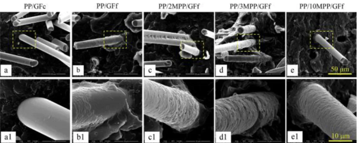
former (GFf) containing maleic anhydride grafted polypropylene (MPP) and a β-nucleating agent. The interfacial adhesion and the crystal morphology between GF and PP were observed by scanning electron microscopy (SEM) (shown on Figure 1.6) and the tensile and impact strength were measured (Table 1.1). The composite prepared with the non-treated commercial fiber (GFc) presented poor interfacial adhesion and a smooth GF surface was observed after debonding (Figure 1.6 (a)). This caused poor mechanical properties, i.e., no substantial improvement on tensile strength (from 27.1 MPa for PP alone to 31.3 MPa for the composite) and especially the impact strength, which dropped from 10.4 to 5.1 kJ/m2, as shown on Table 1.1. The interfacial adhesion was improved
by the presence of the coating film. SEM images showed a layer of remnant polymer on the surface of the GFf after debonding (Figure 1.6(b)) and the tensile strength attained 61.8 MPa. With the addition of 2 wt% MPP, the covering polymer layer on the GF surface appeared thicker and with a roughen fracture surface. The fact that the impact strength attained 14.2 kJ/m2 (roughly the double
from the composite without MPP) evidenced the better adhesion interface. The authors verified that when the content of MPP was increased to 3 wt% and 10 wt%, the interface microstructures appeared nearly identical, with fibers completely covered (Figure 1.6 (c), (d) and (e)). On the other hand, the tensile strength of the composites increased from 61.6 MPa (3 wt% MPP) to 67.3MPa (10 wt% MPP), even though the interface microstructure was unchanged.
Figure 1.6. SEM micrographs representing the interfacial adhesion between GF and PP matrix for PP/GFc (a, a1), PP/GFf (b, b1), PP/2MPP/GFf (c, c1), PP/3MPP/GFf (d, d1) PP/10MPP/GFf (e, e1). (a1), (b1), (c1), (d1) and (e1) are enlarged areas marked by the dashed yellow squares in (a), (b), (c), (d) and (e) respectively. 24
Table 1.1. Tensile and Impact strength of the PP composites 24
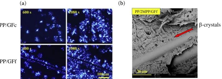
To understand the impact of the GF coating film on the crystallization process, the researchers monitored the isothermal crystallization by optical microscopy. On the one side, for PP/GFc sample, PP crystals nucleated randomly and grew into large spherulites, as shown on Figure
1.7(a). On the other side, in PP/GFf sample, nuclei were found concentrated near the surface of GFf, and after 600 s a layer of oriented crystalline lamellae was found surrounding the GFf. A SEM image of the etched fractured surface of this sample showed structures in the form of spikes grown perpendicular to the fibers, which were attributed to β-transcrystals. The very good adhesion of these crystals to the GFf surface (intimate contact between the two materials) is thus suspected to be responsible for the efficient stress transfer between the PP matrix and the GF. Structural, chemical and morphological analyses of these structures (by Confocal Raman for example) could have provided an unambiguous attribution of the crystals nature. In addition, nano-mechanical properties, such as adhesion and modulus profiles at the fiber-matrix interface could have been accessed by AFM in order to characterize the quality, integrity and continuity of the interface.
(a)
(b)
Figure 1.7. (a) Polarized optical micrographs during an isothermal PP crystallization at 135°C around a single fiber (GFc or GFf) (b) SEM micrograph of the etched fracture surface for PP/2%MPP/GFf injection molded sample. Adapted from 24
The impact of the coupling agent at the fiber-polymer interface has to be studied at a local scale to be able to optimize the material’s performances. Therefore the development of characterization methods that can provide direct probing of morphological, mechanical and chemical properties of the polymer-fiber interface/interphase could accelerate the progress in the field.
1.3.1. Polymer Nanocomposites
The complexity of composite materials increases when one of the fillers has at least one of its dimensions in the nano-range, turning it into a nanocomposite material. Usually nanocomposite materials have enhanced properties when compared to their non-nano composite equivalent.27–33
Inorganic additives, like calcium carbonate, glass beads, talc and clay for example, were often used as fillers on polymer materials to reduce cost and enhance the mechanical properties, but the use of the corresponding nano-fillers has given them a much more functional interest.
As for the reinforcement fibers, the interface between the nanoclay and the polymer is determinant in the effectiveness of load transfer from the polymer matrix to nanofillers. As most polymers are hydrophobic, they are not compatible with hydrophilic nanoclays for example. This means that a simple mixing of the components would create agglomerates of nanoclay, which would lose their nano-dimensions. An exfoliation of the nanoclay and their perfect embedding by
β-crystals
PP/GFc
agglomerated and an exfoliated nanocomposite.29 The exfoliation and uniform dispersion of
nanofillers in the polymer matrix can be achieved by means of surface modification of clays, like grafting and chemical treatments, solution induced intercalation process, in situ polymerization and melting process.27,29,34–37 Pramoda and coworkers38 studied how the mechanical and thermal
properties of polyamide 6/clay nanocomposite are influenced by the exfoliation degree of the clay particles. They suggest that exfoliated nanocomposites exhibit higher onset temperature for degradation than those with agglomerated clay particles. Chan et al.30 have used morphological
characterization to tune their fabrication process in order to produce uniformly-dispersed samples. Thanks to the better dispersion, even when small amounts of nanoparticles from 1 to 10 wt% were incorporated in the polymer matrix, a substantial improvement of mechanical properties was achieved, e.g., up to 57% increase in Young’s Modulus using 7 wt% of nanoclay inside an epoxy matrix. Improvements were also observed for exfoliated nanocomposites on their barrier properties, chemical resistance, reduced solvent uptake and flame retardancy: the exfoliated nanofillers making the diffusion pathway through the nanocomposite much more intricate.36,39–44 Therefore
nanocomposites require lower amounts of fillers than regular composites to reach comparable performances.29
(a)
(b)
Figure 1.8. SEM image characteristic of nanoclay morphology in a 95/5 wt% Polyamide6-Montmorillonite nanocomposite: (a) agglomerated and (b) exfoliated.29
Inorganic nanoparticles can also have an impact on the crystallization of the polymer matrix by acting as heterogeneous nucleation sites. Smith and Vasanthan45 have studied the effect of
nanoclay on the crystallization kinetics and spherulitic morphology of poly(trimethylene terephthalate) (PTT)/nanoclay films. They have shown by polarized light microscopy (PLM) that the addition of 10 wt% of nanoclay had great impact on the size and distribution of the spherulites, as shown on Figure 1.9. The conformational changes induced were monitored by Infrared spectroscopy, indicating that nanoclay accelerates the polymer chain conformational transition from trans to gauche. Differences on crystallinity and/or on the crystal structure (polymorphism) have been shown to greatly impact the mechanical and thermal properties of composites.45–51 The
association of optical microscopy with spectroscopy techniques could have directly provided not only information about the conformational transition but also the distribution of the different polymorphic crystals induced by the presence of the clay, by probing the chemical structure of each crystal seen on the optical image.
(a)
(b)
Figure 1.9. PLM photographs of (a) neat PTT and (b) PTT nanocomposite with 10wt% of clay. Adapted from45
1.4. Block-copolymers
Block-copolymers, contrary to polymer blends, present covalent links between different polymeric materials usually immiscible, which gives very specific properties due to the resulting nanophase separation (self-assembly). The challenge on the development of these materials lies on the precise control of the nanostructure morphology. This can be achieved by tuning the molecular weight, monomer chemistry and processing temperatures, for example. When composed by two immiscible blocks, nanodomains dimensions can range from 5 nm to more than 100 nm, and the developed morphology can exhibit a big variety of symmetries, resulting into, for example, lamellae, cylinders, bicontinuous gyroids and even body-centered cubic arrays of spheres, as illustrated on Figure 1.10.52–54
(a) (b) (c) (d)
Lamellae Hexagonal packed cylinders
Bicontinuous gyroids Cubic packed spheres Figure 1.10. Example of copolymer morphologies: (a) lamellae (b) hexagonal packed cylinders (c)
bicontinuous gyroids and (d) cubic packed spheres. Adapted from 52–54
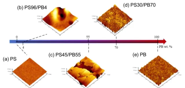
A good example of the impact of the copolymer morphology on its properties is given by Zhuang et al.55 who studied for styrene-butadiene copolymer (SBC) membranes the impact of the
polystyrene/polybutadiene (PS/PB) ratios on both the gas separation (CO2/N2) performance and the
ageing properties. They have detected different nanophase-separated structures by AFM at the surface of the copolymer membranes depending on the PS/PB ratios as illustrated on Figure 1.11. Three different morphologies were obtained: cubic lattice spheres of PB in a continuous PS matrix (4 wt% PB), PS and PB lamellae parallel to the membrane surface (55 wt% PB) and cylinders of PS in a continuous PB matrix (70 wt% PB). Crystalline regions inside the PS domain were observed in both
structure of the PS domain. According to the authors, the synergism between the lamellar morphology and the presence of α crystals in the PS phase increased the diffusion pathway for CO2
and simultaneously enhanced the CO2/N2 selectivity. A similar result was obtained for the
cylindrical structure, which presented γ crystals in the PS phase. The different spacing within the crystal lattice restricts the N2 transport but do not significantly affect the CO2 permeability. This
leads to an even higher CO2/N2 selectivity for the PS30/PB70 membrane. Furthermore, the
researchers have shown that the cylindrical micro-structure of the PS30/PB70 membrane exhibited high ageing resistance under operation conditions, due to the morphological stability of the cylindrical micro-structure. The authors prepared these membranes by spin-coating, leading to a membrane thickness of about 10 µm. For such thickness, the morphological analysis of the surface by AFM might be insufficient for the correlation of properties with the morphology, i.e., the development of the morphology through the membrane thickness may be considerably different from what observed at the surface. A cross-section analysis (after cryo-ultramicrotomy for example) would therefore be appropriate to get a deeper understanding of the obtained morphologies. In addition, co-localized confocal Raman spectroscopy may offer a mapping of the PS α/γ crystals distribution and ageing effects on the bulk of the membranes.
Figure 1.11. AFM topographic images on the membrane’s surface of (a) PS, (b) PS96/PB4, (c) PS45/PB55, (d) PS30/PB70 and (e) PB. Adapted from 55
2. Bulk vs Surface Properties
As discussed on the previous sections, the properties of polymeric materials depend on their nanostructure, the proper control of phase separation, the dispersion and distribution of charges and the quality of interfaces, all of these parameters being potentially variable through the material thickness. The resulting heterogeneities of properties can be induced by the processing methods, or tailored intentionally to achieve specific distinct properties for the surface and the bulk. In addition, after ageing, materials become generally heterogeneous in terms of chemistry, morphology and mechanical properties, due to the inhomogeneous degradation process through the material (surface/bulk).
Processing of thermoplastic polymers is mainly related to the application of shear to the molten material at high temperature followed by high thermomechanical stresses due to the rapid cooling of the material at the end of the process. Therefore, the thermomechanical history may not
be homogeneous throughout the whole thickness of the material, inducing differences in the local order of the polymer chains and the distribution of additives. This can result in different morphologies in terms of molecular orientation, lamellar thickness, crystal structure, shape and dimensions, crystallinity degree, orientation of the amorphous phase, dispersion state of a blended polymer, length and orientation of reinforcing fibers and crystalline texture (skin-bulk structure), since the kinetics and morphology of crystallization are intrinsically related to the flow and cooling regimes.56 In injection molding, for example, the surface morphology is highly affected by the
thermomechanical stresses induced by the rapid cooling of the chains when in contact with the cold mold and the orientation of the chains caused by shear stress. Liparoti and coworkers57 performed a
multiscale mechanical characterization of isotactic polypropylene (iPP) injection molded samples. The developed morphologies were characterized by polarized optical microscopy and AFM, as shown on Figure 1.12.
They revealed a complex multilayer morphology composed of globular elements, fibrils and spherulites, from the surface to the bulk of the sample. The thickness of the different layers was correlated to the injection molding conditions (packing pressures and mold temperatures). The authors also evidenced a correlation between the local mechanical properties and the different morphologies formed along the sample thickness. At the sample’s surface, the cooling rate is the highest, which does not allow the crystallization of the macromolecules, therefore low modulus is found. Further from the surface, as the cooling rate decreases, the macromolecules can align themselves and, due to the stress induced by the flow, form compact structures characterized by higher moduli in the shear layer. As the bulk of the material takes more time for cooling and is less affected by the shear, the polymer chains have more time to crystallize, forming spherulites. Thus, flow and thermomechanical stresses will cause a gradient of different morphologies from the surface to the bulk.
Figure 1.12. Morphology profile through the material thickness detected by optical microscopy (central micrograph) and by AFM height maps. The positions where the analyses were performed are indicated by arrows pointing on the cross section optical micrograph.57
Important material properties such as optical, chemical, electrical and ionic transport can be tuned by adjusting the material’s morphology or gradient of morphologies. For example, the
liquids, will depend on both the surface and the bulk properties. On the one hand, the selective sorption of molecules on the membrane’s surface is controlled by the morphology, roughness and chemical properties at the surface (hydrophilicity/hydrophobicity, chemical affinity, etc.) and on the other hand, the diffusion of these absorbed molecules through the thickness of the material is controlled by the bulk morphology, dispersion of charges, cross-linking degree, etc.58–63 Wei Zhang
and coworkers63 have studied the pervaporation performance of polymeric chitosan membranes by
simultaneously changing their surface and bulk structures. To adjust the degree of crystallinity of the membrane’s bulk they tuned the pre-drying processing step (the shorter this step the lower the degree of crystallinity of the bulk). A lower crystallinity implied that the transport of the permeation molecules was faster, i.e., a membrane with a less compact structure exhibited a higher flux, however it had a lower separation factor. In order to improve selectivity they functionalized the membrane’s surface with maleic anhydride. After modifying both the bulk and the surface of the membranes the authors improved by 400% the separation factor and by 60% the flux. They concluded that the combination of bulk modification by pre-drying treatments and surface functionalization was an effective method to simultaneously improve both the permeability and permselectivity of polymeric membranes, but they claim that further research needs to be done in order to understand the relationship between the membrane’s bulk characteristics and the pervaporation process. The clear and direct characterization of both the membrane’s bulk and surface remains therefore the main technical challenge to be solved.
Ageing is another source of surface/bulk heterogeneity. It results of complex physical and chemical interactions, such as physical creep and relaxation, chemical degradation by oxidation, chain scission and hydrolysis, induced from the operating conditions: high mechanical stresses, mechanical and thermal cycling, attack by chemical agents or UV light exposition, for example. These complex interactions affect the surface and the bulk of the material in different ways. For example, during the thermal ageing of polymers, the bulk can be affected by structural and morphological changes caused by temperature-induced transitions, while the surface is mainly affected by thermo-oxidative degradation, which is limited to a thin surface layer up to a few tens of micrometers, depending on the kinetic of oxidation of the material. The surface contamination of the material by fuels, lubricants and chemicals can diffuse through the thickness of the material over time. Reciprocally, additives such as plasticizers or stabilizers can migrate from the bulk to the surface of the material over time. These diffusion processes and the chemical reactions involved in the ageing mechanism are affected by the nature of the material (selective sorption of molecules on the surface), the state of order and morphology in polymer blends, multilayers and composites, as well as the nature, size and dispersion of charges, and porosity distribution. Thus, during ageing, a gradient profile is formed inside the material. Therefore, the understanding of the mechanisms and kinetics of diffusion and degradation from the surface to the bulk, and of the effects of morphological and chemical changes on the material properties offer a chance to develop ageing mitigation strategies.64,65
2.1. Characterization of both the Surface and Bulk of Polymer Materials
This section will focus on the experimental techniques classically used for chemical and morphological characterization of both the surface and bulk of polymer materials.
The characterization techniques used for probing the chemical properties of surfaces are based on vibrational spectroscopies and backscattered radiation. The most common vibrational spectroscopies used are Fourier Transform Infrared Spectroscopy (FT-IR) and Raman spectroscopy. These techniques use the frequency-dependent absorption or emission of radiation from chemical bonds and structures, in order to identify and quantify components or chemical groups in the
structure. For IR spectroscopy, Diffuse Reflectance FTIR (DRIFTS) and Specular Reflection FTIR are used for the characterization of rough surfaces (powders) and smooth surfaces, respectively. Attenuated Total Reflection Fourier Transform Infrared Spectroscopy (ATR-FTIR) is the most popular technique for surface analysis due to the short penetration depth (~1 to 5 µm depending on the crystal used and the wavenumber), allowing the characterization of a large area (~1 mm2) of the
top layer of the material. Raman spectroscopy is a complementary technique to IR spectroscopy, because some vibration modes are inactive in IR and active in Raman, and vice-versa, allowing the complete chemical characterization of the material. Energy Dispersive X-ray Spectroscopy (EDS or EDX) is a technique based on the interaction of the material with an electron beam, and is used for identifying, quantifying and mapping elements on the surface of the material. X-ray photoelectron spectroscopy (XPS) has a lateral resolution from 1 mm to 10 µm, but a depth resolution of tens of nanometer, being particularly suitable for elementary analysis of modified surfaces, such as plasma-treated or oxidized surfaces, thin coatings or grafted polymers on the surface.
The characterization of the physical properties of the surface include the morphology, topography, crystallization, microphase separation, as well as size, shape, distribution and orientation of charges which can be analyzed by direct observation, e.g., using optical or electron microscopies.66
Optical Microscopy is a resolution (classical resolution roughly about 0,5-1 µm) and low-magnification technique (from 2x up to ~2000x) used to provide a first look at the surface, due to its easy sample preparation, low cost and simple principles of operation. Scanning Electron Microscopy (SEM) is widely used for the characterization of surfaces with high magnification (up to 500000x) and high resolution (5~10 nm) and can provide additional interesting information depending on the interactions of the electron beam and the specimen used to obtain the image. Using separate detectors for Backscattered Electrons (BSE/ sensitive to electronic density) and Secondary Electrons (SE/ sensitive to surface topography), compositional and topographic images of the same area may be produced. Finally, Atomic Force Microscopy (AFM) is an advanced technique for surface analysis based on the interaction of a scanning probe with the sample’s surface. Three dimensional topographic images are obtained, giving access to morphological measurements, including roughness. The lateral resolution will depend mainly on the tip radius of the probe (typically ~5-10 nm). The substantial developments of the past years have enabled different modes of operation, allowing probing the mechanical, thermal, electrical and magnetic properties of the material’s surface with a high spatial resolution.
The characterization of the bulk properties is usually performed using techniques that probe the material as a whole, averaging the response of the surface and the bulk. For example, Differential Scanning Calorimetry (DSC) and Dynamic Mechanical Analysis (DMA) are used to evaluate the thermomechanical behavior of the material, providing insights on phase transitions, miscibility of components, crystallinity and degree of crosslinking. However in order to do a direct observation and probe the bulk of the material (without surfaces), special techniques are required to open the sample for optical/electron microscopies, AFM imaging (topography, mechanical, etc.) and chemical mapping (Raman, µ-ATR-FTIR), which will be discussed in the next section.
2.2. Sample Preparation Techniques for Bulk Direct Observations
The most used and simple technique to access the bulk of a material is the cryo-fracture, in which the polymer is cooled in liquid nitrogen (-196ºC), in order to induce afterward a brittle fracture in the rigidified material at its glassy state. The sample is then installed or glued to a support and the surface is imaged using a microscope (generally SEM). Although easy to prepare,
unpredictable brittle fracture creates irregular rough surface which can follow the material heterogeneities, like particles or phases with different mechanical properties, making difficult to understand the real morphology of the material. Other advanced techniques used to provide better cross-sections are Cryo-Ultramicrotomy and Focused Ion Beam (FIB). Cryo-ultramicrotomy is based on the use of a diamond knife operating at cryo temperature to cut ultrathin slices (down to 50 nm) of the material’s surface with controlled cutting speed, angle and depth. FIB cross-sectioning uses a high energy (~30 kV) ionic beam, typically gallium, of 10 nm to 1 µm in diameter to cut the sample surface with controlled parameters. Both techniques can provide surfaced samples with very flat surfaces and minimum artifacts for direct observation by Optical Microscopy, Scanning Electron Microscopy (SEM), Atomic Force Microscopy (AFM) and can also provide thin sections (~50 nm) for complementary morphological analysis using Transmission Electron Microscopy (TEM).67–69 An
advanced discussion of these sample preparation techniques will be presented on Chapter 2.
3. Polymer membranes
For polymer films/membranes, the need to distinguish the surface from the bulk of the material becomes even more crucial than it can be for massive polymer products. Indeed the properties gradients that can be found from the surface to the bulk of the membranes can develop at length scales comparable with the membrane’s thickness. A polymer film is a continuous planar material which is flexible and “free-standing”, with thickness ranging from a few hundreds to tenths of micrometers, in opposition to ultrathin films (thickness at nanometer scale) coated on a substrate.70 Polymer films can be made of a single material or multiphase systems (blends,
composites, multilayers) and are commonly used as barriers for separation of two mediums, like in packaging, or electrical insulators for wires and cables. The term membrane is often used to designate polymer films with specific functionalities of technological interest, i.e., it can be considered as an interphase between two mediums acting as a selective barrier, responsible for the regulation of gas transport, diffusion of liquids or ions between each side of the membrane.71 Due to
these functionalities, membranes are widely used for technical applications, such as desalination of water through reverse osmosis, nanofiltration, dialysis, separation of molecules, liquids or gases, and ion exchange electrolytes for fuel cells and electrolyzers. Due to their technological importance, this section will focus on membranes rather than polymer films.
Membranes can be manufactured by a variety of processes, such as extrusion of the polymer melt, hot pressing, polymerization on substrates and casting by solvent evaporation. Each method induces different morphologies (orientation, asymmetries) on the surface and through the thickness of the membrane, which can deeply affect their functional properties. Figure 1.13 represents the different questions of interest on the surface and the bulk of polymer membranes. However, distinguishing the chemical and physical contributions from the surface and the bulk on these low thickness materials can be difficult due to the experimental issues on accessing, probing and differentiating properties and morphologies.