HAL Id: cea-02338602
https://hal-cea.archives-ouvertes.fr/cea-02338602
Submitted on 21 Feb 2020
HAL is a multi-disciplinary open access archive for the deposit and dissemination of sci-entific research documents, whether they are pub-lished or not. The documents may come from teaching and research institutions in France or abroad, or from public or private research centers.
L’archive ouverte pluridisciplinaire HAL, est destinée au dépôt et à la diffusion de documents scientifiques de niveau recherche, publiés ou non, émanant des établissements d’enseignement et de recherche français ou étrangers, des laboratoires publics ou privés.
B. Moudjed, L. Rossi
To cite this version:
B. Moudjed, L. Rossi. Exploration of gas entrainment from surface swirls using the processing of flow visualisation and PIV. LXLASER 2018 - 19th International Symposium on the Application of Laser and Imaging Techniques to Fluid Mechanics, Jul 2018, Lisbonne, Portugal. �cea-02338602�
Exploration of gas entrainment from surface swirls using the processing of flow
visualisation and PIV
B. Moudjed 1, 2, *, L. Rossi 1, 3, *
1: CEA Saclay, DEN, DM2S\STMF\LIEFT, Université Paris-Saclay, F-91191 Gif-sur-Yvette Cedex, France. 2: Applied Mathematics Research Centre, Coventry University, Priority Street, Coventry CV1 5FB, United Kingdom
3: CEA Cadarache, DEN, DTN\STCP\LTHC, 13115 Saint-Paul-lez-Durance, France.
* Correspondent authors: brahim.moudjed@yahoo.fr or ac5206@coventry.ac.uk, lionel.rossi@cea.fr
Keywords: BANGA, gaz entrainment, PIV, image processing, surface swirl ABSTRACT
Surface swirls appear daily in bathrooms and in any liquid container emptied by gravity through a hole. The combination of a free surface shear flow and a downward flow generates a strained two-phase (air and water) spiral vortex looking like to a tornado. These vortices may provoke gas entrainment within the flow. In sodium cooled fast nuclear reactor, gas entrainment studies address fortuitous gas entrainment phenomena from the free surface of the main sodium vessel to the bottom of the reactor. To study gas entrainment and its relation to the generation and intensity of surface swirls an experimental rig (BANGA) amenable to produce intermittent surface swirls and gas entrainment is used. To vary the shear flow responsible for these intermittent phenomena, three reference experiments with different geometrical inlets are performed: i) using a flat plate, ii) and iii) adding half-cylinders at the end of the flat plate with diameters of 12.5mm and 25mm. The inlet Reynolds number varies from 3000 to 25000. Optical measurements such as flow visualisation and PIV are performed to studies these flows. The combination of pictures and PIV processing permit to estimate the gas entrainment, to track the surface swirls and the "source vortex" (single phase vortex before the appearance of the surface swirls within the measurement plan) so as to quantify the local circulation associated to these vortices and the correlation of this local circulation with the gas entrainment. Main results show that the geometrical inlet conditions change the quantity of gas entrained and the longitudinal position of the surface swirls. For similar flow rate conditions, with the presence and the increase of the size of the obstacles: the gas entrainment increases, the surface swirls move in the upstream direction (i.e. closer to the flat plate or obstacle). A first quantification of the circulation along a tracked trajectory combining "source eddy" and surface swirl tracking is given. Current work include the construction of circulation criteria and its correlation to gas entrainment. They should be included in the presentation according to progress.
1 Introduction
Surface swirls appear daily in bathrooms and in any liquid container emptied by gravity through a hole. The combination of a free surface shear flow and a downward flow generates a strained spiral vortex looking like to a tornado. In the case of free surface flows, a strong localized free surface deformation can be observed. Surface swirls are sometimes referred in literature as: "bathtub vortex" (Andersen, Bohr, Stenum, Rasmussen, & Lautrup, 2003), "free surface vortex" (Cristofano, Nobili, & Caruso, 2014; Ezure, Kimura, Hayashi, & Kamide, 2008; Hai-feng, Hong-xun, Zheng, & Yi, 2008), "air-core intake vortex" (Keller, Möller, & Boes, 2014), "air-entraining vortex" (Chang, 1979) (Chang, 1979), "tornado-like vortex" (Vogt, Boden, Andruszkiewicz, Eckert, & Gerbeth, 2015).
The studies of gas entrainment from surface swirls is relevant for different industrial applications. In these cases, their purpose is often to help in the prevention of undesirable effects. In sodium cooled fast nuclear reactor, these studies address fortuitous gas entrainment phenomena from the free surface of the main sodium vessel to the bottom of the reactor, e.g. (Tenchine, Fournier, & Dolias, 2010). In automobile industry, some humidity inside the car can raise from the presence of surface swirls within the water box collecting the rainwater (Kourta, Recoquillon, & Andres, 2015; Recoquillon, Kourta, & Andres, 2011).
Analytical experiments dedicated to the study of gas entrainment from surface swirls mainly rely on two approaches: the use of a maintained surface swirl e.g. (Baum & Cook, 1975; Takahashi, Inoue, & Aritomi, 1988) or the production of intermittent surface swirls, e.g. (Cristofano, Nobili, & Caruso, 2014; Eguchi, et al., 1994; Ezure, Kimura, Hayashi, & Kamide, 2008; Kimura, Ezure, Tobita, & Kamide, 2008).
The experimental rig BANGA (on which are performed the present experiments) is designed to study gas entrainment from intermittent phenomena (Moudjed, Excoffon, Riva, & Rossi, 2016). According to the flow properties, it can provide two types of gas entrainment: i) the gas flows through surface swirl’s core; ii) the gas is transported by bubbles which breakaway from surface swirl tip. In addition to provide new insights about gas entrainment in analytical configurations relevant to Sodium cooled Fast nuclear Reactor, this experimental rig and research intend to provide different test cases for the validation of Multiphase Computational Fluid Dynamic (MCFD) codes, e.g. TRIO-U, TRUST, NEPTUNE-CFD.
Very few experimental studies describe and quantify gas entrainment while measuring the local flow properties and the surface swirls, e.g. (Ezure, Kimura, Hayashi, & Kamide, 2008). The present manuscript aims at quantifying gas entrainment in reference turbulent flows before detailing the underlying turbulent flow structures associated to such gas entrainments.
This work is aimed to quantify the local flow circulation associated to the tracked eddies (and the surface swirls) and to correlate it to the gas entrainment observed. The measurements are obtained from the combination of the tracking of surface swirls (once the air-water interface appears in the measurement plan, using image processing) and of the tracking of "source eddies" (before the appearance of the surface swirl in the measurement plan, using PIV processing).
The first and second parts of this paper describe respectively the experimental rig BANGA, the different measurements and the processing performed. The third part presents some ongoing results and first discussions.
2 Experimental setup
In this work, gas entrainment from surface swirls is characterized by using water experiments. A free surface shear flow is generated in an open channel flow. A suction nozzle is set at the bottom of the test section to induce a downward flow and provoke gas entrainment.
An important originality of these experiments is the possibility to change the inlet condition so as to generate different turbulent shear flows. This is done by adding obstacles of different sizes and shapes at the end of a flat plate separating the inlet flow from a “stagnant” water area (Moudjed, Excoffon, Riva, & Rossi, 2016).
2.1 Experimental rig
Experiments are performed with water within a rectangular open flow channel such as dimensions with the free surface are 700mm length, 108mm width and 210mm height (BANGA experimental set up in CEA Saclay). As depicted in Figure 1, two vertical plates are placed in the middle of the channel so that the inlet and outlet flows are limited to the half of the channel cross-section. These
plates, 300mm apart, allow separating the main free surface flow from a stagnant water area to create a shear flow in the centre part of the channel. A 50mm diameter suction nozzle, noted D, with a height of 100mm, is set at the bottom of the cavity to induce a secondary down-flow by pumping the water under the free surface. The investigated area is the central part of the test section, above the suction nozzle, with dimensions 300 x 108 x 110 mm3. During the experiments,
the temperature of the water is maintained at about 19°C using a cooling device. More details can be found in (Moudjed, Excoffon, Riva, & Rossi, 2016).
Figure 1: BANGA experimental setup: side view at the top and top view at the bottom.
Figure 2: Illustration of a surface swirl occurrence with gas entrainment; bubbles breakaway from the tip of surface swirl. Green line represents horizontal laser sheet at z = 100mm, i.e. 10mm under the free surface.
Coupling the free surface shear flow with the down-flow induces surface swirls occurrences and gas entrainment from the free surface to the bottom of the channel as illustrated in Figure 2. Obstacles of different shapes and sizes can be added on the inlet vertical plane plate to trigger various inlet flow conditions. As the main trends raise from the absence or presence of obstacles and their size (rather than their shape), this manuscript focuses on the cases without obstacles and with half-cylinders of diameters equal to 12.5mm and 25mm.
2.2 Measurements
Gas entrainment mappings are established from direct observations of the different flow configurations (Moudjed, Excoffon, Riva, & Rossi, 2016).
The geometrical properties of surface swirls and the quantity of gas entrained are estimated using shadowgraphy and image processing. Visualizations are performed in white backlighting with a
Stemmer Imaging™ camera to observe surface swirl occurrence and gas entrainment phenomenon. Frames with a spatial resolution of 2048 x 1088 pixels are acquired at 25Hz during 15min. The physical domain observed is 36cm long and 16 cm wide. It includes the free surface and the suction nozzle.
Velocity fields and profiles are measured with the Particle Image Velocimetry (PIV) technique e.g. (Raffel, Willert, & Kompenhans, 1998; Rossi, Doorly, & Kustrin, 2013). A low frame rate and a high frame rate PIV system are used. The low frame rate PIV is used to provide statistics and the inlet conditions corresponding to various geometries and flow rates. The high frame rate PIV system is used to provide real time measurement and the history associated to surface swirls.
For the low frame rate system, PIV measurements are performed using an Evergreen™ laser with double pulse laser sheets (thickness, wavelength, duration and energy: 1mm, 532nm, 5ns, 120mJ). Double frames are recorded using a PowerView™ Plus Charge Coupled Device (CCD) camera of spatial resolution 4872 x 3248 pixels. The time lags of the double frames vary from 1ms to 2.5ms according to the flow rates. PIV computations are performed using Davis™ software from Lavision™. The final correlation windows are square windows of 48 pixels side. An overlap of 50% is applied to build the velocity grid. Typical maximal displacements are about 10 pixels. The final instantaneous velocity fields are smoothed using a 3x3 mobile average.
For the high frame rate system, a continuous laser is used to emit light at 532nm with a maximum power of about 4Watts. The laser sheet is generated in a horizontal plane at z = 100mm, i.e. 10mm under the free surface (see Figure 1and Figure 2), through a homemade optical system (Moudjed, 2013) to reach a thickness smaller than 1mm. The water is seeded with PS Fluored seeding particles from MicroParticles GmbH™ (10μm diameter and 1.51g/cm3 density). Flow visualisations are performed with a PHOTRON™ fast camera. A filter is added on the camera's objective to optically remove the wavelength of the laser. Doing so, the reflection of the laser on the walls and air-water interfaces are quasi-suppressed. Only the fluorescent particles inside the laser sheet are visible on the pictures. According to the inlet and suction conditions, images are acquired in a single frame mode at 500fps or 1000fps. The frame size is of 1280 x 1024 pixels and the spatial resolution is about 9 pixels for 1mm. The PIV computations are performed using Davis™ software from Lavision™. The final correlation windows are square windows of 24 pixels sides. Typical maximal displacements are about 8 pixels. The PIV grid is built with a 50% overlap leading to 107x85 velocity vectors per PIV field. This corresponds to one velocity vector every 1.3mm in the x and y directions.
2.3 Notations
The origin of the Cartesian frame is set on the border of the vertical plate at the height of the suction nozzle: x axis coincides with the horizontal channel flow direction, y and z axis are horizontal and vertical, respectively.
The diameter of the nozzle, D=50mm, is chosen as the reference for the length-scales. Dimensionless coordinates, 𝑥∗ and 𝑦∗, are then defined as:
{𝑥 ∗ = 𝑥−𝑥𝑛𝑜𝑧𝑧𝑙𝑒 𝐷 𝑦∗ =𝑦−𝑦𝑛𝑜𝑧𝑧𝑙𝑒 𝐷 (1)
Relevent mean velocities are the inlet velocities, the suction velocity, and the velocity straight to the obstacle. They are respectively noted 𝑈𝑖𝑛, 𝑉𝑠 and 𝑈𝑜𝑏𝑠. They are defined as:
𝑈𝑖𝑛 = 𝑄𝑖𝑛 𝐿𝑖𝑛ℎ𝑤𝑎𝑡 (2) 𝑉𝑠 = 𝑄𝑠 𝜋𝐷2/4 (3) 𝑈𝑜𝑏𝑠 = 𝑈𝑖𝑛 𝐿𝑖𝑛 𝐿𝑖𝑛−ℎ𝑜𝑏𝑠 (4)
Corresponding Reynolds numbers can then be built as: 𝑅𝑒𝑖𝑛 = 𝑈𝑜𝑏𝑠𝐷 𝜈 (5) 𝑅𝑒𝑠 = 𝑉𝑠𝐷 𝜈 (6)
Following (Moudjed, Excoffon, Riva, & Rossi, 2016), two dimensionless numbers are used to highlight the relative importance of 𝑅𝑒𝑖𝑛 and 𝑅𝑒𝑠.
The dimensionless number κ is used to study phenomena where 𝑅𝑒𝑖𝑛 has a higher impact than 𝑅𝑒𝑆
so that it is expressed as: 𝜅 =𝑅𝑒𝑖𝑛2
𝑅𝑒𝑆
Likewise, the dimensionless number 𝜉 is used to describe phenomena where 𝑅𝑒𝑠 as a stronger
impact than 𝑅𝑒𝑖𝑛. It is defined as:
𝜉 = 𝑅𝑒𝑠2
𝑅𝑒𝑖𝑛 (7)
2.1 Range of flows explored
The range of flows explored is given in Table 1.
Qin m3/h Uin m/s Qs m3/h Vs m/s Res Rein obstacles hobs FP 12.5mm 25mm 1.9 0.05 1.9 0.27 13 500 3 333 5 000 2 500 3.8 0.1 2.8 0.4 20 000 6 667 10 000 5 000 3.2 0.45 22 500 5.7 0.15 3.6 0.5 25 000 10 000 15 000 7 500 4.2 0.6 30 000 4.9 0.7 35 000 7.6 0.2 4.2 0.6 30 000 13 333 20 000 10 000 5.7 0.8 40 000 7.1 1 50 000 9.5 0.25 4.2 0.6 30 000 16 667 25 000 12 500 5.7 0.8 40 000 7.1 1 50 000 Table 1. Main flow parameters
3 Processing performed
3.1 Image processing - estimation of gas entrainment
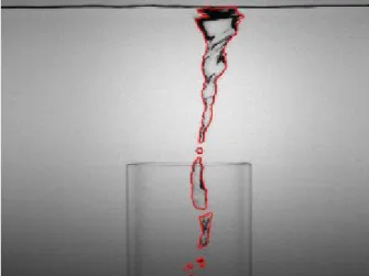
Image processing dedicated to the quantification of surface swirl's geometrical properties and gas entrainment, are performed on frames acquired in xz plane using a shadowgraphy method. An example of obtained pictures is provided in Figure 2. To measure the surface swirls, the air-water interface is identified as a polygon. This is performed using successive steps of image processing: subtraction of the background, detection of edges, binarisation, dilatation, filling, erosion, extraction of the contours as polygons. The Figure 3 gives an example of the identified polygons
superposed to the raw image. This illustration highlights that the surface swirls and issued bubbles are separately identified by this processing. More details about the image processing can be found in (Moudjed & Rossi, 2018).
Figure 3: Illustration of the polygon identification. The polygon (in red) is superposed to the raw picture in grey.
The quantification of the distribution of the air phase within the flow as polygons permits the extraction of the 2D projected positions and areas of these air pockets.
These areas are counted over a measurement domain starting from the bottom of the suction nozzle with a depth depending on the flow speed (within the nozzle) to ensure that all the bubbles are counted and that they are counted only once. More details can be found in (Moudjed, Excoffon, Riva, & Rossi, 2016).
The dimensionless areas is constructed as 𝐴𝑔𝑎𝑠⁄𝐷2 where 𝐴𝑔𝑎𝑠 is the projected area of the gas
entrained and 𝐷 the diameter of the suction pipe. If the threshold for gas entrainment is similar for the small obstacles and the flat plate configurations (Moudjed, Excoffon, Riva, & Rossi, 2016), the estimated quantities of entrained areas and the empirical scaling laws differ between the different configurations.
3.2 Tracking approach
To seek the origin of gas entrainment, a new combination of technical tools (image processing and flow features extracted from PIV) is developed to track and study the surface swirls and the associated “source vortices”.
The tracking method relies on the combination of both image and velocity field processing. The two methods are initialised at the time when the surface swirl appears on high speed PIV frames. This time is noted t0. From t0, the image are processed to identify the surface swirl until the time
TSS when it disappears. The surface swirl is then tracked forward in time. From t0, the velocity
field is processed to identify the source vortex that is tracked backward in time until the time -TSV.
The properties of the source vortex and the surface swirl can then be studied along their trajectories. Figure 4 summarises the temporal organisation of the identification and tracking processes for the surface swirls and the source vortices.
Figure 4: Schematic of surface swirls and source vortex tracking
The detection of the contour of the surface swirl on high-speed PIV frames is performed using image processing. The absence of fluorescent particles within the air phase combined with the optical filtering of the laser wavelength make the air core of the surface swirls identifiable as black areas within the PIV images. Successive steps of image processing permit the extraction of the surface swirl contour as a polygon: images summations over 11 centred time-steps, binarisation, dilatation, edge identification, filling, erosion, contour identification as a polygon. More details can be found in Moudjed & Rossi 2018. The Figure 5 illustrates the extraction of the surface swirl contour as a polygon that is superposed to the raw picture. It can be noticed that the polygon line is well on the edge of black area delimited by the particles.
Figure 5: Illustration of the extraction of the surface swirl contour as a polygon. The polygon, in red, is superposed to the raw picture in grey.
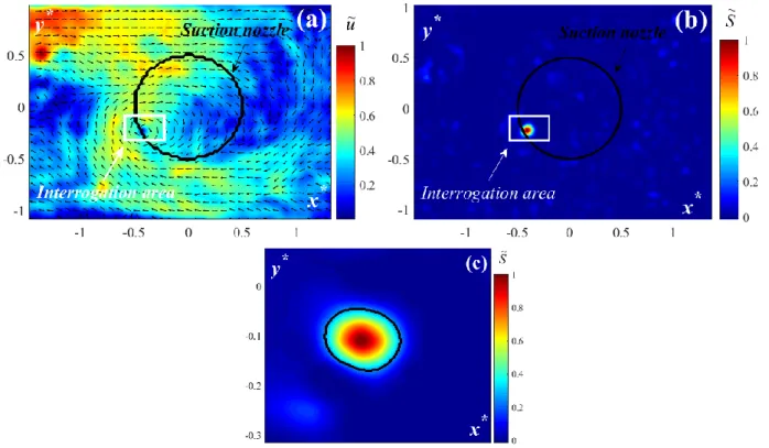
The detection of the eddy (from which the surface swirl is originating) is performed using the 0 level contour of the swirling strength S = −det𝑱 (where 𝐽 = [𝐽𝑖,𝑗] is the Jacobian defined by 𝐽𝑖,𝑗 =
𝜕𝑢𝑖⁄𝜕𝑥𝑗) which is calculated from the PIV velocity fields. Indeed, 2D2C PIV measurements provide a 2D slice of two velocity components within flows. Following Okubo-Weiss decomposition (Okubo, 1970; Weiss, 1991; Ottino, 1989; Haller & Yuan, 2000; Rossi, Doorly, & Kustrin, 2012; Rossi, Doorly, & Kustrin, 2013) the eddy-like structures (whose swirl direction crosses perpendicularly the measurement plan) can be identified according to the sign of the determinant of the velocity Jacobian in the measurement plane, i.e. where S≥0. This is illustrated by figure 6.
Figure 6: Illustration of normalized (a) velocity field and (b) swirling strength in the horizontal plane at z = 100mm, i.e. 1cm under the free surface. Black circle represents the suction nozzle section and white rectangle corresponds to the interrogation area. Normalized swirling strength field inside this interrogation area is plotted in (c) where the
black line is the polygon fitting the iso-contour S0.4.
3.3 Measurement of local flow circulation
Figure 7: Trajectories from the beginning of the vortex source (-TSV) to the disappearance of the surface swirl (TSS) for
the 12.5mm radius half cylinder. Appearance of surface swirl at t0 is indicated with a black round on the total
trajectory. The centre of the suction nozzle is plotted with a black cross. The colour of the plotted trajectory evolves from dark blue colour to dark red.
Figure 7 illustrates a tracked trajectory for the case where a 12.5mm radius half-cylinder is added on the inlet vertical plate with an inlet flow rate of 3.8 m3 h-1 and a suction flow rate of 2.8 m3 h-1.
These vortex and surface swirl identifications combined with their tracking allow to investigate and to quantify the circulation levels associated to the appearance of surface swirls and to the quantity of gas entrained.
The circulation 𝒞 is defined on a circular closed contour ℒ as: 𝒞 = ∮𝒖. 𝑑𝓵
ℒ
,
where 𝒖 is the instantaneous velocity and ℒ a closed contour within the velocity field.
ℒ is chosen as a circle of diameter 0.2D1. During the tracking, ℒ is centred at the centre of the surface
swirl or of the source vortex.
To support the discussion, the dimensionless number 𝒲𝒞 is defined as:
𝒲𝒞=
𝜌𝒞2 0.2𝐷𝜎 ,
with 𝜌 the density of water (𝜌 = 103𝑘𝑔 𝑚3) and 𝜎 the surface tension of water (𝜎 =
73 10−3𝑘𝑔 𝑠−2). 0.2D is about the diameters of the persisting surface swirls.
4 Results and discussion
4.1 Overview of the considered flows
Figure 8 provides surface swirl centre mean positions at 10mm underneath the free surface for flow parameters given in Table 1. Without obstacles (green stars), the centre of the surface swirl is downstream to the suction nozzle centre. Adding an obstacle moves the surface swirl upstream to the suction nozzle centre. Increasing the obstacle's size moves the surface swirl more significantly in the upstream direction.
Figure 8: 𝜅 values versus the dimensionless longitudinal mean position of the surface swirls 𝑥̅̅̅̅. Stars, filled circles, 𝑠𝑠∗
and empty circles respectively represent the flat plate, the 12.5mm half-cylinder and the 25mm half-cylinder.
4.2 Gas entrainment
The quantity of gas entrained is estimated according to the different flow conditions.
Figure 9 gives the entrained gas for the different inlet conditions. The dimensionless areas is constructed as 𝐴𝑔𝑎𝑠⁄𝐷2 where 𝐴𝑔𝑎𝑠 is the projected area of the gas entrained and 𝐷 the diameter
of the suction pipe. If the threshold for gas entrainment is similar for the small obstacles and the flat plate configurations (Moudjed, Excoffon, Riva, & Rossi, 2016), the estimated quantities of entrained areas and the empirical scaling laws differ between the different configurations.
1 The contour diameter 0.2D is close and higher than the maximum surface swirl diameter, and small enough to not include vortex
Figure 9: Dimensionless entrained gas area 𝑨𝒈𝒂𝒔⁄𝑫𝟐 versus . The inlet configurations with 12.5mm and 25mm size
obstacles are respectively plotted with filled and empty symbols. Stars, filled circles, and empty circles respectively represent the flat plate, the 12.5mm half-cylinder and the 25mm half-cylinder.
4.3 Flow circulations
For -TSV and TSS, the measured circulation is about 6m2s-1. Below such value, no surface swirl
is observed. At its maxima, during the appearance of the surface swirl, the circulation is about 10m2s-1. This corresponds to an increase of more than 50% of the circulation during the appearance
of the surface swirl.
Figure 10: Illustration of the measured dimensionless circulation 𝒲𝒞 along a tracked trajectory
On Figure 10, the surface swirl appear for 𝒲𝒞 about 0.8 (which is not far from one). More
detailed quantification of the circulations values and thresholds and their correlation to gas entrainment are part of the work in progress. The authors hope to include new in-progress results in the conference presentation.
5 Conclusion
A work dealing with processing of flow visualisations and PIV measurement is presented. It is performed on two-phase flow involving surface swirl occurrences and gas entrainment. A shear flow is created in a free surface channel and is combined with a downward flow to induce surface swirl and gas entrainment. In the present study, inlet conditions are changed adding 12,5mm and 25mm radius half cylinders on a vertical flat plate.
Firstly, image processing is applied on frames acquired by shadowgraphy. The air/water interface is detected and is associated to a polygon. This allows measuring the geometrical properties of the surface swirl and estimating the quantity (projected area) of entrained air. In particular, these results show that adding obstacles moves the surface swirl upstream and increase the total air entrained through the suction nozzle.
Secondly, high frame rate PIV measurements are performed in a horizontal plane situated at 10mm below the free surface. Since surface swirl appears as a black area on PIV pictures, its contour can be detected and identified to a circular polygon so that it is tracked in terms of centre coordinates and radius. Before the appearance of the surface swirl in the measurement plan, the tracking can be performed using the estimation of a swirling strength function from the PIV measurements. First illustrations of a measured trajectory and of the circulation associated to these source eddy and surface swirl are given.
The work in progress includes, the quantification of tracked eddies and the role of the circulation for the generation of surface swirl and gas entrainment. The authors hope to add such in-progress results to the conference presentation.
Acknowledgments
This work is supported by the R4G program. The authors would like also to acknowledge Jacques Excoffon, Murielle Marchand, Roland Riva CEA colleagues, for their involvement in the development of the experimental set up BANGA and Jean-Paul Garandet, former head of the LIEFT, for his continuous support during this project.
References:
Andersen, A., Bohr, T., Stenum, B., Rasmussen, J., & Lautrup, B. (2003). Anatomy of a Bathtub Vortex. Phys. Rev.
Lett., 91(10), 104502.
Baum, M., & Cook, M. (1975). Gas entrainment at the free surface of a liquid: entrainment inception at a vortex with an unstable gas core. Nuclear Engineering and Design, 32, 239-245.
Canny, J. (1986). A Computational Approach to Edge Detection. IEEE Trans. Pattern Anal. Mach. Intell. PAMI-8, 679-698.
Chang, E. (1979). Scaling laws for air entraining vortices. Hannover: bhra fluid engineering.
Cristofano, L., Nobili, M., & Caruso, G. (2014). Experimental study on unstable free surface vortices and gas entrainment onset conditions. Experimental Thermal and Fluid Science, 52, 221-229.
Eguchi, Y., Yamamoto, K., Funada, T., Tanaka, N., Moriya, S., Tanimoto, K., . . . Maekawa, I. (1994). Gas entrainment in the IHX vessel of top-entry loop-type LMFBR. Nuclear Engineering and Design, 146, 373-381.
Ezure, T., Kimura, N., Hayashi, K., & Kamide, H. (2008). Transient Behavior of Gas Entrainment Caused by Surface Vortex. Heat Transfer Engineering, 29(8), 659-666.
Hai-feng, L., Hong-xun, C., Zheng, M., & Yi, Z. (2008). Experimental and numerical investigation of free surface vortex. Journal of Hydrodynamics, 20(4), 485-491.
Haller, G., & Yuan, G. (2000). Lagrangian coherent structures and mixing in two-dimensional turbulence. Physica D,
147, 352-370.
Keller, J., Möller, G., & Boes, R. (2014). PIV measurements of air-core intake vortices.
FlowMeasurementandInstrumentation, 40, 74-81.
Kimura, N., Ezure, T., Tobita, A., & Kamide, H. (2008). Experimental Study on Gas Entrainment at Free Surface in Reactor Vessel of a Compact Sodium-Cooled Fast Reactor. Journal of Nuclear Science and Technology,
45(10), 1053-1062.
Kourta, A., Recoquillon, Y., & Andres, E. (2015). Control of the intensity of a bathtub vortex by acting on the upstream flow. Mechanics and Industry, 16, 605.
Moudjed, B., & Rossi, L. (2018). processing tools to track and to characterise surface swirls. J. Flow Visual. Image
Proces. (to appear).
Moudjed, B., Excoffon, J., Riva, R., & Rossi, L. (2016). Experimental study of gas entrainment from surface swirl.
Nucl. Eng. Des., 310, 351-362.
Okubo, A. (1970). Horizontal dispersion of floatable particles in the vicinity of velocity singularities such as convergences. Deep-Sea Research, 17, 445-454.
Ottino, J. M. (1989). The Kinematics of Mixing: Stretching, Chaos, and Transport. Cambridge: Cambridge University Press.
Raffel, M., Willert, C., & Kompenhans, J. (1998). Particle Image Velocimetry, a practical guide. Springer.
Recoquillon, Y., Kourta, A., & Andres, E. (2011). Analyse des écoulements diphasiques dans la boîte à eau d’un véhicule automobile. Mecanique Ind., 12, 169-173.
Rossi, L., Doorly, D., & Kustrin, D. (2012). Lamination and mixing in three fundamental flow sequences driven by electromagnetic body forces. Phys. Rev. E, 86, 026313.
Rossi, L., Doorly, D., & Kustrin, D. (2013). Lamination, stretching, and mixing in cat's eyes flip sequences with varying periods. Phys. Fluids, 25, 073604.
Takahashi, M., Inoue, A., & Aritomi, M. (1988). Gas Entrainment at Free Surface of Liquid, (I) Gas Entrainment Mechanism and Rate. Journal of Nuclear Science and Technology, 25(2), 131-142.
Tenchine, D., Fournier, C., & Dolias, Y. (2010). gas entrainment issues in sodium cooled fast reactors. Nucl. Eng. des.,
240, 1195-1217.
Vogt, T., Boden, S., Andruszkiewicz, A., Eckert, K., & Gerbeth, G. (2015). Detection of gas entrainment into liquid metals. Nuclear Engineering and Design, 294, 16-23.