DATA MODELING IN A PAVEMENT MANAGEMENT SYSTEM
By
Wai-Kei Yim
Bachelor of Engineering (with Honors) in Civil Engineering The University of Warwick, July 2000
SUBMITTED TO THE DEPARTMENT OF CIVIL AND ENVIRONMENTAL
ENGINEERING IN PARTIAL FULFILLMENT OF THE REQUIREMENTS FOR THE
DEGREE OF
MASTER OF ENGINEERING IN CIVIL AND ENVIRONMENTAL ENGINEERING
AT THE
MASSACHUSETTS INSTITUTE OF TECHNOLOGY JUNE 2001
© 2001 Wai-Kei Yim. All Rights Reserved The author hereby grants to MIT permission to reproduce
and to distribute publicly paper and electronic copies of this thesis document in whole or in part.
Signature of Author:
Depart t of Civil and Environmental Engineering May 11, 2001 C>11
Certified by:
Senior Lecturer of
George Kocur Civil gnd Environmental Engineering Thesis Supervisor Accepted by:
Oral Buyukozturk Chairman, Departmental Committee on Graduate Studies
MASSACHUSETTS INSTITUTE OF TECHNOLOGY
JUN 0 4 2001
Data Modeling in a Pavement Management System
By
Wai-Kei, Yim
Submitted to the Department of Civil and Environmental Engineering On May 11, 2001 in Partial Fulfillment of the Requirements for the Degree of Master of Engineering in Civil and Environmental Engineering
ABSTRACT
Data modeling is one of the critical steps in the software development process. The use of data becomes a profitable business today and the data itself is a valuable asset of the company. In this thesis, the process of developing a data model will be introduced in the first part. The second part will be a case study. The case study is about the development of the data model of a pavement management system. This is an actual project implemented for the Public Works Department of Arlington, MA.
Thesis Supervisor: Dr. George Kocur
Content
Page Title Page Abstract Content 4-5 Figure List 6 Acknowledgement 7 1 Introduction 82 Data Modeling Theory, Process and Background 10
2.1 The Development of Relational Database and Data
Modeling 10
2.1.1 Flat Files 10
2.1.2 Database Management Systems 11
2.1.3 Hierarchical Model 11
2.1.4 Network Model 12
2.1.5 Relational Theory 13
2.1.6 Standard Query Language (SQL) 15
2.1.7 Conclusion 16
2.2 Data Modeling 18
2.2.1 Business Rules Expression 18
2.2.2 Entity Relationship Approach 19
2.2.3 Data Modeling Phases 20
2.3 Process of Data Modeling 23
2.3.1 Model Types 23
2.3.3
Key Based Model (KBM)
29
2.3.4
Fully Attributed Model (FAM)
34
2.3.5
Business Rules Implementation
39
2.3.6
Normalization
43
2.3.7
Conclusion
47
2.4
Data Modeling in Practice
48
2.4.1
Data Model in Real World
48
2.4.2
Data Model Quality
49
3
M.Eng Information Technology: Arlington Project
52
3.1
Project Background
52
3.2
Data Modeling Requirements
55
3.2.1
Street Data
56
3.2.2
Pavement Analysis
56
3.3
Case Study of Data Modeling
61
3.3.1
Street Data Model
61
3.3.2
Pavement Analysis Model
68
3.3.3
Pavement Condition Model
72
3.3.4
Pavement Management System Model
75
4
Conclusion
79
References
80
Appendix:
Figure List
Page
la Summary data for the Arlington database 9
2.3.2a Entity Relationship Diagram (ERD) Example 24
2.3.2b Optional one to many and mandatory one to one
relationship 28
2.3.3a Primary Key, Composite Key and Foreign Key
Example 30
2.3.3b Independent Entity 32
2.3.3c Associative Entity 33
2.3.3d Recursive Relationship 34
2.3.4a Generalizations and Specializations 37
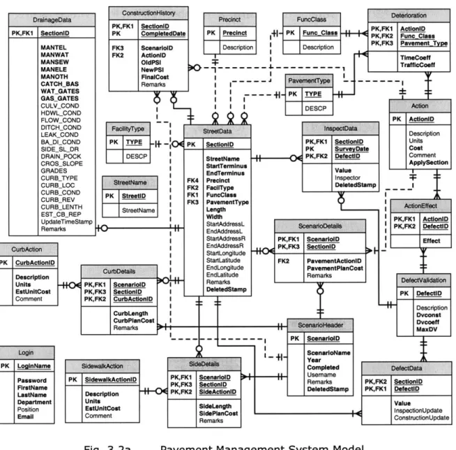
3.2a Pavement Management System Model 55
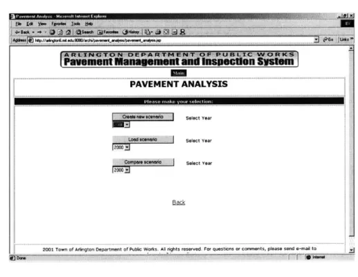
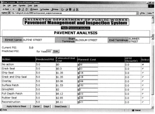
3.2.2a Pavement Analysis Options 56
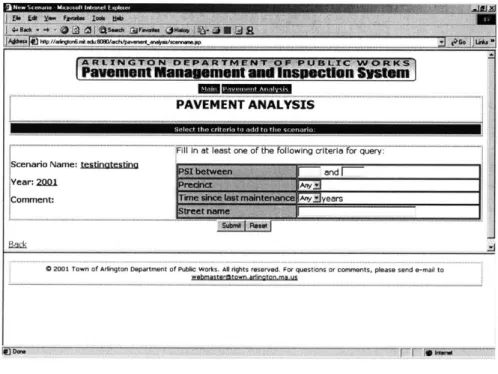
3.2.2b New Scenario is created 57
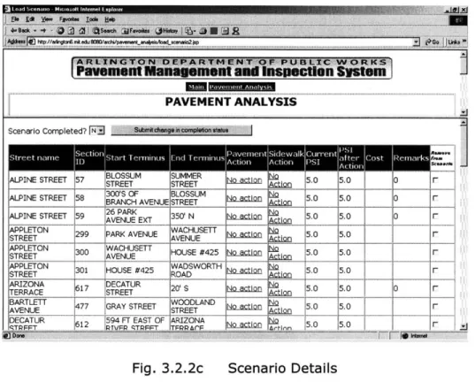
3.2.2c Scenario Details 58
3.2.2d Pavement Action Menu 59
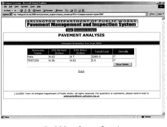
3.2.2e Compare Scenario 60
3.3.1a Street Data Model 61
3.3.1b Sample Data of Street Data Model 62
3.3.2a Pavement Analysis Model 68
3.3.2b Sample Data of Pavement Analysis Model 68
3.3.3a Pavement Condition Model 72
3.3.3b Sample Data of Pavement Condition Model 73
3.3.4a Pavement Management System Model (Completed
Acknowledgement
Sincere thanks are due to Dr. George Kocur, my thesis supervisor, of the Civil and Environmental Engineering Department - Information Technology Group at the Massachusetts Institute of Technology (MIT) for indispensable help with the production of this thesis. Dr. Kocur provided helpful comments and reviewed the development materials.
I am grateful for the opportunity provided by the Public Works Department of Arlington, MA for the development of a pavement management system, especially to Ron Santosuosso of Engineering. This application was used as a case study in the thesis.
Thanks are also owed to my MIT colleagues working for the Arlington Project. My Architecture Group workmates - William Wai Ming Cheung, Wesley Yatlun Choi and Warit Durongdej contributed to the development of the data model for the pavement management system. Thanks are also given to the
Pavement Condition Model Group - Yusuke Mizuno and Sang Hyun Lee - for their contribution of the pavement condition model.
1
Introduction
Most applications today involve the use of data. Some industries such as the financial industry and the marketing industry rely heavily on the information derived from data. In this information technology era, data is a valuable asset to many different industries. The intelligent use of this asset
helps companies with their decision-making.
In the software development process, there are several key stages, most of which involve the data to be used. They are risk analysis, system analysis, data modeling, software product design, development, quality assurance testing and deployment. The objective of this thesis is the introduction of data modeling that is closely related to the result of system analysis. A good data model reflecting the business rules correctly reduces wasted time on software product design and coding. The data modeling process will be described in the first part and then followed by a case study of the pavement management system from the Arlington pavement management system project.
A database is an organized collection of data values. A data model is a specification of data structures and business rules required to support a specific business area. These are the foci of the thesis. Moreover, in order to use the data in a productive way, special care is needed in data collection, data manipulation and data quality.
Summary data for the Arlington database: 1. 90 miles of streets
2. Over 550 streets
3. Over 750 street sections 4. One database
5. 21 tables
6. 26 relationshiis between tables
Fig. la Summary data for the Arlington database
The data model of the pavement management system can be divided into three parts: street data model, pavement analysis model and pavement condition model. In the case study, each individual part will be described in depth and then followed by a description of the combined data model of the whole system. The development of the data model adopted some basic techniques to design a good data model. However, not all the techniques described in the theoretical part were applicable to this case. Compared to the other complicated systems, our data model is relatively simple. Although it is a relatively simple data model, it represents the business and engineering requirements well and it did not impose any significant problems in the coding stage.
2
Data Modeling Theory, Process and Background
2.1 The Development of Relational Database and Data
Modeling
There are several key stages in the development of relational databases and data modeling:
" Flat Files
" Database Management Systems * Hierarchical Model
" Network Model * Relational Theory
* Standard Query Language (SQL)
2.1.1 Flat Files
When computing power was limited in early days, system analysts spent much effort to run a very small program in a limited machine. The programmers at that time tried to store as much data as possible in a single master file. There was one record type to hold all the fields and the master file could be passed to other users. Each piece of the master file had to come with a program that read the file and described its layout. The access methods and descriptions of data of the flat files were left in the programs. Data integrity could not be guaranteed in this approach. The same data was recorded in different locations and accessed by different methods and
formats. When information demands became more sophisticated, a new approach of organizing data was required to replace flat files.
2.1.2 Database Management Systems
A database management system (DBMS) is a database that is a collection of non-redundant data, which can be shared by different applications. The processing program focuses on access strategies, pointers and indexes, which are not the concerns of external users. Thus, the actual storage schemes are not directly accessed by the programs and users. The role of a program is to understand the conceptual schema definition, which is described in terms of entities, attributes, relationships, and the presentation and input of data to and from users. A data model tells how information is
represented and manipulated in a database system. Historically, there have been three main kinds of data models in database applications: hierarchical model, network model and relational model.
2.1.3 Hierarchical Model
In the early 1960s, the business world organized its data using the hierarchical model. Rather than having one flat file as the only record type, some business models need to deal with multiple record types that are hierarchically related to each other. The database keeps track of not only the record types and attributes, but also the hierarchical relationships between them. The attribute that shows the level in the database structure is called the key.
Advantages
" Data is organized in a tree structure.
* Data is accessed easily via the key, but difficult via the other attributes.
Disadvantages
" Tree structure is not flexible.
" Only one to many relationship is available.
2.1.4 Network Model
The network model was proposed in 1971 as part of the work of CODASYL (Conference on Data Systems Languages). In the network model, data structure is separated from physical storage. This eliminates redundant data with its associated errors and costs. In this model, the concepts of a data definition language and data manipulation language are used. Unlike the hierarchical model, many to many relationships are available. This makes the network model more flexible than the hierarchical model. However, there are two restrictions in this model. The first one is that links between records of same type are not allowed. The second one is that a record can be owned by more than one record of different types, but it cannot be owned by more than one record of the same type.
2.1.5 Relational Theory
Hierarchical model and network model were commonly used in the late 1960s and 1970s. The reads and writes of the data files were managed by DBMS while the accessing program managed data access. To browse through the records in a file, the program had to understand a lot about the record arrangements.
In 1969, Dr. E. F. Codd proposed the relational model in his report "Derivability, Redundancy, and Consistency of Relations Stored in Large Data Banks." The main difference is that the relational model distinguishes between a database's file structure and its logical design. In 1970, he explained his relational concepts in his article entitled " A Relational Model of Data for Large Shared Data Banks." The work on the relational theory continued in 1970s but no commercial DBMS adopted it at that time.
Relational Concepts
In the relational approach, pointers, which are used in hierarchy or network structures to set up the linkage and organize the structure of data, do not exist any more. Instead, tables are used to organize the structure of the data.
The basics of the relational approach are:
" Each table contains only a single record type.
" Each record is unique - duplicates are not allowed.
" Records can be arranged in any order - there can be no hidden meaning implicit in the order of the rows of the table.
" A field takes its value from a domain of possible values.
* The same domain is used for all fields in a column and may be used for multiple columns.
" Fields are distinct - no repeating groups are allowed.
* New tables can be produced on the basis of matching field values from the same domain.
With this approach, redundant data is avoided. It allows flexible relationships between data, although many to many relationships are not directly allowed. By having an association table that has two one to many relationships in the middle, a many to many relationship between two tables can be represented.
Relational Model
A data model consists of a number of object types, integrity rules, and relational operators. Relations and domains are the object types. A relation is a table while domain is a pool of data. The integrity rules are a set of valid states of databases that conform to the model. For example, the primary key cannot be null and every foreign key value must match some other existing primary key value. The relational operators are the means of manipulating a database with different instances of the object types. In the relational model,
normalization is required. Normalization is a means to find the simplest structure for a given set of data. There are five rules, or normal forms, that will be discussed later.
Advantages
" Relational model is the most flexible database model.
" This is the basis of an area of formal mathematical theory.
* Storing data from an event into multiple tables and accessing the data afterwards only works if the database was well designed.
Disadvantages
* There is no obvious match of implementation and model.
" The user has to know the content of relations in order to use data manipulation languages.
* A number of tables must be jointly used to get useful information.
2.1.6
Standard Query Language (SQL)
SQL stands for Structured Query Language. SQL is used to communicate with a database. It is the standard language for relational database management systems. In the early days of relational database era, the performance of database management systems was poor. The availability of more powerful computers and the development of data control methods have improved the performance gradually. SQL has become the standard data control method since the 1980s, after IBM released its first SQL based product, SQL/DS.
SQL statements are used to perform tasks in a relational database such as updating data, retrieving data and defining data. Some common relational database management systems that use SQL are: Oracle, Sybase, Microsoft SQL Server, Microsoft Access, and MySQL. Although most database systems use SQL, most of them also have extensions that are usually only used on their system. However, the standard SQL commands such as "Select", "Insert", "Update", "Delete", "Create", and "Drop" can be used to accomplish almost everything that one needs to do with a database. With this standardized database language, we can develop applications using many high level languages such as Java, C++ and Visual Basic by embedding SQL statements into the program codes.
2.1.7 Conclusion
In conclusion, by using the most up to date database tools, there are a number of advantages of a well-designed database system:
" Sharing data - Data becomes reusable after collecting and storing data from different applications.
" Standards and policies enforcement - Naming standards and business policies can be incorporated into the design. A data object or part of the design can thus be reused.
" Security application - Databases can prevent unauthorized access and invalid ways of processing data. Data can be made available to different levels and different people.
" Integrity maintenance - The accuracy and validity of the data can be
improved by using good integrity maintenance features.
" Redundancy and inconsistency reduction - Redundancy leads to higher costs and extra processing.
Database design and data modeling will be discussed more in depth in later chapters and the M.Eng Information Technology Project - Pavement Management System will be used as an example to explain the design of a good database.
2.2 Data Modeling
To build a good database, data modeling is very important. A data model is the foundation for a database to support the business activities. It represents the business rules and ideas. If a good data model were not present, this would result in a flawed database. Databases and data models should be designed to be extensible, expandable and stable. To achieve that, one needs to understand the initiatives for the databases and the business environment. Moreover, the database and data model designer must understand the important issues by listening to the users in order to build an effective database.
2.2.1 Business Rules Expression
Business rules can be reflected by the data model in certain areas. Data constraints are dictated by business policy. Business rules can be incorporated into the database design. Thus, a data model is a precise and formal statement of business rules. To achieve these goals, a data model must be simple enough to represent important concepts clearly and it must be rich enough to cover all possibilities. There is a trade-off between complexity and effectiveness. A data model is an effective medium for
discussions with business people. The data model represents their
requirements and the essentials of the business.
Good practice is necessary to have a well-designed database and the following are some of the key steps.
1. Talk to end-users to find out what they need. Then think about the data and how it will be used.
2. Brainstorming. Jot down words that describe the data. The major entities will map into database tables later on.
3. Look at the grouped data to see if each group has a logical name and a single theme. Carry out 'normalization', which will be discussed in detail later.
4. Think about the groupings and how they are related.
5. Decide on names for the tables, fields and data types for the fields.
2.2.2 Entity Relationship Approach
The concepts of entity and relationship are ways to talk about business needs. This approach was referred to as Entity - Relationship (ER) modeling. Now, many modeling approaches, which emphasize the logistics of the system, are also referred to "ER models". Entities and relationships are used to represent all data and its associations. An entity is something that can be distinctly identified and a relationship is an association among entities.
Advantages
" It is intuitive.
Disadvantages
* It cannot specify some kinds of constraints (for example, maximum number of records).
2.2.3 Data Modeling Phases
Typically, there are three phases in data modeling: conceptual design, logical design and physical design. An Entity Relationship Diagram (ERD) is used in the conceptual design stage to represent the business rules and information requirements. An ERD gives a rough picture of what the database will look like, what kind of data will be stored and what kind of information can be retrieved. An ERD shows what a system can do and not how it does it. There is no process or activity captured in an ERD. Moreover, an ERD should be technology independent. Then in the logical design phase, an ERD is mapped to a table set and the attributes are normalized. The logical design should also be technology independent.
The final phase, the physical design phase, involves implementing the logical model using the specific database technology chosen. The designer needs to make sure that the naming standards conform to the tables and column names in the databases. Another step is to note the columns for indexing. In addition to primary keys, the designer needs to index foreign keys, candidate keys and other frequently accessed columns. One also needs to implement supertype and subtype. Moreover, based on anticipated
activities and use patterns, the designer can plan for file placements on disk. Last, capacity estimation is required before implementing the database.
Data modeling has the following advantages:
" It is a mean of communication - it uses a notation to record and present concepts and constraints.
" It helps elicit and document requirements - it is a precise statement of
requirements and it can be used to determine which requirements need to be changed.
* It reduces the cost to change - it is cheaper to change the model than a completed system. Different trial versions of a model can be used to get the best results. This reduces the efforts and expenses to build the actual product.
Data modeling has the following disadvantages:
" The data model requires a trade-off between precision and
understandability. The designer must take a balance between a business perspective model which talks to humans and a technology model which talks to the computer.
" The data model needs to deal with time and two-dimensional
representation. However, there is no data model language that takes time relationships into account very well.
" The data model is limited by pre-defined symbols and graphical notations. The limited set of symbols make it easier to learn and
understand but it limits the things that can be represented. For example, if a person is weak in vocabulary, he needs more words to express his thoughts that could be expressed precisely by a few words.
2.3 Process of Data Modeling
2.3.1 Model Types
The data modeling language uses different types of models. It allows us to look at a broad area and then refine it in different stages. These model types include:
* Entity Relationship Diagram (ERD)
" Key Based Model (KBM)
" Fully Attributed Model (FAM)
" Transformation Model (TM)
* Database Management System Model (DBMSM)
The ERD, KBM and FAM are used for logical data models. Their scope and level of detail are their differences. When a model is broad, it does not represent lots of detail and vice versa. Because of their natural correlation, the ERD and the KBM are used as architectural models. They set the shape of all models in different stages of development. The FAM is the final form of the logical model in system development. The first three models will be discussed in details.
2.3.2 Entity Relationship Diagram (ERD)
The ERD was discussed earlier and it will be discussed in more detail in this section. As mentioned before, the thorough analysis of requirements is a preliminary step in creating an ERD. The data modeler needs to gather requirements before he can model the data. He gets the information by
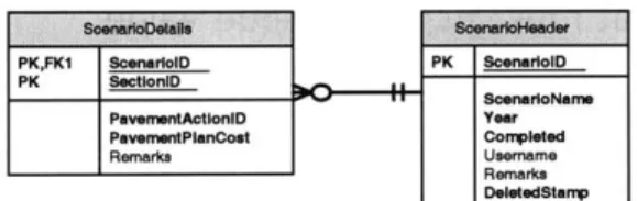
interviewing the clients. During the interview, he asks questions and makes the problem clearer so that he can fully understand the situation. After the analysis, he needs to identify the entities, define entity properties and specify the relationships among the entities. Besides coping with the present needs, he should also consider future developments and direction by looking at the strategic plans for the corporation, the departments and the groups. This will make the design and the database extensible and expandable. If not, the design today may be obsolete. Rectangles are used to represent entities and their properties. Lines are used to represent the relationships and connect entities to entities. In the pavement management system, for example (Fig.
2.3.2a), the diagram shows a scenario header that contains information about a pavement management scenario such as the year and its name. The details consist of the names of individual streets and the pavement actions
planned for each street. The header has many details.
is Composed of
ScenarioHeader ScenarioDetails
Fig. 2.3.2a ERD Example
There are two types of ERD: enterprise ERD and detail ERD. Enterprise ERD contains only entity names and relationships. It does not resolve many to many relationships. It omits entity properties as it aims at providing a general perspective of the database design. The detail ERD is the extension of enterprise ERD. Properties are added for each entity based on the requirements. Many to many relationship is resolved using an associative entity. Reference entities are also used to list values that limit the domain.
Identify and Define Entities
To identify the entities, one needs to ask four 'w' questions:
" Why does the client want the new system?
" What functions does this system need to provide?
" How is the client going to use this system?
* What are the long-term expectations about the system by the client?
Entity modeling helps the designer to know how people to use the data. To have a better definition and description of the static data store, the database designer can create process flow and data flow diagrams. They give a better picture on how the data will be used. We will discuss process flow and data flow diagrams later.
To identify the entities for ERD, it would be helpful to hunt for descriptive names from business sources. A descriptive noun describes an entity which you want to capture and store while a descriptive verb describes activities and interactions between nouns. When defining the entities, descriptions of data need to be identified. The most important source is the end users. By talking to real people, one can get a background understanding of concepts and thus a basic vocabulary of nouns.
In the entity definition, there should be three parts: * A sentence to describe the basic concept
" Several sentences to express the data model and include the business
rules. Some significant attributes, relationships and significant
business rules are described.
" Examples
Process Modeling
The process model shows the structure of activities and how the data flows through the processes. It is a technique to understand what the company does and how it does it.
Unified Modeling Language (UML) is the leading modeling language available to represent the process model. It is a modeling language for specifying, visualizing, constructing and documenting the mechanics and algorithms of a process. UML provides different diagram types such as - use case diagrams, sequence diagrams and class diagrams which can be used to
model all kinds of systems which can be large and complex. It helps to break up complex systems into subsystems in order to overcome difficulties in comprehending such systems. It also provides good models with well-defined semantics, which are essential for communication among project teams and to assure architectural soundness. The use of UML shows a top down functional decomposition of a system and exposes the system's structures. Moreover, it also shows the flow of data through a system, and the work or the processing performed on the data as it moves through the system.
Process modeling is necessary to find out how a system works. This helps to build a reliable, well-functioning and long lasting database. It is a combination of logical and graphical models which describe how a system works.
Identify and Define Relationships
It is reasonably simple to identify the relationship type between entities. Some are obvious but some needs effort to resolve. When entities are joined together to provide information, some forms of relationship can be identified. The sources for identifying entities are basically the same as those for identifying relationships. However, there is one more important source to identify relationship, which is the entity definition.
Cardinality is a qualifier for a relationship that expresses the maximum degree to which two entity types can be related. There are three cases of cardinality:
" Many to many relationship - It is a typical case of relationship cardinality in ERD. Many instances of one entity type relate to many instances of another entity type. In this case, an associative entity standing for this relationship forms two one to many relationships with the two entities.
* One to many relationship - It is also very common in ERD. Many instances of this entity type relate to one instance of another entity.
* One to one relationship - It is rare in a data model. An instance of an entity type relates to one instance of another entity.
The relationships above are maximum cardinality. There is also minimum cardinality. Sometimes it is regarded as the concept of optionality. When a relationship is optional, an instance of an entity type can exist without joining any relationship. For example, one may say that an instance of an entity type 'can' relate to one instance of another entity type rather than relate to one instance of another entity type. On the other hand, a relationship is mandatory if it is not optional. In this case, 'can' is replaced by 'must'.
The definition of relationship should have the following:
* Simple sentences to define the relationship from its elements.
0 Business rules which are conditions that restrict the basic definition.
0 Integrity rules that discuss how the deletion, creation or update of an
entity affect its related entities.
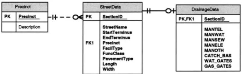
PrecindStret~ata H 0+ --- Dangat
PK Precinct PK Ses PKFK nnonnD SeptionlD
Deecnptlon StreetNaniMATE
StartTwrminue MANWAT
EnP mhu MANSEW
FK1 Preci nct MANyLE
FaniType MANOdt
Func~lm CATCH.DAS
PsvementType WAT.OQATES
Length GA&LGATES
Fig. 2.3.2b Optional one to many and mandatory one to one relationship For example, in Fig. 2.3.2b, Precinct has an optional one to many relationship with StreetData because a Precinct record 'may' appear in more than one place in the StreetData entity. On the other hand, StreetData has a
mandatory one to one relationship with DrainageData because each StreetData record 'must' have a DrainageData record. The figure only shows optional relationships because of the limited function of the modeling software.
2.3.3 Key Based Model (KBM)
KBM focuses on the model architecture. It forms the skeleton of the information system. The use of keys is the fundamental idea of data modeling. In a logical model, key is used to identify an entity instance.
Primary Keys (PK)
The primary key is a unique identifier. Its value is a unique way to distinguish an instance of an entity from the others. No two instances have the same primary key value. The following are the criteria for choosing the primary key of an entity:
" An attribute that must have a value.
" An attribute that must have a unique value.
" An attribute whose value determines the value of other attributes in an
entity.
The first two points are obvious. To look up a distinct record in the database, it must have a unique value, which cannot be null in the primary key. The third point relates to part of the dependency concept in relational theory. More details will be discussed later on this point.
If a single attribute cannot serve as a primary key, a combination of attributes is also possible. A group of two or more attributes can be regarded as a primary key and this is called a composite key. If we have too many attributes which can serve as primary key, we should choose a key what has a stable value, a short value and an enterprise determined value. A stable value means that the value would not change once it is in the database. A short value means that it is short strings and easy to remember or identify. Enterprise determined means the values are controlled internally rather than dictated by an external party.
Foreign Keys (FK)
A foreign key attribute in a child entity is a primary key attribute from a parent entity across a relationship. The attribute(s) is migrated from the parent to child. An FK attribute can act as key or data in the child entity. This tells whether the relationship is identifying or nonidentifying.
PK,FKI ScenarolD PK ScenarlolD
PK SectioniD onroef
PavemntActlonlD Year
Pave PlanCost Cc sileted
Remarks Usefmme
Remarks DetedStamp
Fig. 2.3.3a Primary Key, Composite Key and Foreign Key Example
Identifying Relationships
An identifying relationship specifies that the relationship is identity dependent and existence dependent. Identity dependence means that the
child's identity depends on the parent's identity. In modeling, it means that the FK in child is also its PK. Existence dependence means that the existence
of child depends on the parent's existence. In modeling, if an instance of child exists, an instance of its parent must exist. The above example is an identifying relationship.
Nonidentifying Relationship
A nonidentifying relationship cannot be identity dependent. The FK in a nonidentifying relationship must be in the child's data area rather than key
area. However, a nonidentifying relationship can also be existence
dependent.
In Fig. 2.3.2b, for example, Precinct has a non-identifying relationship with StreetData because the migrated FK Precinct from the Precinct entity is in the data area of the StreetData entity. However, the relationship between StreetData and DrainageData is identifying because the migrated FK SectionID from StreetData is the PK or part of the PK of DrainageData.
Role Naming
The name of migrated FK attribute in the child entity may not fit with the needs in the child entity. To make the role clear in the child, we can
change the name of the FK attribute and this is called role name. Role naming is more critical when there are more than one relationship between two entity types. If the parent entity contributes an attribute twice to the
child entity due to two existing relationships, it would be very confusing
without new role names for both FKs.
Independent Entity
An independent entity is one that does not depend on other entities for its identity. Any FKs are not its primary key. This can also be called a 'kernel' entity, 'fundamental' entity or 'strong' entity. The login entity in Fig. 2.3.3b is an independent entity, which has no relationship with any other entities.
Logjjin~j PK LoginNsms IPasswordI lFiretNeme L&"N sm Position Emai
Fig. 2.3.3b Independent Entity
Dependent Entity
A dependent entity depends on at least one other entity for its identity. There is at least one identifying relationship but can have any number of nonidentifying relationships. An FK is part of its primary key. There are three types of dependent entity. They are a characteristic entity, associative entity and category entity. The first two types will be discussed in this chapter and the category entity will be discussed in a later section.
A characteristic entity is more than a simple entity, which has a single value. It has multiple values and some attributes of its own. It depends on a single parent for both existence and identity. Moreover, it forms a key by
adding one more attribute. This type is very common for representing repeating groups and time related facts. The ScenarioDetails entity in Fig. 2.3.3a is a characteristic entity because it takes ScenarioID as part of its PK from ScenarioHeader entity and adds SectionID to form its composite key.
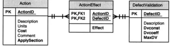
In data modeling, a many to many relationship is usually resolved into two one to many relationships along with a new, associative entity type. The associative entity records any attributes about the association. It represents the association between other entities. Its PK is the combination of the contributed PKs of all its parents. None or one more attribute may need for its PK if there are more than two association instances. In Fig. 2.3.3c, for
example, as Action entity has a many to many relationship with
DefectValidation entity, an associative entity called ActionEffect must be present to form two one to many relationships with these two entities.
Actan AcionEfct DefectVaidation
PIK ActionlO PK,FK1 ActioniD PIK DefectiD
KFK2 D PK Dfeclu
Description Description
Units Effect Dvcont
Cost Dvcoeff
Comment MaxDV
Applyscton
Fig. 2.3.3c Associative Entity
Recursive Relationships
The relationship we have discussed so far is simply an association between two entities which is not necessarily distinct. However, if an entity type is related to itself, a recursive relationship is introduced. There are a few features about a recursive relationship:
" It is nonidentifying.
* It has role named FK.
" It is optional in both directions.
* There are additional business rules, which are stated as part of the relationship definition.
I IlName l
L- - HTit'l Ie .
IDepartmentl FK1 Empoyeanger
Fig. 2.3.3d Recursive Relationship
In Fig. 2.3.3d, for example, a manager, who is also an employee, manages zero or many employees. This is a typical example of recursive relationship.
2.3.4 Fully Attributed Model (FAM)
The FAM focuses on implementation and serving as a non-technical specification of the system's data structures. It extracts from the architecture models for its basics and the details are filled out based on the requirement statements of the project.
Attributes
The attributes are discovered in the same way as entities and relationships. The only difference is that they are record facts which actually store the entity values. Discussion with end users and looking into the data dictionary are still the only way to discover the attributes. It is reasonably simple to do it by looking for the components of the entity.
Here are some guidelines for an attribute:
" It belongs to only one entity. Each attribute represents some facts. Each fact is only associated with one thing.
" It corresponds to a domain. A domain is a defined set of values. An attribute only has one domain which can be shared by many attributes.
* It is a part of the system documentation. Good naming and good use of domain can save some efforts on documentation.
Attributes also have cardinality and optionality aspects. It is possible to have a multi-valued attribute but it is not a practice to do so. Having all attributes with a cardinality of one keeps the model simple and easy to extend. Sometimes an attribute can record 'no value'. For example, when the system cannot recognize the value or the value is not applicable to the entity instance. If an attribute is specified as mandatory, no record will be allowed to be added to the system unless all mandatory attributes are filled, and these attributes cannot be removed at any time. The other non-mandatory attributes may have 'null' values. Null values may cause the following
problems:
* It causes inconsistencies in the implementation. Database
management systems may not define and implement the concept of null. This leads to complexity, unpredictability and inconsistency if we use different platforms.
" There are inconsistencies in evaluation. It is impossible to compare an
unknown value with an actual value.
" Arbitrary treatment is required. Some standards may need to apply for dealing with the inconsistencies mentioned about.
Although there are some problems with optionality of attributes, capturing business requirements accurately should have the first priority.
If the value of an attribute can be computed from other values in the system, it is called derived attribute. In theory, a derived attribute should not exist in the system because the most up to date value can be obtained
whenever it is needed. Derived attributes cause redundancy and
inconsistency in the data model. However, its existence can express the requirements in a clear way. It is also a trade off between simplicity and convenience. The following are some criteria for considering the use of a derived attribute:
" If this fact is accessed very often, it is good to have this attribute in the data model. The business users may think that it is missing or that you have ignored them.
" Derived attribute in the model can be used to document an algorithm or calculation rule which is used to determine its value in the system.
" If an attribute is referred to by rules recorded elsewhere in the model, it must be documented.
" When the derived attribute is derived by some other related values, it would be good to have it in the data model.
* If the derivation of the value involves many resources, it is better to store it in an entity.
Generalization and Specialization
Entities are concepts that are relevant to the system. Some are generalizations of the others while some are more specialized. It would be useful if we incorporated these generalizations and specializations of entities into the data model.
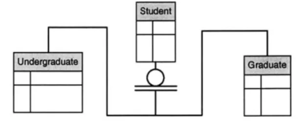
A generalization hierarchy is used to group entities that share common characteristics. The entity type that represents the general concept is called generalization entity. It groups the facts that are in common to all of its instances and it is represented by either a square or puffy box. The top generalization entity can be either independent or dependent. A category entity is an entity type, which specifies additional and different facts. It is represented by puffy box. Moreover, a subtype can also be a supertype of the others. For example, in Fig. 2.3.4a, the Student entity is the generalization entity of the Undergraduate and Graduate entities.
Student
The connection between a supertype and a subtype is called a generalization structure rather than a relationship. It is because the structure of subtype and supertype is the same instance. A Supertype is specialized by its subtype and subtype is generalized by its supertype. In a relationship, the instances are separated and different instances are related. Moreover, a generalization structure is not named explicitly.
A subtype category cluster is a set of one or more generalization structures where the subtypes share the same supertype. An instance of a supertype can only be an instance of a subtype. The subtypes in a cluster are mutually exclusive. A cluster is represented by an underlined circle. An entity can be a supertype of more than one cluster and the subtypes in a cluster are not mutually exclusive of the subtypes in other clusters.
Every subtype must have a supertype. How about the other way round? When an instance of a supertype must be an instance of at least one subtype in a cluster, it is called complete cluster and it is represented by double underlined circle. An incomplete cluster is represented by single underlined circle. In this cluster, an instance of a supertype may be an instance of any subtypes.
A category discriminator is an attribute of a supertype, which contains information relation to a cluster. Its value determines the cluster, which an instance of the supertype belongs to. In a complete cluster, the value of the
discriminator must be present. In an incomplete cluster, it may or may not have a value.
In a generalization hierarchy, one or more entity types can fully describe an instance. Generalization contains the inheritance of properties including attributes and relationships by the subtype from its supertype(s). Subtype inherits the properties of its supertype while it contains its own specific properties. It is also possible to have multiple inheritances in the data model. However, the data model should avoid that because there are potentials for inheritance conflicts.
For example, in the pavement management system, street is a supertype while private street, public street or paper street can be its subtype.
2.3.5 Business Rules Implementation
Business Rule Basics
Vocabulary is used to describe the important things and the rules that constrain and control those things. Terms and facts are the vocabulary of the business. Terms are basic words and they exist as entity types and domain classes of the system. Facts are simple and declarative sentences are associated with terms. These facts are the relationships, attributes and generalization structures of data model. The rules are classified by the scope
of their coverage. The constraint rules must be true and the conditional rules may be true depending on certain conditions.
Integrity Constraints and Unification
Despite limiting the cardinality and specifying a mandatory
relationship, there are also other integrity rules about relationships. These are called referential integrity rules. It means that when a foreign key has a value, that value will match the value of an entity identifier in the system. Referential integrity constraints specify some behaviors. The behaviors include insert, replace and delete. Many database management systems have these behaviors implemented and the programmers and designers do not need to write codes to enforce these rules.
Constraints on relationships are difficult to show in data model. However, unification, a kind of relationship constraint, can be stated in a data model. Unification means two or more foreign keys pointing to the same parent will migrate to the same child. When there are two or more paths of identifying relationships to a child instance from a parent, it is called unification. In unification, same name for the foreign keys from the common parent is used in the child. It can only be used if all the relationships in all paths are identifying. Moreover, it requires that the parent of the instance to be the same.
User Defined Domains and Reference Entities
Constraints on attributes ensure that only valid values are in the database. Four general validation rules can be applied to the attribute's value:
" Individual character
" Value within specification
" Value within context
" Value dependency
The first one is very basic. The system only checks an individual character to see if certain characters are valid. For example, an email
address must contain the character '@'. This is defined using built-in data
types in the system. The second constraint uses domain rules. The attribute value must be within a pre-defined range or conform to the rules of certain algorithms. This is defined with a domain rule. For example, the cost of any construction project must be positive. The third one involves the attribute value, the validation rule and the context of the system at the place where the rule is checked. A typical case is the uniqueness of certain attributes. The last one is the most complex. It depends on the validation of the other attribute values.
We can use user defined domain and reference entities to be the constraints. A user defined domain means that there is a pool of valid data and the input value is checked to see if it presents in the pool. In the
reference entity method, the key(s) in the entity is used to check the validation whenever it appears in the system. The choice between these two depends on how volatile the values are, the source of values and the point of enforcement. The reference entity method is suggested if the values are changed frequently and if the definition of values is controlled internally. Moreover, one needs to check if the database management system supports user defined domains.
Surrogate Keys
In any entity, there must be a unique attribute to identify each individual record. That key can be a meaningful attribute which stores data. It can also be a meaningless and system generated identifier attribute -surrogate key. It is usually used when the original primary key is a composite key. This decreases the size of the primary key and the number of foreign key attributes to migrate in a relationship. The ScenarioID attribute in
ScenarioHeader entity in Fig. 2.3.3a is a surrogate key.
Here are some considerations when choosing a surrogate key rather than a natural primary key:
" A surrogate key should be used if it simplifies the key structures in the model. For example, use a surrogate key if the composite key is too long.
" Surrogate keys are usually created for internal system and internal use. However, sometimes the system users also use the surrogate key
to track something. If a surrogate key is convenient or the business is familiar with it, the modeler should use it.
* A time stamp may be a good surrogate key if time is a useful value in the record. However, it is not natural to many people and different time stamps may be only differ by a very small amount. So a choice must be made depending on the business needs.
2.3.6 Normalization
Normalization is a design standard that shows the database design in normal form specifications. It is also a process of organizing attributes into relation sets. After normalization, anomalies are minimized. The word
'normalization' implies a meaning of making the relationships right. There are
five normal forms (1NF - 5NF). The five normal forms will be discussed in details.
Relational Model and Normalization
An unnormalized table is not a relation. A relation is a table with some special qualifications. A relation must have the following properties:
" One record type in each table
" Fixed number of fields in each row of table
* The value of a field from a domain of possible values * Same domain for all fields in a column
* Unique row
0 Distinct fields
When a table is in the form of relation, it is in its 'normal form'.
Logical Model and Normalization
A logical model represents reality. There are two ways to build a logical model. It can be derived from an accurate ERD. This method gives you a chance to review the ERD. Another alternative is using normalization techniques. A logical model is also platform and technology independent. It represents a normalized design and shows what the database looks like. However, it does not offer any guidance on how to implement the database. It is also a good way to document the database design. It was primarily concerned with the concepts and structures required to support the business
requirements.
Relational Data Analysis and Normalization
The relational data analysis organizes attributes into relations. The relations are used to build data models, which are compared and merged into the logical data model to form the final system. With these processes, the quality of data model is guaranteed and it can be used as the specification of the system. The relational data analysis is a series of steps, which normalize data through the five normal forms step by step. Although there are five normal forms, in many cases, placing entities in the 3NF is generally enough and it is not a common practice to carry out the normalization up to 5NF. In general, there are five conceptual steps to do the relational data analysis:
* Put all data in a single, unnormalized table.
" Choose a key from the unnormalized data.
" Move repeating groups into separate tables (1NF).
" Move attributes not dependent on the whole key into separate tables
(2N F).
" Move attributes which depend on other attributes into separate tables (3NF).
Five Normal Forms
* First Normal Form - This requires that there must be only one value at each row and column intersection. No repeating groups in a table can satisfy the first normal form.
" Second Normal Form - It states that every non-key attribute must
depend on the whole primary key. There is no single non-key column which only depends on part of a composite primary key.
" Third Normal Form - It imposes one more rule than second normal
form. There is no key attribute which depends on any other non-key attribute. It has to be a fact about the primary non-key.
* Fourth Normal Form - It bans independent one to many relationship between primary key and non-key attribute.
" Fifth Normal Form - It implements a principle that eliminates all
redundant data in a table. It is a good practice to break tables into the smallest possible pieces. This allows a better control over the database integrity.
Denormalization
Although it is not common, some system designers may use denormalization to get certain results and it was more common in early days. In early days when the computers were not as powerful as those today, it would take a long time for the system to execute a join table query, i.e. a query that gets data from more than one table. To improve the processing time, redundant data may be added into different tables. This shortens the time for very common queries because only one table is accessed. However, the programmers need to take extra care because when data is changed, the program needs to change the data in more than one place. This is a trade off among efficiencies in processing time, efforts to program common queries and efforts in programming the whole system. However, as computing power (CPU power) has increased in recent years, this is no longer a problem.
Today, the most useful way of denormalization is data warehousing. Redundant data appears in the database so that quick searches on can be carried out without much extra effort in carrying out many algorithms or SQL statements. This is very useful in the internet era and the common e-Commerce sites today, because customized content can be packaged and sent to different customers with short response time from the system. When data is received from the customer, information is generated and is stored in multiple places. However, this requires very careful programming.
2.3.7 Conclusion
This chapter describes a comprehensive process of designing a data model. However, not all steps in the process are applicable to every case or design. Different systems or designs have their own distinct characteristics such as business needs, constraints and complexity, so it is general that different designs adopt a slightly different process to cope with their particular needs.
2.4 Data Modeling in Practice
2.4.1 Data Model in Real World
Data models in real world are usually very large and complex. They may be developed by different groups of people and then integrated at the end. For such large data models, it is impossible for everyone to understand every part of the system. Thus, some techniques are used to deal with a large model in smaller parts while keeping its overall integration and integrity. Two techniques, data model views and user view sessions will be discussed in this section.
Data Model Views
A data model view is a small part of the completed data model for the system. It is useful for complicated relationships in a particular business activity. This technique has three uses:
" Find out missing facts, which are important to the business activity.
" Document all model terms and facts at any level.
" Examine the feasibility of the paths of relationships.
A data model view can have a broad range of levels of detail. Broad view models are useful for modeling an application that is shared across different departments. In this case, view models are developed with each user area and then the results are merged together. A local view model shows the information requirements of a report or query.
User View Sessions
Many projects are completed by groups of people. In a large-scale project, the responsibilities and communication methods of each participant are formalized. Work progress is planned in the user view sessions. People from different groups meet to monitor progress and take the chance for each group to interact with each other in person. This is also a good opportunity to
make important decisions.
In these user view sessions, different groups prepare an individual data view model. To combine every piece into a completed model, the following is needed to follow:
" Identify and solve conflicts such as naming differences, type conflicts,
cardinality conflicts and business rule conflicts.
" Modify a data view model to conform the others. The best data view
model can be used as a skeleton and then other pieces of views can be incorporated into it.
" Merge views. Merge all views together into a completed model after
the modification of all differences.
2.4.2
Data Model Quality
Data Model Quality Considerations
There are three main considerations of data model quality. They are completeness, accuracy and semantics.
" Completeness - A complete data model must include definitions, key
attribute identifications, domain rules, integrity constraints, algorithms for derived data and specifications of data format. Moreover, consistency is also a part of completeness.
* Accuracy - The data model must implement the business rules correctly. This includes not missing important requirements and reflecting irrelevant requirements. Precision accounts for data quality as well.
* Semantics - Proper definitions of the data model components are another key point. Clarity is important.
Data Stewardship
Data stewardship relates to the quality of the model and the data values stored in the system. The concept of stewardship of data includes the use of enterprise data across a wide variety of applications and organizational boundaries. Specifications are needed to define the use of data. It is impractical to allow one person or group to be responsible for the stewardship of the model and its contents. The responsibility should be divided up.
Data stewardship includes three areas of responsibility. They are data definer, data producer and data consumer. Each area of responsibility may consist of business and system components.
A data definer defines the data requirements for adopting the objectives of the enterprise. He ensures that the data is shared effectively. The business side data definers define the meaning of the data. They state the data requirements that implement the business requirements. The system side data definers create and maintain the data model. Both parties work together to establish and maintain the business requirements linked to the data.
Business side data producers create and originate data. They usually perform the business activities and have some linkages with the front end users. They are also responsible for the quality of the data. The system data producers build the database for getting new data. They also give support for physical data security, integrity and access. Moreover, they manage the physical data, and control the access and the use of data.
Data consumers use the data to perform the business activities. They ensure that the modification, use and automation of data do not nullify the values of data. The business role carries out the business activities. The system data consumers define and maintain the system processes.