HAL Id: hal-01816189
https://hal.uca.fr/hal-01816189
Submitted on 26 Jun 2018
HAL is a multi-disciplinary open access
archive for the deposit and dissemination of
sci-entific research documents, whether they are
pub-lished or not. The documents may come from
teaching and research institutions in France or
abroad, or from public or private research centers.
L’archive ouverte pluridisciplinaire HAL, est
destinée au dépôt et à la diffusion de documents
scientifiques de niveau recherche, publiés ou non,
émanant des établissements d’enseignement et de
recherche français ou étrangers, des laboratoires
publics ou privés.
Objects in Domestic and Industrial Applications: A
Survey
Jose Sanchez, Juan Antonio Corrales Ramon, Belhassen-Chedli Bouzgarrou,
Youcef Mezouar
To cite this version:
Jose Sanchez, Juan Antonio Corrales Ramon, Belhassen-Chedli Bouzgarrou, Youcef Mezouar. Robotic
Manipulation and Sensing of Deformable Objects in Domestic and Industrial Applications: A Survey.
The International Journal of Robotics Research, SAGE Publications, In press, 37 (7), pp.688 - 716.
�10.1177/0278364918779698�. �hal-01816189�
Deformable Objects in Domestic and
Industrial Applications: A Survey
Jose Sanchez
1,2, Juan-Antonio Corrales
1,2, Belhassen-Chedli Bouzgarrou
1,2and Youcef
Mezouar
1,2Abstract
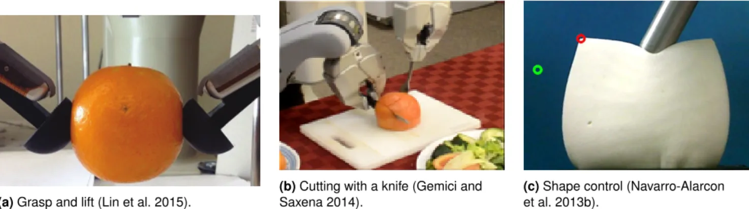
We present a survey of recent work on robot manipulation and sensing of deformable objects, a field with relevant applications in diverse industries such as medical (e.g. surgery assistance), food handling, manufacturing, and domestic chores (e.g. folding clothes). We classify the reviewed approaches into four categories based on the type of object they manipulate. Furthermore, within this object classification we divide the approaches based on the particular task they perform on the deformable object. Finally, we conclude this survey with a discussion of the current state of the art and propose future directions within the proposed classification.
Keywords
Deformable objects, Robotic manipulation, Cloth manipulation, Deformation control
1.
Introduction
Endowing robots with the ability to manipulate deformable objects spawns diverse applications with tremendous economical benefit. For instance, using robots to handle fragile products in the food industry could reduce labor cost (Tokumoto et al. 1999; Buckingham et al. 2001), manufacturing plants could use robots to manipulate flexible objects in order to lessen physically burdens on workers (Acker and Henrich 2003; Rambow et al. 2012) or robots becoming more involved in caregiving activities (e.g. dressing, feeding) for the elder and disabled (Chen et al. 2013; Yamazaki et al. 2014).
Although manipulation and grasping of rigid objects is a mature field in robotics, with over three decades of work, the study of deformable objects has not been as extensive in the robotics community. Another important issue is that many of the techniques and strategies devised for the manipulation of rigid objects cannot be directly applied to deformable objects. For instance, two of the main conditions applied to grasping rigid objects are form closure and force closure. The former consists in applying kinematic constraints on an object such that the object cannot perform any relative motion (Nguyen 1988), and the latter considers a set of contact points such that contact forces can balance an arbitrary external wrench (Bicchi 1995). When it comes to deformable objects, form closure fails to immobilize every
degree of freedom of the object since deformable objects have infinite degrees of freedom (Guo et al. 2013). Similarly, force closure relies on applying a set of forces to restrain the object’s movement based on its undeformed shape. However, the required contact forces applied to the deformable object rely on its deformation (Jia et al. 2011). This entails that the force closure calculation needs to be performed continuously in order to consider the object’s new shape caused by the grasping action.
Furthermore, rigid object manipulation considers mostly the control of the grasped object’s pose, as noted by Khalil et al. (2010). However, the manipulation of a deformable object also needs to address its deformation. This consideration, as well as the inapplicability of the aforementioned conditions, has led to many diverse approaches to handle deformable objects with robots.
In this survey, we review the latest advances on the topic of robotic manipulation of deformable objects. Previous surveys have covered topics such as manipulation of deformable objects in industrial applications (Henrich and W¨orn 2000; Saadat and Nan 2002), or planning the
1Universit ´e Clermont Auvergne, SI GMA Clermont, Institut Pascal 2CNRS
Corresponding author:
Jose Sanchez, Universit ´e Clermont Auvergne, SIGMA Clermont, Institut Pascal, BP 10448, F-63000 Clermont-Ferrand, France
manipulation of deformable objects (Jimenez 2012). Henrich and W¨orn (2000) reported the first attempts of the robotic community to manipulate deformable objects. This was followed by the survey of Saadat and Nan (2002), where the objects are classified based on their shape, material and industrial application. More recently, Jimenez (2012) presented a survey that focuses on object modeling and on manipulation planning of deformable objects. Khalil and Payeur (2010) present a very comprehensive survey, where most of the surveyed papers focus on modeling and simulation, and approaches that have been applied to industrial tasks such as assembly and food handling. However, since these surveys, the field of deformable object manipulation has seen significant contributions.
Our survey focuses on recent advances in the robotics community to address the sensing and manipulation of deformable objects, particularly in domestic and industrial applications. We propose a new classification of deformable objects that not only considers their geometric shape (as it has been previously suggested in (Jimenez 2012; Saadat and Nan 2002)), but also their physical properties. We consider as deformable the objects that either 1) have no compression strength or 2) have a large strain1 or present a large displacement. Objects that have no compression strength are those which do not present any resistance when two opposite endpoints are pushed towards each other. Ropes and clothes are examples of objects with no compression strength.
As noted before, objects can also be categorized based on their geometry. Objects having one dimension significantly larger than the other two, for instance the length of a cable is much larger than its width or height, are considered uniparametric. Biparametric objects are those having one dimension considerably smaller than its other two, for instance the thickness of a paper is negligible compared to its width and height. Finally, triparametric objects represent solid objects. Using these two criteria we classify the reviewed approaches into the following four main categories, as shown in Figure 1:
Type I: Uniparametric objects that either have no compres-sion strength such as cables, strings and ropes; or they have a large strain such as elastic tubes and beams. This type of object are widely referred to as linear in the robotics community.
Type II: Biparametric objects that present a large strain, or a large displacement, such as paper, cards and foam sheets. Also, thin-shell objects such as empty plastic bottles and hollow rubber balls are considered in this
category. In the literature, these type of objects are commonly referred to as planar objects.
Type III: Biparametric objects not possessing any compres-sion strength. Shirts, pants, curtains and fabric sheets are examples of this type of object. These objects are mostly known as cloth-like objects.
Type IV: Triparametric objects such as a sponges, plush toys and food products fall in this object category. Common names used to describe these objects are solid or volumetric. Deformable objects L arge strain T riparam B iparam U niparam N o compression strength U niparam B iparam Physical property Object’s shape
Cloth-like "Linear" "Planar" Solid
Figure 1. Proposed classification of deformable objects.
To further divide the approaches, we group them based on their applications, and three main groups are considered: 1) sensing, 2) manipulation and 3) task-specific. The latter group deals with tasks inherent to the object types. For instance, folding a shirt or tying a knot on a rope. This proposed categorization, based on both object and application type, is succinctly presented in tables that group the approaches for each type of object.
Following this introduction, frequent concepts and terms used in the field of deformable objects are presented in Section 2. Then we review the approaches that focus on type I objects in Section 3, followed by type II objects in Section 4. Section 5 presents approaches handling type III objects and Section 6 focuses on objects of type IV. A summary of this survey and future directions are outlined in Section 7 and finally, our concluding remarks are stated in Section 8.
2.
Fundamentals of Deformation Modeling
This section introduces common concepts and terminology frequently used in the field of deformable object manip-ulation, particularly on object deformation. A deformation
occurs when an external force2applied to an object results in the object changing its shape. Moreover, depending on the response of the object once the external force is removed the deformation can be either plastic, elastic or elasto-plastic.
A plastic deformation entails a permanent deformation, that is, an object maintains the shape caused by a deforming force even when that force is removed. On the contrary, an elastic deformation results on the object returning to its undeformed shape once the deforming force is removed (Callister 2006). Lastly, an elasto-plastic deformation is a combination of both, elastic and plastic, deformations; where the object does not return to its original shape, but it does not hold the deformation entirely. The deformation types are shown in Figure 2.
(a) Before applying
a force.
(b) Making contact
with the object.
(c) Deforming the
object.
(d) Elastic. (e) Elasto-plastic. (f) Plastic.
Figure 2. Top row: a soft object being deformed by an external
force.Bottom row: the resulting types of deformation once the
external force is removed.
Figure 3 shows an object being deformed by a tensile load. The amount of deformation induced by stress is referred to as strain(ε); where stress (σ ) is the ratio between the applied force F and the cross-section area A0(Callister 2006). For
linear elastic deformations3, stress and strain are related by
Hooke’s law (Callister 2006):
σ= Eε
Where E is the modulus of elasticity, also called Young’s modulus, and is measured in pressure units such as Pascal (N/m2) (Askeland and Fulay 2005).
Another important elasticity parameter is the Poisson’s ratio (ν), an adimensional number that relates the ratio between axial and lateral strains (Callister 2006). In Figure 3, the axial strain is represented by the change of length(L−L0
L0 ),
where lateral strains occur perpendicularly to the applied force F.
The Young’s modulus E and the Poisson’s ratio ν are common parameters in modeling the deformation of an isotropic object, where the deformation’s elastodynamics are
L
F
F
L0
A
0Figure 3. A tensile load (F) producing axial and lateral strains. The blue dashed lines represent the original, undeformed, shape and the red solid lines represent the deformed shape (Callister 2006).
represented by a set of partial differential equations solved through discretization techniques in order to approximate the displacement field. However, these parameters are only valid for linear elasticity. Linear deformation can refer either to a geometric or a material linearity. Geometrical linearity is not appropriate for large deformations, since only small deformations can be modeled accurately (Nealen et al. 2006). On the other hand, material linearity refers to a deformation that retains a linear stress-strain relation (Callister 2006).
Modeling a deformation can be done with a variety of techniques. Usually, these techniques required a deformation model and a representation of the object’s shape, usually by a set of particles or a mesh. A mesh represents an object as set of points (vertices), edges and faces or elements for a two dimensional or a three dimensional object, respectively. The faces are usually triangles or quadrilaterals, and the elements are commonly represented as tetrahedra or hexahedra. The deformation models provide a function to compute the position of every vertex based on their current position and an input force (Nealen et al. 2006).
Deformation models4 that do not require a mesh are termed mesh-free (or meshless), and particle based models (Tonnesen 1998) are an example of a meshless model. The mesh-based models are categorized either as continuum or lumped (discrete) variable models, according to the consistency of the mass and stiffness parameters with the approximated displacement fields in the elements of the mesh. The discrete based models are mainly represented as Mass-Spring-Damper (MSD) systems, where the vertices are treated as mass particles and the edges are considered as springs. Continuum based methods are commonly modeled with finite element methods (FEM), where the object is split into a set of discrete geometric parts called finite elements in
order to approximate the object’s shape (Moore and Molloy 2007). A comparison between different physically-based models is shown in Figure 4.
MSD models are more intuitive and simpler to implement than FEM-based models, however FEM-based models are able to produce more physically realistic simulation (Moore and Molloy 2007; Nealen et al. 2006). Furthermore, MSD models present drawbacks such as inability to preserve volume and inverting easily (Moore and Molloy 2007; Sin et al. 2013).
Particle-based
Physically more realistic
Complexity Co-rotational linear FEM Mooney-Rivlin Neo-Hookean St. Venant-Kirchhof Linear FEM Mesh-free Mesh-based Model types Elastic Hyperelastic Material types MSD Nonlinear MSD Dynamically coupled particles Discrete based Continuum based
Figure 4. Comparison of physically-based deformation models
based on the evaluation results from (Sin et al. 2013) and the classification presented in (Nealen et al. 2006).
This section provided merely a brief summary of inter-disciplinary topics that are involved with the simulation of deformations. The interested reader is referred to (Nealen et al. 2006; Moore and Molloy 2007) for more compre-hensive surveys of deformable models and modeling tech-niques in computer graphics. The following references are recommended (Callister 2006; Askeland and Fulay 2005) for a technical review of mechanical properties and elastic behavior.
3.
Linear objects
The first approaches to manipulate deformable objects concentrated mostly on deformable linear objects (DLOs), also called deformable one-dimensional objects (DOOs); such as ropes, elastic rods, beams, cables, etc. One of the reasons for these initial research efforts might be the simplicity of DLOs when compared to planar or solid objects. Also, their simulation is not as computational expensive and assumptions such as modeling them as chains of links allow for simpler algebraic solutions.
The robotic tasks related to DLOs can focus on either sensing, manipulation or a combination of both. Sensing the state of a DLO might require estimating the object’s current
shape, possibly caused by a deformation, or its topology (e.g. sections where an object crosses itself). Manipulation tasks of DLOs include insertion of a cable through a series of holes, untangling a rope, manipulating a tube into a desired shape, and most commonly, tying knots; which remains the most researched task in robotic manipulation of deformable linear objects. The latest approaches dealing with DLOs by a robot manipulator are reviewed in the next sections. Some examples of the tasks involving DLOs are displayed in Figure 5, and Table 1 shows a classification of the reviewed approaches.
3.1
Tying knots
Tying knots tasks require development of dedicated trajectory planning methods and force control strategies. They also require perception abilities to detect, localize and track specific elements in ropes (e.g. intersection points) to monitor the task’s progress. To meet these requirements, sensors able to accurately measure forces, joint velocities and the state of the rope; as well as actuators able to achieve the necessary robot actions, should be carefully chosen.
Yamakawa et al. (2008) proposed a simple description of a rope in order to apply manipulation skills to tie a knot. This description consisted on identifying the intersections created by the rope crossing itself. Furthermore, they utilized a high-speed robotic hand with tactile sensing and a vision system in order to apply the manipulation skills required.
Manipulation primitives are used in Vinh et al. (2012) to perform the task of knot tying. These primitives are identified by observing how a human knots a rope using one hand. Specifically, three primitives were identified: 1) grasping the rope, 2) producing a loop and 3) pulling the rope to create the knot. The robot then followed a set of points, previously extracted from trajectories demonstrated by a human teacher, to perform these primitives. However, the object’s behavior is not modeled and thus, the success of the approach depends only on a open loop execution of these primitives by the robot. Kudoh et al. (2015) extended these manipulation primitives to tie a knot in the air with two dexterous robotic hands (i.e. the fingers are actively controlled). However, this approach is also not robust against disturbance, since no model of the object is derived and no sensor feedback is considered.
Also focusing on tying a knot in the air without a physical model of the object is the work described in Yamakawa et al. (2010). Their approach differs however, on a dynamic manipulation of the rope that relies on high-speed sensors and actuators (1 KHz). The rope was represented as a chain of joints which is algebraically related to the robot’s motion.
(a) Knot tying (Huang
et al. 2015).
(b) String insertion (Weifu
Wang et al. 2015).
(c) Rope untangling (Lui and
Saxena 2013).
(d) Shape
manipulation (Rambow et al. 2012).
Figure 5. Examples of different manipulation tasks performed on linear deformable objects.
Table 1. Classification of approaches to manipulate deformable linear objects using a robot. The state estimation approaches are
divided into discrete and continuous depending on whether they represent the object as a finite set of points/segments or not.
State estimation
Discrete Lui and Saxena (2013); Matsuno et al. (2006); Caldwell et al. (2014)Continuous Javdani et al. (2011); Bretl and McCarthy (2014); Borum et al. (2014)
Manipulation
Shape
control Rambow et al. (2012); Bretl and McCarthy (2014); Yamakawa et al. (2012) Untangle Lui and Saxena (2013)
Insertion Weifu Wang et al. (2015); Yoshida et al. (2015)
Knot tying
Motion
primitives Yamakawa et al. (2008); Vinh et al. (2012); Kudoh et al. (2015) Algebraic
formulation Yamakawa et al. (2010); Takizawa et al. (2015) LfD Lee et al. (2014, 2015); Huang et al. (2015)
Moreover, the position of each joint of the rope is affected by a time delay factor that is proportional to the distance from the joint to the grasping point; that is, the time delay at the grasped joint is zero, while the joints that are farther away get an increasing time delay. By determining this time delay parameter they were able to estimate the configuration of the rope in real time allowing the robot to tie the knot.
Most recently, learning techniques have been applied in order to solve the problem of tying a knot using a dual-arm robot. Specifically, in (Lee et al. 2014) learning from demonstration (LfD) was used to learn a function that maps a pairs of correspondence points (i.e. from a demonstrated and a test scene), while minimizing a bending cost (warping cost). The correspondence points consist of a point cloud representing the state of the rope as a point cloud (obtained through an RGB-D sensor) and the gripper’s trajectories, which were extracted from kinesthetic demonstrations. The bending cost was computed based on the Thin Plate Spline Robust Point Matching (TPS-RPM)5. Also relying on the TPS-RPM to learn a warping function, the approach presented in (Huang et al. 2015) used a convolutional neural network to label parts of the rope such as end-points and crossings.
Another approach, based on a geometric formulation, was proposed by Takizawa et al. (2015) where a dual-arm robot manipulated the shape of a rope in order to tie it around a
pipe. However, their approach did not consider the tightness of the tied knot. This was shown by Lee et al. (2014) to be a necessary condition to ensure the knot stays tied to the pipe. In order to solve this issue, Lee et al. (2015) extended their previous work to incorporate force information into their learning algorithm and thus achieve a sufficiently tight knot.
3.2
Grasping and manipulation
Several tasks that need to manipulate DLOs, such as insertion and shape control, require an accurate estimate of the object’s shape as it is being deformed. This is challenging since modeling and perceiving deformation can be extremely complicated in certain configurations, e.g. when the object is deformed by an unexpected obstacle or when self-occlusion occurs. Several works attempt to overcome this issue.
Based on their previous work (Yamakawa et al. 2010), which assumes the object follows the end-effector’s trajectory if the robot’s motion is fast enough, Yamakawa et al. (2012) were able to deform a rope into different shapes such as a rectangular corner and a semi-circle. The inverse problem of tying ropes, namely untangling ropes, is tackled by Lui and Saxena (2013). The untangling of a rope was performed by a PR-2 robot using RGB-D data to build a graph that represents the object. To build this graph, the points obtained by the RGB-D sensor were grouped in segments by using a region-growing
algorithm which reduced the representation of the rope from thousands of points to hundreds of segments. With this simpler representation, a particle filter was applied to find the best rope configuration for a set of segments. Subsequently a manipulation action was chosen so that the current configuration could be transformed into a desired configuration (i.e. an action that leads to an untangled rope). Another desired robotic task with ropes is that of insertion, which has applications such as needle threading and assembly tasks. Weifu Wang et al. (2015) tackled the problem of inserting a rope, and a string, through a series of holes with tight-tolerance diameters with respect to the rope’s diameter. To achieve this, vector fields were set in the center of each hole to drive the tip of the rope through the hole.
A similar task to inserting a DLO was presented in Yoshida et al. (2015), where an elastic band (O-ring) was extended such that it could be wrapped around a peg. Unlike, the approaches described previously in this section, this approach relied on FEM to simulate the deformation of an O-ring. A motion planning algorithm6, which combined different objective functions such as collision avoidance and minimum deformation, was then used to generate a plan that inserts the O-ring into a peg with a larger diameter, thus requiring the O-ring to be deformed in order to insert it.
Other approaches have focused on deforming a linear object such that it reaches a desired configuration. Rambow et al. (2012) used a two-arm robot to mount a tube in a desired configuration based on a single teleoperated demonstration. The task consisted on manipulating the tube to pass by two constraining walls, thus keeping the tube in the required shape. The demonstration recorded the grippers’ poses and the forces produced by the contacts with the rigid environment. Since a mere repetition of the grippers trajectory does not account for the position uncertainties caused by the physically interaction with the environment, a variable admittance control was applied that allowed for a good tracking of the position when there were no contacts but decreased the tracking’s accuracy to achieve a more compliant behavior, thus maintaining low contact forces while interacting with the environment. To monitor the contact forces, the robot was equipped with a force-torque sensor attached to its end-effector.
A common action among these manipulation tasks is that of reaching intermediate desired configurations in order to accomplish a final goal such as tying, or untangling, a knot. One way to solve this is to use motion planning algorithms. The seminal work of Kavraki with Lamiraux and, subsequently with Moll (Lamiraux and Kavraki 2001;
Moll and Kavraki 2004, 2006), focused on path planning for DLOs and planar objects; where sampling-based roadmap algorithms (e.g. Rapidly exploring Random Tree) were applied to find intermediate configurations of the object to build a plan that reached a specified configuration. The object was described as a parameterized curve and the sampling algorithm chose curves with minimal energy, since these were assumed to represent the most likely configuration of the object. These, and older works focusing on manipulation planning of deformable objects, have been covered in more depth in (Jimenez 2012).
More recently, Roussel and Ta (2014) proposed an approach that incorporated a physics engine to their motion planning algorithm. Here, the DLO was described as a connection of nodes, where the links were modeled using FEM, and the state space was defined by a vector of all the nodes and their positions and velocities. As the physics engine is able to determine the next state of the object based on its current state and an applied wrench, they sampled different control commands (i.e. wrenches applied by a gripper) to find the one that moved the object closer to their goal state. Additionaly, they exploited the enviroment to apply additional external wrenches to the object, and thus reach configurations that would not be possible using only a gripper. In fact, based on the test scenarios presented, allowing the object to contact the environment was necessary to solve the path planning problem. Similarly, Alvarez and Yamazaki (2016) also used a physics engine to simulate the behavior of the deformable object, in combination with a planning algorithm, while allowing a user to modify the simulated environment in an interactive manner. They showed that their planning algorithm was robust against unexpected changes to the environment. An extension of these approaches was recently described in (Shah and Shah 2016), where a set of interlinked cables is manipulated into an array of clamps. This problem requires the motion planning algorithm to handle an extra constraint, namely that the interlinks between cables do not become taut. They defined a series of actions for two available manipulators that were only allowed to grasp a finite set of points on each cable. Then their planning algorithm searched for the combination of actions that solved the clamping task without violating the constraint of overstretching the interlinks.
Although these approaches might be helpful to other tasks, as they solve the motion planning required to attain desired configurations; they have, so far, not been shown to work in real time as finding an adequate plan usually requires long times (e.g. minutes). Furthermore, these works have only been tested on simulation environments where the object’s
behavior, and its interaction with the environment, are greatly simplified.
3.3
Deformation sensing
Estimating the necessary parameters of a linear deformable object to manipulate it is a crucial issue. Several approaches have been proposed with different objectives. For some of them, the objective was to perceive the configuration of the object (e.g. are there knots or intersections? and, if so, where are their locations?); other works have focused on estimating the global shape by either learning parameters that describe the object’s deformation or by describing the object in geometric terms. Depending on the approach, different assumptions are required as it is noted below.
Matsuno et al. (2006) were able to estimate the state of a rope using a topological description, that is, the rope was described as a node graph. The nodes of the graph represented either the ends of the rope or intersections. In order to distinguish whether the side of the rope was passing over, or under, they used the luminance variance on an image obtained by a stereo vision system.
A more recent approach that is able to perceive the deformation of a one-dimensional object, such as surgical suture, was presented in Javdani et al. (2011). Using a stereo vision system together with a simulator, they were able to predict the configuration of the object. Specifically, they learned a set of parameters that minimize an energy function that considers the bending, twist and gravity effects on the object. However, this approach assumes the object does not stretch, that is, its geodesic distance remains unchanged while being deformed.
Also relying on a simulation, Caldwell et al. (2014) estimated the stiffness parameters of a flexible loop. Rather than incorporating visual information, proprioception sensing (i.e. joint values and forward kinematics) was used instead to compare with the simulated values of the object. The object was represented as a series of rigid links connected by springs, and the optimal values for the springs’ stiffness were found by optimization of an error function given by the difference between measured and simulated values.
An analytic formulation to estimate the shape of a flexible tube was proposed by Bretl and McCarthy (2014). They assume, however, that the tube cannot be stretched and is held at both ends. The object was described as a Kirchoff elastic rod, where the elastic energy is computed based on three scalar functions that measure strain. When the object is in static equilibrium, its shape can be described by geometrically solving an optimal control problem. With
this formulation they were able to describe the possible equilibrium configurations of the object, based on the poses of the end-effectors holding each end, using a single global chart7; and thus, estimate the configuration of the object. This theoretical framework was later evaluated in simulation and experimentally on a two-dimensional case, that is, the deformation was restricted only to remain on a plane (Borum et al. 2014).
4.
Planar objects
In this section we review approaches used on planar objects, such as printing paper, cards, tennis balls to name a few. Most of the research, especially at the beginning of this sub-field, has focused on these type of objects as a simplified version of three-dimensional objects, e.g. in a simulated environment.
The two most studied manipulation tasks on a planar object are grasping and controlling its deformation. The former consists of positioning the fingers of a robotic manipulator on the object such that the manipulator is able to lift it and hold it in the air, while the latter consists in changing the shape of the object into a desired configuration. Other tasks have concentrated on more specific tasks such as paper folding, manipulating the pose of the object by relying on its deformation (e.g. rotating a pizza dough-like object and reorienting a bill) and sensing the state of a deformed object. Table 2 summarizes the approaches reviewed in this section.
4.1
Manipulation
The works on manipulation of planar objects can be classified into three groups, namely, paper folding, grasping and rotating an object. Each group raises distinct challenges due to the different types of objects they manipulate (e.g. a sheet of paper vs a thin sponge) or the specific task they focus on. Paper folding requires the robot to perform precise motions to ensure the paper is being held firmly and bent in an appropriate manner. To grasp and pick up an object, the robot must have the ability to decide where to grasp the object and how tight it should hold it. This would require different grasp forces depending on the material type, whose properties might not be known in advance. Finally, approaches that focused on rotating objects have either exploited the environment or made use of the object’s own dynamics. In the following, a review of works that address this type of manipulation are presented.
4.1.1 Paper folding A clear example of paper manipula-tion is origami, which Balkcom and Mason (2008) addressed
Table 2. Classification of approaches that focus on planar objects.
Manipulation
Grasp Guo et al. (2013); Jia et al. (2011); Gopalakrishnan and Goldberg (2004) Gopalakrishnan (2005); Jia et al. (2013, 2014)
Pick up Jia et al. (2014); Elbrechter et al. (2011); Kristek and Shell (2012) Rotation Kristek and Shell (2012); Ramirez-Alpizar et al. (2012)
Paper folding Balkcom and Mason (2008); Elbrechter et al. (2012) Namiki and Yokosawa (2015)
Shape control
Single point Das and Sarkar (2010, 2013)Multiple points
Wada et al. (1998); Hirai et al. (2001); Fanson and Patriciu (2010) Das and Sarkar (2011); Kinio and Patriciu (2012); Berenson (2013)
Sensing
Parameter
identification Boonvisut and Cavusoglu (2013) State
estimation Tian and Jia (2010); Schulman et al. (2013); Boonvisut and Cavusoglu (2014)
using a custom made robotic system that is able to perform a sequence of folds resulting in an origami pattern (e.g. a paper plane). The system consisted on a four degrees of freedom arm, a suction pump to hold and move the paper, and a base with a clamp that holds the paper while the arm folds it. As no sensors were used by the system, the arm motions were performed in an open loop as selected by a simple bread-first search algorithm. Since this approach relied on applying a sequence of predefined folds to the paper, no dexterous manipulation of the paper was performed.
On the contrary, Elbrechter et al. (2011) presented an approach to first grasp a paper resting on a table with a bi-manual robot equipped with a five-fingered hand, and they later extended their approach to fold the paper (Elbrechter et al. 2012). Both approaches rely on a vision system with 5 calibrated cameras that tracked the position of a set of fiducial markers on both sides of the paper. Furthermore, they simulated the paper’s deformation with a physics-engine, where the paper is modeled as a 2D grid of nodes. The extension of the latter approach consisted on adding a connecting link between all neighboring nodes. Each link in the physics-engine was represented by a distance and a stiffness coefficient. The stiffness coefficient is decreased if a crease line, detected by the vision system, passes through any given link. Thus, the links which cross a crease present a higher deformation and can render the folding of the paper.
A similar approach, also using a bi-manual robot system, based on integrating visual information into a physics-engine simulation was presented in (Namiki and Yokosawa 2015). However, the paper was modeled with a mass-spring-damper model. Furthermore a set of dynamic primitives was used to apply folds to the paper. Unlike the approaches proposed in (Elbrechter et al. 2011, 2012), the paper is not covered with fiducial markers. Instead the corners are marked with different colors to allow the vision system to detect them.
4.1.2 Grasp and pick up We consider a grasp as the action of holding an object through contact points, while a pick up is a subsequent action that lifts the grasped object from a supporting surface. One of the first works on grasping flat deformable objects was done by Gopalakrishnan and Goldberg, where they present an approach that extended the concept of form closure for rigid objects to deformable planar objects (Gopalakrishnan and Goldberg 2004; Gopalakrishnan 2005). They assumed that a set of contacts, e.g. the grippers of a robot, holding a rigid object in form closure would also hold a deformable object in deform closure. Deform closure was defined as a set of contacts holding an object such that an increment of potential energy is required to release the object. Here, the potential energy is proportional to the amount that the gripper deforms the object. In order to determine the potential energy, an FEM model of the object and its stiffness matrix were used to compute the internal forces based on the object’s deformation.
Also relying on an energy-based formulation and using an FEM model Guo and Jia, in a series of papers, focused on grasping planar deformable objects using only two fingers. Their formulation of potential energy, which later they relate to work, is based on the distance traveled by the fingers times the force they apply to the object. The translation of the fingers is described as squeeze grasping, where one finger moves towards the other while both maintain contact with the object. In (Jia et al. 2011), they applied this approach only to hollow objects (e.g. ring shaped objects), thus considerably reducing the computation complexity as the FEM was only simulated on segments describing the object’s boundary rather than on elements describing a solid object. This was extended to solid planar objects in (Guo et al. 2013) where they also defined the finger contacts as a set of points that either stick or slip, in which each of the points coincides
with a node of the object’s mesh. In order to determine whether a contact is sticking or slipping, they check if its friction cone rotates after a change in the squeeze depth8(see Figure 6). Based on the state of each contact point (i.e. either sticking or slipping) they were able to infer, for instance, if the object was slipping out of the grasp. Based on the nodes that were in contact, as well as their contact type (stick/slip), they computed a reduced stiffness matrix which significantly reduced the computational burden.
Later on, they introduced grasp metrics that can be applied to deformable objects, namely they defined the concept of pure and stable squeezes (Jia et al. 2013). A pure squeeze is defined as a grasp that generates only deformation (i.e. no translation or rotation are generated while squeezing); a stable squeeze is a squeeze along a vector such that minimizes the potential energy on the object (i.e. for all the grasps with the same squeeze depth, the stable squeeze is the grasp that generates least deformation). Additionally, they proposed an optimal method to resist a third finger that tries to push the object out of the grasp by moving the two grasping fingers such that the object remains grasped and the work they apply is the minimum required. Figure 6 shows an example of a squeeze grasp. It also shows a peculiarity of deformable objects, namely, the contact point grows into a contact area as the grasp progresses. Finally, Jia et al. revised the works described in (Jia et al. 2011; Guo et al. 2013; Jia et al. 2013) and presented an extensive and self-contained manuscript detailing their approach to grasp a planar deformable object using only two fingers (Jia et al. 2014). However, their work does not considers dynamics, nor gravity, while computing the FEM simulation. Furthermore, because the analysis is based on the assumption of linear elasticity, large deformations cannot be accurately described.
Figure 6. A two-finger grasp (a) before and (b) after a squeeze
grasp. The points represent contact points, white ones are in slip mode and black ones in stick mode (Jia et al. 2014).
4.1.3 Rotation Another form of manipulation that does not require the object to be grasped is that of nonprehensile manipulation. For instance, Ramirez-Alpizar et al. (2012)
presented an approach that is able to rotate a deformable planar object, resting on a plate attached to a robot’s end-effector, using dynamic motions consisting in rotating around and translating along a single axis of the plate as shown in Figure 7. They represented the object as a mass-spring-damper model able to describe bending and compression. The elasticity parameters were estimated by experimentation. Although their approach exploits the deformation of the object in order to rotate it on the plate, it is not able to control the deformation, e.g. to reach a desired configuration of the object. Similarly, Kristek and Shell (2012) also proposed a method to rotate planar deformable objects using two grippers, however the applied gripper motions consisted of a set of actions that are executed in an open-loop manner as they do not use any sensor. They evaluated their approach using planar objects such as a dollar bill, a card and various shapes of a foam material. This approach used two grippers that exploit the environment to facilitate the task of rotating the object. The first gripper controlled only one degree of freedom that slides a board so as to sweep the object against a wall in order to bend it enough thus, allowing the second gripper to grasp the object and subsequently rotate it.
Figure 7. TheXarrow shows the translational movement and theΘarrow the rotational motion. Image extracted
from (Ramirez-Alpizar et al. 2012).
4.2
Deformation control
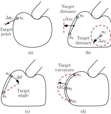
This section focuses on approaches that address the problem of controlling the deformation of planar objects in order to achieve a desired shape. These approaches define this deformation control problem with the objective to move a target point, or a set of target points, located on the object such that once the target point reaches a specified position the overall shape of the object approximates the desired deformed shape. Thus, they indirectly control the
deformation of the object through a target point, or a set of target points.
This type of problems are sometimes referred to as indirect simultaneous positioning (ISP) problems, a term proposed by Wada et al. (1998). They were one of the first researchers to address the problem of not only grasping a deformable object, but also actively controlling its deformation (Wada et al. 1998; Hirai et al. 2001). Here, the object was modeled as a mesh where the nodes are connected with springs and two sets of points (coincident with the nodes of the mesh) are defined, namely, controlled and manipulated points. The controlled points were located inside the object and were tracked by a vision system to represent the deformation of the object. The manipulated points were the contact points between the fingers of a manipulator and the object. Thus, they were able to indirectly control the deformation of the object by moving the manipulated points such that the controlled points reach a desired configuration. Recently, there have been several works attempting to solve the ISP problem. These approaches control the position of several points (multi-point control) as first proposed in (Wada et al. 1998), or they focus on controlling one internal point on the object (single-point control).
4.2.1 Single-point control Das and Sarkar (2010, 2013) used three robotic fingers to deform an object such that a single internal point on the object reaches a desired position. They solved this problem using a control system that consists of a trajectory generator, a controller for each finger and the object. The finger controller is a PI controller that computes forces based on a positional error and the trajectory generator computes the desired velocities of the fingers to reach the desired position of the target point, both of which are user defined. In order to guarantee stability, a passivity observer monitored the energy applied by each finger controller to the object and two passivity controllers were placed at the input (trajectory generator side) and the output of the finger controller to dissipate any excess of energy. They only presented simulation results were the object’s deformation was modeled using a Mass-Spring-Damper system with known coefficients.
4.2.2 Multi-point control Fanson and Patriciu (2010) proposed a method, based on the concepts of manipulated and controlled points as described by Wada et al. (1998), that linearizes the deformation model. The model was linearized around the origin, i.e. the object’s undeformed state, by using one state variable that describes both the position of the points along with their velocities. Having this formulation they designed an output regulator that drives the control
points to a desired configuration. In order to compute the position of the control points based on the force applied at the manipulation points, the object was modeled as a mesh-free particle system using the reproducing kernel particle method (RKPM) (Chen et al. 1996). Although their approach was formulated to manipulate and control several points simultaneously, in their evaluation they used only a single control point and a single manipulation point. Afterwards, Kinio and Patriciu (2012) used an H∞controller
instead and modeled the object using an FEM based model. In their evaluations they used two control points and two manipulation points.
In (Das and Sarkar 2011), a Mass-Spring-Damper model was used to simulate a deformable object where the links between nodes are modeled as a Kelvin-Voigt model in series with a damper. This model was used to deform a planar object such that its shape, as described by a curve, can be changed into another desired shape. This approach, however, requires a significant amount of manipulation points9 to achieve acceptable results.
Instead of relying on a model, Berenson (2013) proposed a model-free approach to manipulate an object, grasped by a set of grippers, into a desired configuration. The object was described as a set of points. Additionally, it is assumed that the points of the object that are grasped by a gripper do not move with respect to that gripper. Thus, the position of the points farther away from a gripper are affected less by the gripper’s motion. This assumption, termed diminishing rigidity, was then used to compute an approximate Jacobian that relates the motion of the points with respect to the grippers’ motions.
This approach was recently extended in (McConachie and Berenson 2016) by choosing among a set of models for this Jacobian using a multi-arm bandit formulation. Under this formulation, the “arms” were defined as models based on their diminishing rigidity and an adaptive Jacobian (as proposed by Navarro-Alarc´on et al., see Subsection 6.3) with various sets of parameter. Although they presented simulation results on a rope and a cloth-like object this approach is better classified based on the task it performed, namely multi-point control, since the task considered by these approaches focused on reducing the overall distance between a set of target points T and a set of points P defined on the object.
4.3
Deformation sensing
These approaches focus on either determining the object’s physical parameters during a deformation or estimating the state of the deformed object. In the former case, the
parameters are required as input for the object’s deformation to be simulated; while the latter might make use of these parameters, they can also rely solely on the output of devices like cameras or force-torque sensors. An example of an approach to identify deformation parameters was proposed by Boonvisut and Cavusoglu (2013), where the elasticity parameters of a soft tissue phantom are estimated. In order to estimate the elasticity parameters, they minimized an objective function that reduce the difference between an observed deformation and an FEM simulation. The observed deformation was obtained by a stereo-vision system that tracked a set of markers on the object, while the inputs to the FEM simulation consisted of force and positions measurements obtained while manipulating the object.
Instead of only identifying parameters, other approaches used these parameters in physical models to track deformations of an object. One such example was reported in (Tian and Jia 2010), where the deformation of thin shell objects, such as a tennis ball, is tracked by an FEM simulation that is based on shell theory (Timoshenko and Woinowsky-Krieger 1959). Schulman et al. (2013) instead used a probabilistic model in combination with a physics engine simulator to account for parts of an object that might not be visible to a depth range sensor. The output of the depth range sensor consists of a set of observable points which were used to infer the set of points that conform to the physical model of the object in simulation. Although the proposed algorithm was able to track objects in real time, between 20 and 50 Hz; there is no chance to recover if the algorithm diverges.
Another application on estimating the state of a deformable object was presented in (Boonvisut and Cavusoglu 2014), where the constrained boundaries of an object were predicted by manipulating the object with a robot gripper. The object’s boundary was separated into three sections; namely, a fixed one, a second one that is free to move and a third one that is manipulated by the gripper. Stereo vision, together with an FEM model, were used to track a set of points (nodes) on the object. The nodes were then grouped into patches to reduce dimensionality. With the object represented as a collection of patches, a hill climbing algorithm was applied similarly to an occupancy grid problem in order to estimate which patches are the fixed ones.
5.
Cloth-like objects
In this section we review clothes and fabric materials such as towels, sheets, rags, etc. Most of the approaches that
deal with cloth-like objects have focused on solving one or more tasks from the pipeline described in Figure 8. The first step requires the robot to locate the clothing item, possibly identify its configuration, and decide where to grasp (e.g. a shirt’s collar). Next, the robot needs to grasp and pick up the item and, depending on the desired task, perform a preparatory action such as extending, or untangling, the garment or laying it flat on a surface. Finally, the end-task might consist on folding or hanging the item in order to store it or putting the item on a person (i.e. clothing assistance).
Moreover, these approaches can be grouped into three major types of tasks, namely, sensing, grasp/manipulate and cloth-specifictasks. The sensing tasks are mainly concerned with recognizing the state (e.g. the shape) of the garment, or detecting ideal grasp points for further manipulation. The grasp/manipulate tasks handle issues such as picking up clothes and bringing them into a desired configuration (e.g. lay them flat on a table). Finally, cloth-specific tasks refer to tasks such as folding and hanging clothes items as well as aiding disable people with their dressing. A classification of the reviewed approaches is summarized in Table 3.
5.1
Sensing
5.1.1 State estimation One of the most important challenges, regarding sensing for cloth-like objects is self-occlusion. As clothes tend to easily crumple, key features might be covered by the object itself. We describe below how previous approaches have dealt with this issue. Kita et al. (2011) used vision sensing and simulation to recognize the shape of a garment while being held by a humanoid robot. The vision system provides 3D visual data used in combination with a simulation to estimate the deformation based on the object’s size and softness. The result is a set of possible shapes defined by the point where the object is grasped. The robot reduces the uncertainty between the possible shapes by regrasping the cloth by its rim.
The configuration of different garments (e.g. sweater and shorts) is estimated using depth data acquired while a robot manipulator rotates the garment in the approach proposed by Li et al. (2014). The depth data is used to reconstruct a 3D mesh model of the garment. The reconstructed model is compared with the mesh models of a database to obtain the most similar one. This similarity is based on the Hamming distance between two binary vectors representing the reconstructed model and each model in the database. To construct the binary vector, a bounding cylinder is fit to the mesh model and the cylinder is subsequently divided into sections. Each section represents a binary number indicating whether or not a part of the object is in it. By concatenating
Detection/estimation Grasp Preparation
Fold Hang Clothing assistance
Figure 8. Pipeline describing the common tasks of robotic cloth manipulation.
Table 3. Classification of approaches to manipulate cloth-like objects using a robot.
Detection/
estimation
State estimation
Lee et al. (2015); Huang et al. (2015); Kita et al. (2011); Yamazaki (2014) Bergstrom et al. (2012); Li et al. (2014); Cusumano-Towner et al. (2011) Maitin-Shepard et al. (2010); Bersch et al. (2011); Twardon and Ritter (2015) Grasp point
detection
Kita et al. (2011); Ramisa et al. (2012); Yamazaki (2014)
Mons´o et al. (2012); Maitin-Shepard et al. (2010); Bersch et al. (2011)
Grasp
Grasp / liftLee et al. (2015); Huang et al. (2015); Kita et al. (2011); Cusumano-Towner et al. (2011) Maitin-Shepard et al. (2010); Bersch et al. (2011); Twardon and Ritter (2015)
Ramisa et al. (2012); Mons´o et al. (2012); Shibata et al. (2009)
Manipulation
Separate Maitin-Shepard et al. (2010); Mons´o et al. (2012)
Untangle
Lee et al. (2015); Huang et al. (2015); Cusumano-Towner et al. (2011) Maitin-Shepard et al. (2010); Bersch et al. (2011); Twardon and Ritter (2015) Doumanoglou et al. (2014); Li et al. (2015a)
Lay / flatten Lee et al. (2015); Huang et al. (2015); Maitin-Shepard et al. (2010) Li et al. (2015a); Sun et al. (2015); Kruse et al. (2015)
Final task
Fold
Lee et al. (2015); Huang et al. (2015); Maitin-Shepard et al. (2010) Bersch et al. (2011); Yamakawa et al. (2011); Miller et al. (2012) Stria et al. (2014); Balaguer and Carpin (2011); Li et al. (2015b) Hang Twardon and Ritter (2015)
Clothing
assistance Yamazaki et al. (2014); Tamei et al. (2011)
the sections, a binary vector describing the three-dimensional garment is formed.
Another application for estimating the state of garment can be found in (Bergstrom et al. 2012), where the focus is on estimating the folding of an article (e.g. a T-shirt and a piece of cloth). In order to determine the folding state of the article, they estimated its contour using a Hidden Markov Model (HMM) based on a single feature. This feature is extracted from a sequence of images and consists of an histogram of distance between each point on the object’s contour to the rest of the contour points which is referred to as Shape context. This representation is much more compact and thus it allows for a fast estimation of the article’s shape. Although a lot of local information is lost with this sparse representation, the use of temporal information proved to be more informative for correctly estimating whether or not an article was fold correctly.
Besides the configuration, other interesting characteristics to understand the behavior of a garment are its material and fabric pattern. For instance, a laundry robot would decide either to use warm water for jeans or cool water
for woolen items. This problem was tackled by Kampouris et al. (2016) using a multi-modal approach that combined RGB-D, photometric and tactile data. They applied a variety of machine learning algorithms such as Support Vector Machines, random forests and HMMs; and then fused the results using a majority voting. Although their results showed that the combination of modalities was the most accurate for the majority of the test cases, there were particular cases where either using only photometric or tactile data was clearly more accurate; showing the need for a better fusion strategy.
5.1.2 Grasp point detection The previous approaches rely on holding the garment in the air in order to estimate its configuration. However, before the robot holds the garment, it is necessary to grasp the garment from a possible crumpled configuration (a more likely state for clothes that have been taking out of the drier or dropped on a table). Thus, in order to grasp a crumpled garment a robot must first decide where to grasp.
Ramisa et al. (2012) tried to solve the issue of grasping polo shirts by detecting their collar. They used a Bag of Features (BoF) that is generated with SIFT features from a 2D image and a histogram based on depth data. They achieved decent results where only one polo shirt was present, although when other types of garments (such as pants and t-shirts) were in the field of view of the camera, the accuracy rate reduced drastically (from ∼70% to ∼30%).
Also focusing on selecting grasp points, Yamazaki (2014) proposed an approach based solely on depth data to pick up a crumpled cloth. The object was represented by the edge of the cloth, along with creases created by wrinkles, as perceived by the depth data. Thus, this contour (edges and creases of the cloth) is described by points obtained from a depth sensor. Then, each point on the contour is compared to grasp points from a training dataset in order to select the most similar point to any grasp point in the dataset. This training dataset was generated with manually assigned grasps from a set of sample images.
5.2
Grasping and manipulation
Depending on the manipulation task and the particular state of a clothing article, the robot is required to handle the article in a particular fashion. For instance, if the article needs to be flatten or stretched in order to remove wrinkles, multiple regrasps might be required such that the article is held by opposite corners. The following works focused on manipulation tasks that consider different starting configurations for the articles (e.g. crumpled or lying flat).
5.2.1 Grasping for garment picking-up A geometric approach to picking up a cloth is described in (Shibata et al. 2009), where a robot generates a wrinkle by deforming the cloth so that the robot can grasp the cloth. They defined the concept of wiping deformation, which consists in moving the jaws of the robot’s gripper towards each other while maintaining contact with the cloth. In this way, the cloth moves with respect to the surface but there is no relative motion between the cloth and the gripper at the contact points. However, this approach assumes the cloth is lying flat on a surface, a scenario that is rather uncommon since cloth-like objects tend to easily crumple.
Not relying on the assumption of the object lying flat, Mons´o et al. (2012) used a robot manipulator to separate clothes. They considered the inherent sensing uncertainty to solve this problem using a partially observable Markov decision problem (POMDP). Here, the state is represented by the number of clothes on two sides of a table. The actions consist of either moving a piece of cloth from one
side of the table to the other, thus reducing uncertainty, and removing a piece cloth from the table once the uncertainty is below a threshold. Picking more than one piece of cloth is considered a failure. Observation and transition models were obtained experimentally. Lastly, the goal was defined as removing all the clothes from the table with the least amount of manipulation actions.
5.2.2 Manipulation for garment reconfiguration Cusumano-Towner et al. (2011) sought to bring a clothing article into a desired configuration using a PR2 robot. To do so, they used a HMM, a cloth simulator and a planning algorithm. The HMM is used to estimate the garment’s configuration, where the hidden state only includes the article’s category and size, and the grasp points for both grippers. These grasp points represent the nodes of the garment’s mesh model, according to the cloth simulator, where the gripper is grasping the garment. The robot then repeatedly regrasps the garment using the planning algorithm, which relies on the garment state output by the HMM, until the cloth is brought into a known configuration. Once the configuration of the piece of cloth is known, although not the desired one, the robot regrasps the object to bring it to the desired configuration (e.g. holding a shirt by its shoulders).
Doumanoglou et al. (2014) were able to solve this problem much faster by reducing the number of manipulation actions required to reach the desired configuration of a garment. Using a robot platform with two arms they begin by grasping the garment at a random point with one arm and let it hang to allow the other arm to grasp the lowest hanging point of the garment, e.g. at the end of a sweater’s sleeve. Then, the robot releases the first grasp to leave the cloth is hanging by one of its ends. Once hanging, the robot uses a POMDP to continuously rotate the garment until a desired grasp point is detected and it can be grasped by the free arm. This procedure is repeated for the second arm. Thus, allowing the robot to unfold the article by extending it by the two grasped points. To determine the two desired grasp points they used Hough forests, which are random forests using a generalized Hough transform (i.e. able to detect arbitrary shapes). To reduce the number of locations of possible grasp points, they divided the object’s bounding box in an 8 × 8 grid.
With help of a thin-shell simulation, Li et al. (2015a) also proposed an approach to unfold clothes. They first simulate mesh models of the garments while they are grasped at different points (e.g. neck, sleeves, etc.) and let them hang loose under only the effects of gravity in a physics engine. Next, they built a database out of these models and use it to
compare it against the sensed data, which consists of depth-data from multiple-views acquired by rotating the object back and forth. To reconstruct the model based on these data, they use Iterative Closest Point (ICP) to first apply a rigid registration and then a non-rigid registration; where the rigid registration considers only translation and rotation between the sensed data and the modeled data, and the non-rigid registration accounts for the deformation of the garment. Once the model has been reconstructed they are able to grasp the required points on the garments, for instance the elbows of sweater, to unfold them.
Besides unfolding a piece of cloth, or bringing it to a desired configuration, some approaches rely on the garment to be laying flat on a surface. Sun et al. (2015) attempted to solve this task, where a two arm robot stretches a piece of cloth to flatten out the wrinkles. This approach uses RGB-D data to detect and locate wrinkles on the cloth and subsequently plan the required motions for the robot’s arms to remove the wrinkles. The wrinkles are described as fifth order polynomial curves and they are assigned a weight based on their volume. The largest wrinkle is then selected to be flatten by a predefined motion of the arms, which pulls the cloth in order to remove the wrinkle.
Using a different approach, namely hybrid force-vision control, Kruse et al. (2015) also used a two-armed manipulator to stretch a cloth. However, they include a human in the control loop which holds one edge of the cloth while the robot holds the other. This approach uses the output of an RGB-D sensor and torque sensors to maintain the cloth taut. They used a vision controller relying on the normals of each point on the cloth to compute a velocity vector. The magnitude of this velocity is based on the amount of normals that are within a user defined threshold, e.g. the normals should point upwards to keep the cloth stretched, and the direction is chosen as the mode of the normals that are not within the threshold. The force information, obtained through the estimation of joint torques, is used by a force controller with a damping coefficient to generate a velocity that maintains a desired tension for the cloth. To obtain the velocity of the hybrid controller, both of these velocities are combined by a simple addition.
5.3
Cloth-specific tasks
As previously mentioned, works on cloth-specific tasks have focused on folding, hanging clothes or assisting in dressing people. In order to hang clothes, or put them on people, the robot is required to identify and track openings on the clothes so they can be put through a hanger or someone’s legs, arms
or head; whereas folding might not require any feedback as planned actions can be executed with open-loop motions.
5.3.1 Folding One of the most popular tasks regarding cloth manipulation is that of folding. A fold can be performed either on a supporting surface, as depicted in Figure 9, or in the air as shown in Figure 10. The approaches that have tackled the problem of robotic cloth-folding have relied on a variety of techniques such as detecting grasp points, learning by demonstration, geometric representation (e.g. describing clothes as polygons), etc.
Maitin-Shepard et al. (2010) were the first to enable a robot manipulator to solve the complete task of folding clothes starting from an unorganized pile of clothes. The main focus of their work concentrated on detecting grasp points to facilitate the folding, since predefined manipulation actions execute the folding maneuver. Their algorithm assumes the cloth is of rectangular shape (e.g. a towel) and they used stereo correspondence to detect the garment’s corners. Specifically, they applied random sample consensus (RANSAC) to a border classification algorithm which detects the edge of the garment based on depth discontinuities.
Another approach that focuses on detecting grasp points to fold a piece of cloth is found in (Bersch et al. 2011). Unlike in (Maitin-Shepard et al. 2010), where only towels are considered due to their rectangular shape, this work enables a robot to fold a T-shirt. However, the approach relies on the T-shirt being completely covered with fiducial markers. These markers are used to infer the position where a robot’s gripper is holding the T-shirt by rotating it to generate a 3D model that includes a point cloud representation along with the markers’ positions. Once the robot knows the location of the grasp it uses its free arm to grasp one of the predefined key points, in this case the shoulders of the T-shirt. This sequence is repeated until the robot is holding the T-shirt by both shoulders and then it executes a motion to fold the T-shirt in an open-loop manner.
Besides detecting grasp points to subsequently fold a garment, other approaches assume this step has been performed and focus only on the folding action. For instance, Yamakawa et al. (2011) proposed an approach where two robotic hands holding a garment by its corners fold it in midair. The garment was modeled as grid of nodes, where the nodes that are grasped by the robotic grippers are assumed to have the same position as the grippers (e.g. if the hand moves, the grasped node follows the same trajectory); and the position of the remaining nodes is determined proportionally based on the distance to the grasp nodes. This
Figure 9. A geometry based approach to fold a clothing item laying on a table (Stria et al. 2014).
Figure 10. Sequences of a dynamic in-air fold executed in less than half a second (Bergstrom et al. 2012).
position is then controlled by a single parameter, termed time delay, which serves as a substitute for the dynamic and elasticity parameters (e.g. mass, inertia, Young’s modulus, etc.) of the object. Since this formulation is an algebraic description, the approach allows to estimate the shape of the object based on the robot’s kinematics. Thus, by solving a trajectory of points describing a fold of the garment, they were able to compute the corresponding joint values of the robot required to execute that fold.
Like Yamakawa, other approaches have relied on a simpler model to represent the state of a cloth, namely, a polygonal description. This polygonal description represents the surface of a flatten cloth with straight lines, i.e. reducing the cloth to a two-dimensional model. Based on this geometric modeling, Miller et al. (2012) used folding actions based on gravity (g-folds) to fold different types of garments. Two different type of g-folds were proposed, where one folds the whole stack10 and the other folds only the previously folded part by not releasing the grasped points (e.g. after folding a long-sleeve by pivoting on the shoulder, the sleeve is then folded such that the end of the sleeve is aligned with the bottom of the article). Also relying on a polygonal description of a clothing article, the work presented in (Stria et al. 2014) was able to fold clothes much faster, requiring seconds instead of minutes (as in (Miller et al. 2012)). This major speed-up is achieved during the perception phase and is due to the novel model they propose. This polygonal model uses the vertices on the clothing article to define angles at the vertices and also the lengths between vertices. Thus, having a compact description of the clothing article as a set of angles and lengths, which they encode with probability distributions for a collection of articles of the same class (e.g. pants would be a class and a short-sleeved shirt another). Both of these approaches require however
that only a single garment is resting completely spread on a supporting surface. Recently, Li et al. (2015b) proposed an approach for a bi-manual robot to fold different garments such as shirts, pants and towels. Their approach first detects key points for the robot to grasp (e.g collar, sleeve ends) and then finds the optimal folding trajectory of the robot’s arms. The trajectories are parameterized as Bezier curves, and their points are found by minimizing the cost between the desired fold and a simulated fold which is computed using a physics engine.
Machine learning approaches have also been utilized to solve the task of folding a garment using a robot. For instance, Balaguer and Carpin (2011) applied reinforcement learning (RL) to fold a towel using a two-armed robot. In order to reduce the search space, demonstrations were taught to the robot by a human teacher. The RL problem was formulated as finding a map between the trajectory of both end-effectors and a set of points describing the object. This set of points was obtained through eight cameras tracking the position of 28 markers attached to the object’s boundary. Other approaches that rely on learning techniques to fold towels can be found in (Lee et al. 2014; Huang et al. 2015) as reviewed in Section 3.
5.3.2 Others (Clothing assistance, hanging) Other appli-cations for clothing manipulation found in the literature concern clothing assistance and hanging of clothes. One case of clothing assistance, such as helping a person put on a shirt, was tackled in (Tamei et al. 2011). Here, reinforcement learning was used on a two-armed robot to put a shirt on a mannequin. In order to reduce the task’s dimensionality, they define topological coordinates11, on both the shirt and the mannequin; and only control one joint on each arm. A motion capturing system tracked relevant points on the