Publisher’s version / Version de l'éditeur:
Journal of the Electrochemical Society, 155, 1, pp. B21-B26, 2008
READ THESE TERMS AND CONDITIONS CAREFULLY BEFORE USING THIS WEBSITE. https://nrc-publications.canada.ca/eng/copyright
Vous avez des questions? Nous pouvons vous aider. Pour communiquer directement avec un auteur, consultez la première page de la revue dans laquelle son article a été publié afin de trouver ses coordonnées. Si vous n’arrivez pas à les repérer, communiquez avec nous à [email protected].
Questions? Contact the NRC Publications Archive team at
[email protected]. If you wish to email the authors directly, please see the first page of the publication for their contact information.
NRC Publications Archive
Archives des publications du CNRC
This publication could be one of several versions: author’s original, accepted manuscript or the publisher’s version. / La version de cette publication peut être l’une des suivantes : la version prépublication de l’auteur, la version acceptée du manuscrit ou la version de l’éditeur.
For the publisher’s version, please access the DOI link below./ Pour consulter la version de l’éditeur, utilisez le lien DOI ci-dessous.
https://doi.org/10.1149/1.2799583
Access and use of this website and the material on it are subject to the Terms and Conditions set forth at
Copoly(arylene ether nitrile)s - high-performance polymer electrolytes
for direct methanol fuel cells
Kim, Yu Seung; Kim, Dae Sik; Liu, Baijun; Guiver, Michael D.; Pivovar, Bryan
S.
https://publications-cnrc.canada.ca/fra/droits
L’accès à ce site Web et l’utilisation de son contenu sont assujettis aux conditions présentées dans le site LISEZ CES CONDITIONS ATTENTIVEMENT AVANT D’UTILISER CE SITE WEB.
NRC Publications Record / Notice d'Archives des publications de CNRC:
https://nrc-publications.canada.ca/eng/view/object/?id=4027ed0f-a5a4-41b9-b228-7668f870ee1c
https://publications-cnrc.canada.ca/fra/voir/objet/?id=4027ed0f-a5a4-41b9-b228-7668f870ee1c
Copoly(arylene ether nitrile)s—High-Performance Polymer
Electrolytes for Direct Methanol Fuel Cells
Yu Seung Kim,a,
*
,zDae Sik Kim,bBaijun Liu,bMichael D. Guiver,band Bryan S. Pivovara,
*
a
Los Alamos National Laboratory, Materials Physics and Applications, Sensors and Electrochemical Devices Group, Los Alamos, New Mexico 87545, USA
b
Institute for Chemical Process and Environmental Technology, National Research Council, Ottawa, Ontario K1A 0R6, Canada
Direct methanol fuel cell 共DMFC兲 performance of sulfonated 共arylene ether ether nitrile兲 共m-SPAEEN兲 copolymers is reported. Low water absorption of m-SPAEEN copolymers enabled increased proton-exchange concentrations in the hydrated polymer matrix, resulting in more desirable membrane properties for DMFC applications. The membrane electrode assemblies 共MEAs兲 using m-SPAEENs showed improved cell properties which could not be obtained by the MEAs using sulfonated polysulfone or Nafion. The DMFC performance using an optimized m-SPAEEN membrane exceeded those of the other membrane systems. For example, 265 mA/cm2was obtained for an MEA using m-SPAEEN, compared to 230 and 195 mA/cm2for MEAs using sul-fonated polysulfone and Nafion membranes, respectively, at 0.5 V, measured under identical conditions. In the comparative evaluations, membrane thickness was selected to give methanol crossover limiting currents that were similar for each of the polymer electrolyte types. Stable cell performance during extended operation 共⬎100 h兲 suggested that interfacial compatibility between m-SPAEEN and Nafion-bonded electrodes was good.
© 2007 The Electrochemical Society. 关DOI: 10.1149/1.2799583兴 All rights reserved.
Manuscript submitted July 5, 2007; revised manuscript received September 18, 2007. Available electronically November 5, 2007.
Polymer electrolyte membranes 共PEMs兲 that have high proton conductivity, low reactant permeability, and reduced water uptake are desired for fuel cell applications. The high permeability of methanol results in high methanol crossover rates through currently used perfluorinated sulfonic acid membranes 共like Nafion兲 and the sluggish oxidation kinetics of methanol at the cathode limit direct methanol fuel cell 共DMFC兲 technology. As a result, considerable efforts have been directed to reduce methanol permeability while maintaining high proton conductivity in new PEMs.
Hydrocarbon-based sulfonated copolymers have drawn much at-tention because of their low methanol permeability and oxidative and hydrolytic stability under fuel cell operating conditions.1During the last decade, many hydrocarbon-based sulfonated copolymers have been prepared for DMFC applications and the DMFC perfor-mance of a few select membranes has been evaluated.2-5Yang and Manthiram reported that the DMFC performance of sulfonated poly-共ether ether ketone兲 共SPEEK兲 with a degree of sulfonation of around 50% is comparable to or better than that of Nafion 115. However, their operating temperature was limited to 65°C, because the post-sulfonated copolymers they employed exhibited excessive swelling at higher temperatures.2Miyatake et al. revealed that the methanol crossover of a sulfonated polyimide copolymer 共FSPIH-30兲 was merely 40% of that of Nafion 112 at open-circuit potential at 90°C. A terminal voltage of 0.38 V at 200 mA/cm2using FSPIH-30 was
obtained at 90°C with dry oxygen, which was approximately 10% greater than using Nafion 112.3 They suggested that insufficient membrane/electrode contact limited performance due to increased ohmic resistance. Harrison et al. reported that wholly aromatic sul-fonated poly共arylene ether sulfone兲s prepared by direct copolymer-ization with a degree of disulfonation of 35% 共BPSH-35兲 outper-formed Nafion 117 at 80°C under DMFC conditions.4The current density of the MEA using the BPSH membrane reached 210 mA/cm2at 0.5 V, about 15% better performance than that of
Nafion 117 under identical conditions 共0.5 M methanol兲. Still, inter-facial incompatibility between BPSH and the Nafion-based elec-trodes limited long-term performance. Fu and Manthiram also re-ported that sulfonated polysulfone with 50–70% sulfonation exhibited better performance than Nafion 115 in DMFCs at 1 M methanol feed. However, similar interfacial problems occurred after 2 days of operation.5The long-term stability of DMFC performance
using alternative electrolytes and the inability to match freestanding membrane properties in DMFC testing motivated MEA interfacial studies at Los Alamos National Laboratory. Kim and Pivovar re-ported that dimensional mismatch 共due to differences in water up-takes兲 between the membrane and Nafion-bonded electrodes re-sulted in interfacial performance losses and poor long-term stability, likely due to membrane-electrode delamination.6,7Reported interfa-cial losses and long-term stability were improved by tuning water uptake of the PEMs to better match the characteristics of the elec-trodes.
Previous studies indicated that sulfonated polynitriles had re-duced water uptake compared to sulfonated polysulfones or polyke-tones when compared at similar ion exchange capacity 共IEC兲.8 Ni-trile groups in the sulfonated polymer backbone have been suggested to play an important role in reducing water uptake and dimensional swelling without significantly decreasing conductivity. The DMFC performances of MEA using nitrile copolymers derived from hexafluoroisopropylidene diphenol 共6F兲, 2,6-dichloro-benzonitrile 共DCBN兲, and dichlorodiphenyl sulfone 共DCDPS兲 has been reported as superior to either Nafion or BPSH membrane elec-trode assemblies 共MEAs兲.9 Stable long-term performance 共up to 700 h兲 of an MEA using this copolymer has also been reported.10 However, the increase in proton conductivity and decrease in water uptake of this copolymer could not be wholly attributed to incorpo-ration of benzonitrile groups because this copolymer was also par-tially fluorinated. Also, the percentage of nitrile groups incorporated into the copolymer was rather small 共benzonitrile monomer = 17.5 mol %兲. Still, these initial results suggest incorporation of nitrile groups might be an avenue to retain conductivity while im-proving other DMFC relevant properties 共water uptake and metha-nol permeability兲.
Herein, we report the DMFC performance of sulfonated pol-y共arylene ether ether nitrile兲 copolymers 共m-SPAEENs兲 which are nonfluorinated and have nitrile groups in both hydrophilic and hy-drophobic repeat units 共benzonitrile monomer = 50 mol %兲.11-13 The water-absorption properties of m-SPAEENs are compared with sulfonated poly共arylene ether sulfone兲s 共BPSHs兲 and Nafion using volume-based analyses. The properties of MEAs using the mem-branes are discussed in terms of high-frequency resistance 共HFR兲 and methanol crossover limiting current. Then the DMFC perfor-mance of the MEAs are compared at 0.5 and 2 M methanol feed concentration. Finally, extended lifetime stability is evaluated to study interfacial effects. Our goal is to provide important insight on
*Electrochemical Society Active Member. z
the benefits of highly conductive and low-water-swelling nitrile co-polymers over current state-of-the-art polysulfone and Nafion mem-branes.
Experimental
Aromatic poly共arylene ether ether nitrile兲s containing naphtha-lene units with sulfonic acid groups meta to ether linkage 共m-SPAEEN兲 were prepared via direct aromatic nucleophilic substitu-tion polycondensasubstitu-tion of 2,6-difluorobenzonitrile 共2,6-DFBN兲, 2,8-dihydroxynaphthalene-6-sulfonate sodium salt 共2,8-DHNS-6兲, and 4,4
⬘
-biphenol 共4,4⬘
-BP兲 in dimethylacetamide 共DMAc兲 at 190°C 共see Scheme 1 in Ref. 11兲. The molar ratio of sulfonated 2,8-DHNS-6 to unsulfonated 4,4⬘
-BP for this study was 50:50 共m-SPAEEN-50兲 and 60:40 共m-SPAEEN-60兲.12BPSH with various de-grees of disulfonation 共30–45%兲 have been kindly supplied by Professor James McGrath’s research group.14Perfluorinated sulfonic acid Nafion membranes with various thicknesses 关DuPont, equiva-lent weight 共EW兲 = 1100兴 were also used for comparison. The co-polymer membranes in their sodium or potassium salt form were converted to the corresponding acid form by a reported procedure.15 The chemical structure of each copolymer is shown in Fig. 1.Membrane density was calculated from measurements of mem-brane dimensions and weight after drying at 75°C for 2 h. Water uptake 共WU兲 was measured after drying the membrane in acid form at 100°C under vacuum overnight. The dried membrane was im-mersed in water at 30°C and periodically weighed on an analytical balance until a constant weight was obtained and a volume-based WU was calculated. A volume-based dry IEC 关IECV共dry兲兴 was
ob-tained by multiplying the dry membrane density by the weight-based 共IECW兲, which was estimated from the copolymer structure.
An IECV共wet兲 was then calculated from IECV共dry兲, the membrane
WU, and the density of water, 1 g/cm3.
MEAs were prepared from standard catalyst inks using a previ-ously reported procedure.9Unsupported platinum 共6 mg/cm2兲 and
platinum–ruthenium 共10 mg/cm2兲 catalysts 共Johnson Matthey兲 were
used for cathode and anode, respectively. The geometric active cell area was 5 cm2. Single and double-sided hydrophobic carbon cloths
共E-TEK, Inc.兲 were used as anode and cathode gas-diffusion layers, respectively. All the MEAs tested were prepared by the same proce-dure. The data presented for Nafion MEAs is representative of re-producible data taken from tens of DMFC experiments in our labs. The data presented for m-SPAEEN was selected from a single mem-brane sample and showed good reproducibility with a second sample.
Limiting methanol crossover currents through the membrane were measured to estimate the methanol crossover. For the data reported here, 0.5 M methanol solution was fed to one side of the cell, while humidified nitrogen at 500 sccm and ambient pressure were supplied to the other side. The methanol permeation flux was determined from the limiting current density resulting from transport-controlled methanol electro-oxidation at the other side of the cell using a potential-step experiment described in greater detail elsewhere.16,17 Cell resistance and polarization curves for single cells were performed using a fuel cell test station 共Fuel Cell Tech-nology, Inc.兲 after 12 h break-in under hydrogen/air conditions at a cell voltage of 0.7 V. For DMFC testing, the cell was held at 80°C; 0.5 and 2 M aqueous methanol solution was fed to the anode with a flow rate of 1.8 mL/min; 90°C humidified air was fed at 500 sccm without back pressure 共high humidification and stoichiometry were used to minimize ohmic and mass transfer effects兲. HFR was mea-sured by applying a sinusoidal wave perturbation of 2 kHz where capacitive contributions to cell impedance were found to be mini-mized. Both limiting methanol crossover current densities and HFR measurements exhibited experimental reproducibility of approxi-mately ±5%.
Results and Discussion
Membrane properties.— Table I compares the density, IEC, and WU of the m-SPAEENs, BPSHs, and Nafion. Volume-based quan-tities under operating conditions 共hydrated membranes兲 have been reported to be the most appropriate comparison basis, because elec-trochemical properties such as proton conductivity and permeability occur over length scales under operating conditions independent of mass.18Still, dry, weight-based measurements are most often quoted in the literature and appear in Table I for comparison purposes.
The WU directly affects the proton-exchange concentrations within the polymer matrix under hydrated conditions, which can be gauged by comparing wet-volume-based IEC 关IECV 共wet兲兴 values
with IECWvalues. The IECV 共wet兲 of m-SPAEEN increased from
1.45 to 1.69 mequiv/cm3 as IEC
W changed from 1.60 to 1.91
mequiv/g. The IECV 共wet兲 of BPSH decreased from 1.40
to 1.12 mequiv/cm3 as IEC
W changed in a similar range 共i.e.,
1.54 to 1.92 mequiv/g兲. In the case of m-SPAEEN, even when a high concentration of sulfonic acid groups was present in the dry state, it was not greatly reduced when the membrane was equili-brated in water, because the dimensional swelling was restrained. This is in contrast with BPSH membrane after equilibration with water, where excessive WU and dimensional swelling occurred, ef-Figure 1. Chemical structure of m-SPAEENs, BPSHs, and Nafion; the let-ter n refers to the mole ratio of a sul-fonated monomer to a nonsulsul-fonated one.
B22 Journal of The Electrochemical Society, 155 共1兲 B21-B26 共2008兲
fectively resulting in a dilution of the ion concentration. This is a striking property difference which has major advantages for utilizing nitrile copolymers in fuel cell applications, in that increased levels of protogenic acid groups can be incorporated into the polymer without excessively increasing WU. Note that m-SPAEEN copoly-mers have lower WU than BPSH copolycopoly-mers when compared at similar IECV共wet兲. For example, the WU at 80°C of m-SPAEEN-50
关IECV共wet兲 = 1.45 mequiv/g兴 was 31 vol %, less than half of the
WU of BPSH-35 关IECV共wet兲 = 1.40 mequiv/g兴, 67 vol %. The
re-duced WU of m-SPAEENs could be due to a number of factors. One plausible explanation is the presence of nitrile–nitrile dipole interac-tions that combine to limit swelling. In addition, the nitrile-sulfonic acid group may be important as nitrile groups have been found to associate with sulfonic acid groups through bridging water mol-ecules bridged in specific spectroscopic studies.19Finally, Nafion, which has a relatively low IECW due to its relatively high density,
appears much closer to the other polymers when compared on an IECV共wet兲 basis.
Table I also shows the proton conductivity of m-SPAEENs, BP-SHs and Nafion that were measured on freestanding membranes at 30%. The m-SPAEEN-60 and BPSH-40 and -45 had good conduc-tivity 共104–140 mS/cm兲, comparable to Nafion 共125 mS/cm兲, BPSH-35 showed moderate conductivity 共72 mS/cm兲, and m-SPAEEN-50 and BPSH-30 had relatively low conductivity 共40–50 mS/cm兲. Conductivity below 50 mS/cm can lead to signifi-cant ohmic losses under operation, as minimum membrane thickness is often practically limited due to membrane fabrication or mechani-cal properties.20A comparison of the hydrocarbon PEMs with simi-lar WU values reveals that the conductivity of m-SPAEENs is sig-nificantly higher than that of BPSHs. For example, the conductivity of m-SPAEEN-60 共WU at 20°C: 33 vol %兲 was 115 mS/cm, which was almost three times higher than that of BPSH-30 共WU at 20°C: 31 vol %兲, showing the practical advantages of nitrile containing PEMs on improving conductivity while effectively restraining WU and swelling.
MEA properties.— Based on membrane properties presented in Table I, one membrane from each family of copolymers was se-lected for further study, m-SPAEEN-60, BPSH-35, and Nafion. These three were chosen based on a favorable combination of WU and proton conductivity. Membranes with excessive water swelling tend to be 共i兲 less effective in proton conduction and 共ii兲 mechani-cally fragile and subject to dimensional changes under dehydration/ hydration cycling. The decreased effectiveness of proton conduction at high WUs has been demonstrated in these systems.15,18,21 Me-chanical fragility of highly water swollen membranes has been dem-onstrated during MEA fabrication and fuel cell testing.6Due to their
high WUs, BPSH-40 and -45 copolymers were excluded from fuel cell testing in the present work, although their fuel cell performance was reported elsewhere.9,22BPSH-35 and m-SPAEEN-60 were se-lected as representative membranes for sulfonated polysulfones and polynitriles because they had the highest proton conductivity with reasonably low WU. Nafion was tested as a reference.
Figure 2 shows a plot of HFR vs methanol crossover limiting current of MEAs using the selected membranes as a function of membrane thickness under 80°C, 0.5 M methanol feed concentra-tion. As would be expected, HFR increases and methanol crossover limiting current decreases as a function of increasing membrane thickness within a copolymer family. The comparison of membranes in this way allows the effects of methanol crossover and ohmic losses to be considered together when evaluating performance po-tential of a DMFC. This MEA comparison is similar to selectivity, a ratio of proton conductivity to methanol permeability suggested as a basis for qualitatively evaluating membranes as DMFC electrolytes.23 However, unlike membrane selectivity, this MEA comparison takes membrane thickness issues into account as well. A Table I. Properties of the m-SPAEEN, BPSH, and Nafion.
Copolymer Densitya 共g/cm3兲 IECw b 共mequiv/g兲 IECvc 共mequiv/cm3兲 WU Proton conductivity 共mS/cm2兲 wt %d vol%e dry wet 20°C 80°C 20°C 80°C m-SPAEEN-50 1.15 1.60 1.83 1.45 23 27 26 31 50 m-SPAEEN-60 1.18 1.91 2.26 1.69 28 38 33 45 115 BPSH-30 1.30 1.34 1.74 1.26 24 38 31 49 40 BPSH-35 1.34 1.54 2.06 1.40 35 50 47 67 72 BPSH-40 1.38 1.72 2.37 1.38 52 84 72 116 104 BPSH-45 1.41 1.92 2.70 1.22 85 ⬃140 120 ⬃197 140 Nafion 1.98 0.90 1.78 1.29 19 29 38 57 125
aBased on dry state.
bBased on weight of dry membrane.
cBased on volume of dry and/or wet membranes 关IEC
v共wet兲 = IECv共dry兲/共1 + 0.01 WU兲兴. dWU 共mass %兲 = 共W
wet− Wdry兲/Wdry⫻100. eWU 共vol %兲 = 关共W
wet− Wdry兲/␦w兴/共Wdry/␦m兲 ⫻ 100; Wwetand Wdryare the weights of the wet and dry membranes, respectively, ␦wis the density of water 共1 g/cm3兲, and ␦
mis the membrane density in the dry state.
Figure 2. HFR vs methanol crossover limiting current of m-SPAEEN-60, BPSH-35, and Nafion as a function of membrane thickness measured in DMFC mode at 0.5 M methanol feed concentration 共cell temperature: 80°C兲; numbers in parentheses denote membrane thickness in micrometers.
polymer with ideal properties would appear in the bottom left corner of this graph as one having low HFR 共ohmic losses兲 and low metha-nol crossover 共low crossover losses兲.
Of the three polymers shown, Nafion shows the poorest DMFC properties, being in the top right corner of the graph. This is not surprising, because Nafion is known to be a relatively poor DMFC polymer electrolyte, possessing rather low selectivity.20,23 While BPSH-35 shows slightly improved DMFC potential, m-SPAEEN-60 shows significantly improved potential, having much lower metha-nol crossover limiting current at comparable high-frequency resis-tance. From these results, one would expect slightly improved DMFC performance using BPSH-35 compared to Nafion but a much more significant improvement in performance using m-SPAEEN-60. By plotting the data as we have in Fig. 2, the tradeoffs between different membrane classes and membrane thickness can be more easily evaluated. For example, the low conductivity of BPSH-35 limited the use of membranes to less than 100 m in order to keep HFR below 250 m⍀ cm2, in order to limit ohmic losses. Nafion
could be much thicker 共up to 250 m兲 before reaching a similar HFR.
While such comparisons are useful for evaluating membrane DMFC potential, they cannot take into account all the relevant fac-tors 共membrane-electrode interface, etc.兲 associated with DMFC performance.
MEA performance.— In this section, we compare the voltage-current characteristics 共i.e., DMFC polarization curves兲 of MEAs using the three selected membranes. Although polarization curves are the most popular method for evaluating DMFC performance, making reasonable and relevant performance comparisons across different types of membranes is difficult because 共i兲 cell properties depend on membrane thickness, 共ii兲 methanol crossover 共fuel utili-zation兲 is not fully interpreted by polarization curves, and 共iii兲 opti-mum operating conditions 共primarily methanol feed concentration but also factors such as temperature and cathode flow rate兲 may be different for different systems. In order to minimize the uncertainty caused by methanol crossover, we selected membranes having a thickness for which methanol crossover limiting currents were simi-lar. Membranes of m-SPAEEN-60 共53 m thick兲, BPSH-35 共74 m thick兲, and Nafion 共250 m thick兲 all had methanol crossover lim-iting currents of ⬃50 mA/cm2, as shown in Fig. 2. This choice
seems to be reasonable based on previous DMFC efficiency analy-ses, which indicated that cells using highly methanol-permeable membranes such as Nafion have better maximum efficiency with thick membranes while cells having low permeable membranes give better efficiency with thin membranes.20We have tested multiple membrane thicknesses in MEAs under several operating tempera-tures and methanol feed concentrations; although we present polar-ization curves for only two different methanol feed concentrations, the results are representative of a more complete data set 共see Table II兲.
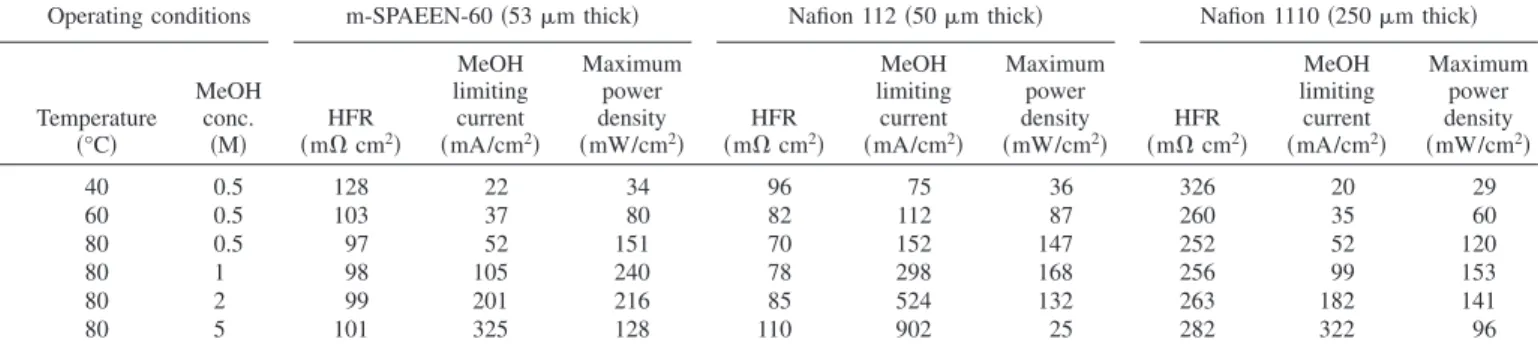
Table II reports the observed HFR, methanol limiting current densities, and maximum power densities of three different
mem-branes: m-SPAEEN-60 共53 m thick兲, Nafion 共50 m thick兲, and Nafion 共250 m thick兲, as a function of cell temperature and metha-nol feed concentration. From the data presented in Fig. 2 the supe-rior properties of m-SPAEEN can be directly compared. While thin Nafion 共50 m thick兲 has slightly lower HFR 共except at high metha-nol concentration兲, methametha-nol crossover rates are substantially higher. Thick Nafion 共250 m thick兲 has essentially identical methanol crossover rates, with substantially increased HFR. Some variations of these properties exist with temperature and concentration, but the trends are fairly consistent. Finally, maximum power density, while not the ideal indicator of performance because efficiency is not properly weighted, shows that m-SPAEEN-60 compares favorably to that of Nafion.
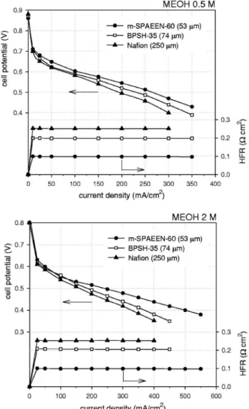
Figure 3 shows the cell performance of the MEAs using m-SPAEEN-60, BPSH-35, and Nafion at methanol feed concentra-tions of 0.5 and 2 M. As would have been expected from the data in Fig. 2 and Table II, the performance of the MEA using m-SPAEEN-60 was superior to that of the MEAs using BPSH-35 and Nafion, with BPSH-35 being slightly improved compared to Nafion. For example, the current density of the MEA using m-SPAEEN-60 at 0.5 V and 0.5 M methanol was 265 mA/cm2,
whereas the current densities of the MEAs using BPSH-35 and Nafion were 230 and 195 mA/cm2. At 2 M methanol, open-circuit
potential and mass-transport limitations for all MEAs decreased but the performance trend remained remarkably similar to that at 0.5 M methanol. As these membrane thicknesses were chosen based on equivalent methanol crossover limiting currents, it is reasonable to suggest that performance differences could be largely attributed to changes in ohmic losses reflected in the HFR values, also shown in Fig. 3.
IR-corrected polarization curves, which comprise the measured cell voltage plus estimated ohmic losses 共measured HFR multiplied by cell current density兲 vs cell current density, are shown in Fig. 4. These data allow cell performance to be compared independently of ohmic losses and show that indeed the performance differences shown in Fig. 3 are primarily the result of ohmic losses, as IR correction results in nearly equivalent performance from all three samples. The remaining small differences in performance can be attributed to differences in methanol crossover rates as a function of current density 共due to issues such as membrane tortuosity and electro-osmotic drag兲, membrane-electrode interfacial variability, or other issues such as sample-to-sample variability of the electrodes of each specific sample or water transport issues through the mem-branes and flooding within the cathode backing. Of particular inter-est is membrane-electrode interfacial resistance, which has already been reported for BPSH-35 and Nafion under these operating con-ditions and is known to be small.7 These results suggest the m-SPAEEN-60 membrane-electrode interface resistance is also likely small.
Along similar lines, a previous study indicated that MEAs using alternative membranes and Nafion-bonded electrodes often suffered from membrane-electrode interfacial failure during life testing, with-Table II. HFR, methanol limiting current densities, and maximum power densities of three different membranes under various operating conditions: m-SPAEEN-60 (53 m thick), Nafion (50 m thick), and Nafion (250 m thick).
Operating conditions m-SPAEEN-60 共53 m thick兲 Nafion 112 共50 m thick兲 Nafion 1110 共250 m thick兲
Temperature 共°C兲 MeOH conc. 共M兲 HFR 共m⍀ cm2兲 MeOH limiting current 共mA/cm2兲 Maximum power density 共mW/cm2兲 HFR 共m⍀ cm2兲 MeOH limiting current 共mA/cm2兲 Maximum power density 共mW/cm2兲 HFR 共m⍀ cm2兲 MeOH limiting current 共mA/cm2兲 Maximum power density 共mW/cm2兲 40 0.5 128 22 34 96 75 36 326 20 29 60 0.5 103 37 80 82 112 87 260 35 60 80 0.5 97 52 151 70 152 147 252 52 120 80 1 98 105 240 78 298 168 256 99 153 80 2 99 201 216 85 524 132 263 182 141 80 5 101 325 128 110 902 25 282 322 96
B24 Journal of The Electrochemical Society, 155 共1兲 B21-B26 共2008兲
out any discernable chemical degradation.10,22,24The interfacial fail-ure was correlated with an increasing HFR and performance loss after 100 h. In order to verify the interfacial stability of the MEA using m-SPAEEN-60, an extended life test 共⬎100 h兲 was con-ducted. Figure 5 shows that the MEA using the m-SPAEEN-60 had stable HFR and a moderate current density loss 共approximately 40 mA/cm2兲 comparable to that of a Nafion MEA under the same
operating conditions 共with much higher performance throughout the life test兲.10The current density loss is thought to be primarily attrib-utable to platinum oxidation at the high cathode potential and is largely reversible. These results indicate that the interfacial compat-ibility of m-SPAEEN-60 is likely good using Nafion-bonded elec-trodes. These results clearly indicate the advantages of nitrile co-polymers in DMFC operation.
Conclusion
MEAs using a nitrile copolymer 共m-SPAEEN-60兲 have been demonstrated with significantly improved performance in DMFC compared to the MEAs using sulfonated polysulfone analogs 共BP-SHs兲 and industrial standard Nafion membranes under optimized conditions. The nitrile copolymers have relatively low WU allowing relatively high ion concentrations in the hydrated polymer matrix. This increased hydrated acid concentration offers more effective proton conduction while providing improved mechanical stability.
The nitrile copolymer was found to be stable with Nafion-bonded electrodes in the practical window for DMFC operation. Further development of the nitrile copolymer electrolytes for H2/air fuel
cells is being investigated and will be reported in the near future. Figure 3.DMFC performance of m-SPAEEN-60, BPSH-35, and Nafion at
0.5 and 2 M methanol feed concentration 共cell temperature: 80°C兲.
Figure 4.IR-corrected polarization curves of m-SPAEEN-60, BPSH-35, and Nafion at 0.5 and 2 M methanol feed concentration 共cell temperature: 80°C兲.
Figure 5.Current density and HFR changes of the MEA using m-SPAEEN 60 共cell temperature: 80°C, 0.5 M methanol, electronic load: constant 0.5 V, cathode humidification: 90°C兲.
Acknowledgments
The polysulfone copolymers tested in this study were kindly sup-plied by the research group of Professor James McGrath 共Virginia Polytechnic and State University兲. The collaboration is under the International Partnership on the Hydrogen Economy 共IPHE兲. The work 共NRCC No. 49123兲 conducted at the National Research Coun-cil of Canada was partially supported by the Technology and Inno-vation Fuel Cell Horizontal Program. The work conducted at the Los Alamos National Laboratory was supported by the U.S. Department of Energy Office of Hydrogen, Fuel Cells and Infrastructure Tech-nologies.
Los Alamos National Laboratory assisted in meeting the publication costs of this article.
References
1. M. A. Hickner, H. Ghassemi, Y. S. Kim, B. R. Einsla, and J. E. McGrath, Chem. Rev. (Washington, D.C.), 104, 4587 共2004兲.
2. B. Yang and A. Manthiram, Electrochem. Solid-State Lett., 6, A229 共2003兲. 3. K. Miyatake, H. Zhou, T. Matsuo, H. Uchida, and M. Watanabe, Macromolecules,
37, 4961 共2004兲.
4. W. L. Harrison, M. A. Hickner, Y. S. Kim, and J. E. McGrath, Fuel Cells, 5, 201 共2005兲.
5. Y. Z. Fu and A. Manthiram, J. Power Sources, 157, 222 共2006兲.
6. Y. S. Kim and B. S. Pivovar, Abstract 1215, The Electrochemical Society Meeting Abstracts, Vol. 2005-2, Los Angeles, CA, Oct 16-21, 2005.
7. B. S. Pivovar and Y. S. Kim, J. Electrochem. Soc., 154, B739 共2007兲. 8. M. J. Sumner, W. L. Harrison, R. M. Weyers, Y. S. Kim, J. E. McGrath, J. S. Riffle,
A. Brink, and M. H. Brink, J. Membr. Sci., 239, 199 共2004兲.
9. Y. S. Kim, M. J. Summer, W. L. Harrison, J. S. Riffle, and J. E. McGrath, J. Electrochem. Soc., 151, A2150 共2004兲.
10. Y. S. Kim and B. S. Pivovar, in 2006 Fuel Cell Seminar, Honolulu, HI, Nov 13-17, 2006.
11. Y. Gao, G. P. Robertson, M. D. Guiver, S. D. Mikhailenko, X. Li, and S. Kaliagu-ine, Macromolecules, 38, 3237 共2005兲.
12. Y. Gao, G. P. Robertson, M. D. Guiver, S. D. Mikhailenko, X. Li, and S. Kaliagu-ine, Polymer, 47, 808 共2006兲.
13. Y. Gao, G. P. Robertson, D. S. Kim, M. D. Guiver, S. D. Mikhailenko, X. Li, and S. Kaliaguine, Macromolecules, 40, 1512 共2007兲.
14. F. Wang, M. A. Hickner, Y. S. Kim, T. A. Zawodzinski, and J. E. McGrath, J. Membr. Sci., 197, 387 共2002兲.
15. Y. S. Kim, F. Wang, M. A. Hickner, S. McCartney, Y. T. Hong, W. L. Harrison, T. A. Zawodzinski, and J. E. McGrath, J. Polym. Sci., Part B: Polym. Phys., 41, 2816 共2003兲.
16. X. Ren, T. E. Springer, and S. Gottesfeld, J. Electrochem. Soc., 147, 92 共2000兲. 17. X. Ren, T. E. Springer, T. A. Zawodzinski, and S. Gottesfeld, J. Electrochem. Soc.,
147, 466 共2000兲.
18. Y. S. Kim, B. R. Einsla, M. Sankir, W. L. Harrison, and B. S. Pivovar, Polymer, 47, 4026 共2006兲.
19. S. Saha and H. Hamaguchi, J. Phys. Chem. B, 110, 2777 共2006兲.
20. Y. S. Kim and B. S. Pivovar, in Advances in Fuel Cells, Chap. 4, T. S. Zhao, Editor, Elsevier, Oxford, U.K. 共2007兲.
21. S. M. J. Zaidi, S. D. Mikhailenko, G. P. Robertson, M. D. Guiver, and S. Kaliagu-ine, J. Membr. Sci., 173, 17 共2000兲.
22. Y. S. Kim, J. E. McGrath, and B. S. Pivovar, Abstract 1471, The Electrochemical Society Meeting Abstracts, Vol. 2004-1, San Antonio, TX, May 9-13, 2004. 23. B. S. Pivovar, Y. X. Wang, and E. L. Cussler, J. Membr. Sci., 154, 155 共1999兲. 24. K. Miyatake, Y. Chikashige, E. Higuchi, and M. Watanabe, J. Am. Chem. Soc.,
129, 3879 共2007兲.
B26 Journal of The Electrochemical Society, 155 共1兲 B21-B26 共2008兲