Publisher’s version / Version de l'éditeur:
IEEE Transactions on Systems, Man, and Cybernetics, Part A: Systems And
Humans, PP, 99, pp. 1-12, 2012-05-01
READ THESE TERMS AND CONDITIONS CAREFULLY BEFORE USING THIS WEBSITE. https://nrc-publications.canada.ca/eng/copyright
Vous avez des questions? Nous pouvons vous aider. Pour communiquer directement avec un auteur, consultez la première page de la revue dans laquelle son article a été publié afin de trouver ses coordonnées. Si vous n’arrivez pas à les repérer, communiquez avec nous à [email protected].
Questions? Contact the NRC Publications Archive team at
[email protected]. If you wish to email the authors directly, please see the first page of the publication for their contact information.
Archives des publications du CNRC
This publication could be one of several versions: author’s original, accepted manuscript or the publisher’s version. / La version de cette publication peut être l’une des suivantes : la version prépublication de l’auteur, la version acceptée du manuscrit ou la version de l’éditeur.
For the publisher’s version, please access the DOI link below./ Pour consulter la version de l’éditeur, utilisez le lien DOI ci-dessous.
https://doi.org/10.1109/TSMCA.2012.2190138
Access and use of this website and the material on it are subject to the Terms and Conditions set forth at
Ontology fusion in high-level-architecture-based collaborative
engineering environments
Sun, Hongbo; Fan, Wenhui; Shen, Weiming; Xiao, Tianyuan
https://publications-cnrc.canada.ca/fra/droits
L’accès à ce site Web et l’utilisation de son contenu sont assujettis aux conditions présentées dans le site LISEZ CES CONDITIONS ATTENTIVEMENT AVANT D’UTILISER CE SITE WEB.
NRC Publications Record / Notice d'Archives des publications de CNRC:
https://nrc-publications.canada.ca/eng/view/object/?id=17ce76dc-5f37-49c4-8418-64eff96f74da https://publications-cnrc.canada.ca/fra/voir/objet/?id=17ce76dc-5f37-49c4-8418-64eff96f74da
Ontology Fusion in HLA-based Collaborative
Engineering Environments
Hongbo Sun
1,2, Member, IEEE, Wenhui Fan
2, Weiming Shen
1, Senior Member, IEEE, and Tianyuan Xiao
2 1Centre for Computer-assisted Construction Technologies, National Research Council, London, Ontario N6G 4X8, Canada2National CIMS Engineering Research Centre, Tsinghua University, Beijing 100084, China
Abstract—In HLA (High Level Architecture)-based distributed
heterogeneous collaborative engineering environments (CEEs), the construction of FOM (Federation Object Model) files is time consuming. This paper presents an ontology fusion approach aiming at establishing a common understanding in such collaborative environments. The proposed approach has three steps: ontology mapping, ontology alignment, and ontology merging. Ontology mapping employs a top-down approach to explore all bridge relations between two terms from different ontologies based on bridge axioms and deduction rules. Ontology alignment adopts a bottom-up approach to discover implicit bridge relations between two terms from different domain ontologies based on equivalent inference. Ontology merging generates a new collaboration ontology from discovered equivalent bridge relations. It adopts an axiom-based ontology fusion strategy, and takes heavy-weighted ontologies into consideration. It can find all the explicit and derived inter-ontology relations. In a typical collaborative engineering environment, the proposed approach has a great potential to improve the efficiency of preparation for HLA-based collaborative engineering processes, reduce the work load for adaptive adjustment of existing platforms, and enhance the reusability and flexibility of collaborative engineering environments. A case study has been conducted to validate the feasibility of the proposed approach.
Index Terms—Collaborative Engineering Environments,
Product Development, HLA - High Level Architecture, Ontology.
I. INTRODUCTION
n increasingly saturated markets, innovation and product development are essential conditions for the sale of products. Adopting collaborative engineering makes full use of several independent product development systems, and enhances their abilities at the same time. But as a matter of fact, collaborative engineering environments (CEEs) are complicated and comprise various computer-aided engineering (CAE) systems for collaborative design, simulation, and optimization. It involves processes like CAD modeling, simulation and
optimization, requires data and information like CAD digital models, CAE analysis and optimization results [1,2]. When several independent systems need to be integrated, common understanding among these systems is always a challenge.
High-level architecture (HLA) is a general purpose architecture for distributed computer simulation systems. It early development was sponsored by US Defense Modeling and Simulation Office. In 2000, it was adopted by IEEE as an international standard IEEE 1516 [3]. In its definition, federation is a named set of federate applications and a common Federation Object Model (FOM) that are used as a whole to achieve some specific objectives.
Since federates exist within a federation in the form of data abstraction, federated integration keeps well the independency of its participants. This kind of integration is more suitable for and is widely used in distributed and loosely coupled simulation integration. The owner of each participant does not need to worry about exposing too much private information. The federation only defines the interesting domains for given objectives and the rules of inter operations. It is a real loosely-coupled integration solution. Within a federation, subsystems collaborate in an indirect way so that the context of interoperation can be taken into consideration.
Nowadays more and more simulation functions have been added into collaborative product development [ 4]. The design of product can be deemed as a multi-step process in which a set of design goals and requirements are transformed into a functional system. Simulation functions help these systems fulfill their design goals and add to their potential values.
When simulation is added into a collaborative product development environment, there always exist several subsystems in the same environment with independent design goals. These subsystems may follow different design or management rules in their respective engineering fields [5].
In an HLA-based CEE, FED (Federation Execution Description) files describe the data and information exchange standard of a given simulation. They are essential to common understanding among collaborative systems. Within these files, the construction of FOM (Federation Object Model) needs multidisciplinary
I
Manuscript received October 20, 2010. Corresponding author: H. Sun (e-mail:[email protected]).
professional knowledge and technologies [6]. It is always time consuming and expensive.
Fortunately, ontology in knowledge engineering is the semantic basis of communication among domain entities. It is applicable to automatic reasoning, knowledge representation and reuse [ 7 ].Ontology-based approaches have been used to resolve the problem of heterogeneous data and information integration [8,9]. The target of this research is to explore a new FOM construction method which takes full advantage of ontology technologies.
From the viewpoint of reasoning ability, ontology can be briefly classified into two categories: light-weighted ontology and heavy-weighted ontology. Light-weighted ontology does not have the ability of reasoning. It is in fact a well-organized vocabulary. While heavy-weighted ontology has reasoning abilities, such as first-order predicate. It usually includes axiom or rule definitions for reasoning use. In this paper, a semi-automatic construction method of FOM files is proposed. Because it builds collaboration ontology from exchanging data ontologies of subsystems, and explores new bridge relations, it is deemed as a heavy-weighted ontology fusion algorithm. The rest of the paper is organized as follows. Section 2 reviews the related literature and analyses the requirements of this application problem. Section 3 discusses the theoretical foundations of the proposed method. Section 4 describes the algorithms supporting the proposed method. Three algorithms are introduced in this paper: ontology mapping, ontology alignment, and ontology merging. Section 5 depicts a typical collaborative engineering environment involving three systems to demonstrate the applicability of the proposed method. Section 6 provides conclusions and a further research plan concerning this research topic. A brief complexity analysis is also included in this section.
II. RELATED WORK
Although the target of this research is to develop a new FOM construction method in order to take full advantage of ontology technologies,this task is far from just applying existing ontology technologies into CEEs. The semi-automatic construction of FOMs can be considered as an ontology integration problem. Ontology
integration is the consequence of ontology
heterogeneousness (syntax heterogeneousness and
non-syntax heterogeneousness [9]). Ontology
heterogeneousness can be classified into four layers: representation, terminology, conceptualization, and semantics. In the representation layer, different representation forms are used, and the representation differences can be resolved by formalization. In the terminology layer, different terms are adopted, and the term differences can be resolved by term mapping. In the conceptualization layer, ontology theory always takes effect here. And the problems of semantics layer are hard to resolve [ 10 ]. When it comes to CEE, because collaboration participants adopt the same ontology construction tools and language, there is no difference in
representation at all. However, because of
multidisciplinary-coupled resolutions, regional
distribution of organizations, and various participants, heterogeneousness on the terminology, conceptualization and semantics layers cannot be ignored. That leads to several challenges in applying ontology technologies to CEE:
There is no well-established domain ontology to use [11].
Every subsystem is totally equal in position. There is no kernel subsystem. The merging order of capability ontologies should not influence the final merging results. A meta-structure should be designed to support separated domain laws and bridge relations.
There are significant differences among knowledge representation methods among the subsystems according to a different series of domain laws [12, 7]. These differences cannot be easily eliminated by means of existing ontology technologies. So bridge relations (the relations between related concepts from different representation systems) need to be preset by domain experts. Therefore, the light-weighted ontology approach is not applicable here.
All the factors mentioned above bring difficulties when applying existing methods to this problem. Most well-known ontology integration tools are not applicable here, including PROMPT [12], OntoMerge [13], MAFRA [14], GLUE [15] and OntoMap [16]. Some of them are built on literal-based similarity computing methods (e.g., OntoMerge, PROMPT, ONION, and Anchor-PROMPT), while others are too simple and weak in their description abilities (e.g., OntoMap). Some are instances-based merging (e.g., GLUE); others only adopt bridge axioms. There are also some methods that only take terms and structures of light-weighted ontologies into consideration [ 17 ]. When it comes to ontology construction, although formal concept analysis (FCA) [ 18 ] can be successfully applied to ontology construction, in the procedure of ontology fusion it is not convenient to use. If this method is adopted, the formal background must be recomputed before ontology merging. This computation brings too much work to CEE, and the computation of multidisciplinary formal backgrounds is difficult.
The main idea presented in this paper is to take full advantage of formalization to automatically discover implicit and explicit bridge relations among term pairs of different ontologies; then to establish the union of the equivalent term pairs as the collaborative ontology; and, at the same time, construct a well-defined meta-ontology in order to facilitate interoperations among independent subsystems. The process of building the output collaborative ontology from independent domain ontologies is called CEE ontology fusion.
The main challenges in ontology fusion include instances and concepts confusion, top concepts correspondences,
modeling habits differences, synonyms, and coding formats [9]. In an HLA-based collaborative engineering environment, the instances are created by restrict definitions of exchange information format. The instances are not confused with concepts. The foundation of this method is not literal semantic distance, so the problem of using similar words has no effect here. Since the data types used are defined in meta-ontology, the coding format is unique. Because the top concept is the given product, there is no doubt that the top concept is unique. In the scope of one collaboration project, collaboration ontologies are built in the same way by the same group of people, so there are no differences in modeling habits. Lastly, no matter what approach is adopted, synonym problems always need to be addressed by domain experts.
III. THEORETICAL FOUNDATION
Can we use ontology as a common understanding media for different disciplinary systems? Theoretically speaking, we can. Because, on one hand, the objective of CEE at one time is unique; every established model is describing some aspects of the same thing. On the other hand, the theory of concept lattice (Galois lattice) [19] provides solid ground for this method.
A. Definitions
Because the algebraic system defined on the concept set of CEE and the partial order relations of these concepts have the same upper bound and lower bound, it can be deemed as a concept lattice [20]. The common understanding models of CEE have a common source, a given product model, and any model involved is specialized in some aspects. They also share a common meta-data, binary stream, and any datum collaboration required is a given parse of a binary fragment. That is to say, the partial order relations such as part-of or inherit-from have a common ancestor, the product (⊤), and all the products have a common ancestor, Thing. Also the minimum original concept (⊥) defined under these partial orders is binary characters; and it is also the public descendants of these concepts. Based on this, the paper defines related concepts as follows:
Definition 1: CEE ontology
O ∷= (C, H , R , H , M, R , A)
CEE ontology O is defined as a seven tuple. C denotes a collaboration concept set of CEE. H defines a set of partial orders on concept setC. They are inheritance relations among the concepts involved. The concept sets and the inheritance relations form a directed acyclic graph (DAG) which source is the given model of collaborative product and whose sink is a binary fragment. R denotes a set of non-inherited partial order relations on concept set C, and these partial order relations correspond to concept attributes. H defines inherited relations on the partial order relation set R . M is a series of collaborative product meta-ontology concepts that give a series of inheritable instances of R . R denotes a set of partial order relations under M; they describe the relations among elements in the meta-ontology set, and they are also the basis for collaborative product ontology reasoning. A defines a set of axioms among the ontology concept set and meta-ontology relation set and they provide the major premises of CEE ontology reasoning.
Definition 2: CEE ontology fusion
fuse ∷= SET ⇀ O,
(∀c, c ∈ O → ∃f , f , f ⇔ f , f ∈ O ,
f ∈ O ,, O ⊂ SET , O ⊂ SET :fuse(f , f , SET ) = c )
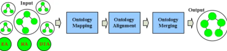
CEE ontology fusion is a partial order mapping from an ontology set of CEE to one ontology (as Fig. 1 shows). Because the fused ontology is for collaboration, only more than one ontology (representing the exchange information needed by a subsystem) employs the same concept, it is useful for future use. To any term c in the resultant ontology, it can find a corresponding term f in one ontology O which can be found in the prepared ontology set. At the same time, to use the term f there must be an equivalent term f in another ontology O of the prepared ontology set. Even the term is unique in different ontologies, it will appears in the fused ontology in a different name (with prefix of the original ontology). The only results of ontology fusion can be one ontology or null.
Fig.1. Collaborative engineering environments ontology fusion
The CEE ontology fusion procedure involves mapping from a set of ontologies {O , O , … , O } to one collaboration ontologyO . During this process, expert instructions work as the mechanism and meta-ontology MO controls the whole ontology fusion process.
The ontology fusion method introduced here includes three steps: mapping, alignment, and merging.
Definition 3: CEE ontology mapping
map ∷= E ⇀ E , (∀e ∈ O → ∃f ∈ O ∶
map(e, O , O ) = f ∨ map(e,O , O ) = ⊥). It is a partial order mapping based on vocabularyE of one ontology to vocabularyE of another ontology. The term e ∈ E may be concept, relation or instance. The mapping may be an equivalent relation, inherit relation or ownership. This mapping is not transmissible except that it describes equivalent relations. So, in the common sense, this mapping does not involve more than two heterogeneous ontologies.
Definition 4: CEE ontology alignment
align ∷= E × E → [0, 1],
align(e, f) = 1 ⇔ e = f: two concepts equal align(e,f) = 0 ⇔ e ≠ f: two concepts not equal The CEE ontology alignment function involves an equivalent mapping based on the concept vocabularyE of two different ontologies.
Definition 5: CEE ontology merging
merge ∷= SET ⇀ O,
It represents partial order mapping from an ontology set (SET ) of CEE to one ontology O. Any term e ∈ E in the output ontology, no matter whether it is a concept, a relation or an instance, it must have a corresponding term f in one ontology of the prepared merging ontology set.
Equivalent graph is a directed graph (may be an unconnected
one). It represents the equivalent relations of concepts in an ontology. In an ontology it is not possible for two concepts to be equal (they should be one concept with alias). Equivalent graph describes equivalent relations between one concept and a group of concepts or attributes. These equivalent relations can be classified into two categories: structure equivalent and description equivalent relations. The structure equivalent relation is comprised of a group of one-to-many equivalent relations defined on the partial order relations (inheritance) of the concepts or their attributes. There are two sub categories of structure equivalent relations: inheritance equivalent relation and division equivalent relation (see definitions below). The description equivalent relation is comprised of a group of one-to-many equivalent relations defined on the partial order relations (ownership) between one concept and a set of its attributes. One-to-one equivalent relations are included here, that means an attribute of the concept can be deemed as its identifier. What is more, the description equivalent relation has quantifier constraints.
Definition 6: inheritance equivalent relation
C ⇔ C ∩ C ∩ … ∩ C
The inheritance equivalent relation describes the relation of a given sub concept C that can be uniquely determined by a group of ancestor concepts {C , C , … , C } . To a given conceptC , there may be no inheritance equivalent relation concept set, or many equivalent relation concept sets.
Definition 7: division equivalent relation
C ⇔ C ∪ C ∪ … ∪ C
The division equivalent relation describes a group of complete divisions {C , C , … , C } of concept C . That is to say, any instance of C can find a corresponding instance of {C , C , … , C } . Specifically, the correspondence is not required to be unique here. To a given concept C , the division equivalent relation may or may not exist.
All of these equivalent relations mentioned above can be denoted by an m-in-arc with one degree (m is greater than 1), as shown in Fig. 2.
Fig. 2. Equivalent relations denotation
Definition 8: description equivalent relation
C ⇔ R . C ∩ R . C ∩ R . C … ∩ R . C ,
= ∀|∃|⅂| = | ≤ | ≥ , ∈ +, ∈ 1 … m
This gives the semantic equivalent relations between a concept C and a group of constrained attributes
{ R . C , R . C , R . C … , R . C } . The
constrained attribute group contains a set of attributes R . C constrained by description logic. C denotes a given concept. R denotes the partial order relation from C to C and represents the constraints. The constraints include quantifier constraints and numeric constraints. The universal quantifier constraint ∀ represents the relation value range and are all the instances of C ; the existential quantifier constraint ∃ means that relation has at least one corresponding value in instances of concept C ; the negative constraint ⅂ represents the fact that there is no correspondence of relation in C instances, and numeric constraint (= | ≤ | ≥ ) says relation owns a C instance number of = , ≤ or ≥ ; is a non-zero natural number. As a matter of fact, description equivalent relations and inheritance equivalent relations are often used together. Hence, descriptions equivalent relations are described as follows:
C ⇔ C ∩ R . C ∩ C … ∩ R . C
In an equivalent graph, the constrained attributes are denoted by an identifier on the m-in-arc, as shown in Fig. 3.
Fig. 3. Mixed Equivalent relation denotation
Equivalent and mutual exclusive graph is an enhanced
graph G′ based on equivalent graph G with the exclusive relations added (no longer a DAG). The mutually exclusive relation between concepts (C , C ) in CEE ontology is a symmetrical relation, and any instance of C and its sub concepts will not be the instance of C and its sub concepts. The equivalent and mutual exclusive graph denotes these relations by ↔ between C and C . One mutual exclusive relation may contain another one. In that case, two ancestor concepts of mutual exclusion imply descendant concepts mutual exclusion. This mutual exclusive relation is described as a trivial mutual exclusive relation.
Structure graph is a graphical representation of inheritance
relations H in a CEE ontology O ∷= (C, H , R , H , M, R , A). It is a DAG with only one source, and it denotes the inheritance relations among concepts.
Definition 9: equivalent relation bridge
C( )⇔ C( )
An equivalent relation bridge describes the equivalent relation between one term C( )in ontology O and another term C( )of a different ontology O . It presents itself in the form of a term pair (C( ), C( )). An equivalent relation bridge
is the main concept relation to be found in CEE ontology mapping and ontology alignment.
Domain equivalent bridge axioms refer to a group of semantic equivalent relations (C( ),C( )) from a concept set C( )of ontology O to a concept set C( )of ontology O , and
they are the foundation of inference or reasoning in CEE ontology mapping.
B. Mathematical Properties
This paper uses a ∧ a ∧ … a to denote the maximum lower bound of set {a , a , … , a } , and a ∨ a ∨ … a to represent its minimum upper bound.
Theorem 1: operations ∧, ∨ on CEE ontology concept lattice < , ≼> have properties as follows:
Idempotent law:
anya ∈ C, there exist a ∧ a = a, a ∨ a = a
Commutative law:
any a, b ∈ C, there exist a ∧ b = b ∧ a, a ∨ b = b ∨ a
Associative law:
any a, b, c ∈ C, there exist (a ∧ b) ∧ c = a ∧ (b ∧ c), (a ∨ b) ∨ c = a ∨ (b ∨ c)
Absorption law:
any a, b ∈ C, there exist a ∧ (a ∨ b) = a, a ∨ (a ∧ b) = a
It can be inferred from the above laws that the minimum upper bound and the maximum lower bound of any concept in CEE are themselves the concept. This is one of the most effective ways to align ontologies. When seeking the minimum upper bound and the maximum lower bound, the same operation is irrelevant to the order. The maximum lower bound of any concept with its ancestors is itself, and the minimum upper bound of any concept with its descendant is also itself.
Theorem 2: suppose < , ≼> is a concept lattice of given CEE ontology, ≽ is the reverse of relation ≼ . Any
, , , ∈ , there exist reflexivity: a ≼ a; a ≽ a anti-symmetry: a ≼ b and b ≼ a ⇒ a = b; a ≽ b and b ≽ a ⇒ a = b transitivity: a ≼ b and b ≼ c ⇒ a ≼ c; a ≽ b and b ≽ c ⇒ a ≽ c a ∧ b ≼ a; a ∨ b ≽ a; a ∧ b ≼ b; a ∨ b ≽ b c ≼ a and c ≼ b ⇒ c ≼ a ∧ b; c ≽ a and c ≽ b ⇒ c ≽ a ∨ b a ≼ b ⇒ a ∧ b = a ⇒ a ∨ b = b a ≼ b and c ≼ d ⇒ a ∧ c ≼ b ∧ d; a ≼ b and c ≼ d ⇒ a ∨ c ≼ b ∨ d rank preservation: a ≼ b ⇒ a ∧ c ≼ b ∧ c; a ≼ b ⇒ a ∨ c ≼ b ∨ c distribution inequality: a ∨ (b ∧ c ) ≼ (a ∨ b) ∧ (a ∨ c) ; a ∧ (b ∨ c ) ≽ (a ∧ b) ∨ (a ∧ c) norm inequality: a ≼ c ⇒ a ∨ (b ∧ c) ≼ (a ∨ b) ∧ c It can be easily inferred from Theorem 2 that the concept lattice of CEE consists of two abelian monoids with the same basic elements. The theorems above are an important source of basic axioms required by CEE ontology reasoning.
IV. ONTOLOGY FUSION ALGORITHM
As Fig. 4 shows, the main parts of ontology fusion include three algorithms: ontology mapping, ontology alignment and ontology merging.
Fig. 4. CEE ontology fusion framework
The purpose of ontology mapping is to mark definite equivalent relations and mutual exclusive relations of any term pair from two different ontologies in a collaborative ontology set. These relations are defined at the semantic level, and they can only be acquired by axioms (universal axioms, user defined axioms and data-type transformation
axioms) or deductions from these axioms. The
overlapping relations will be inferred and confirmed by the experts in the next step. Different from Quick Ontology Matching (QOM, ontology mapping is a part of ontology matching) which is based on literal semantic distance, this paper introduces an equivalent (mutual exclusive) graph-based domain axiom mapping algorithm.
Because (semi)automatic ontology alignment is a key issue of interoperation among ontologies [21], equivalent relations among terms should be discovered before interoperations as many as possible. The objective of ontology alignment is to infer all the equivalent relations of term pairs in which two terms are from different ontologies. Because the ontology may not be constructed in a sufficiently complete way, this procedure needs domain expert instructions.
CEE collaboration ontology merging is an important basis for collaboration among several ontologies. It corresponds to the procedure of negotiations to form a collaborative FOM among several Simulation Object Models (SOMs) in an HLA framework. This paper introduces an equivalent structure and a concept equivalent, bridge-based CEE ontology merging algorithm. The main task is to reorganize the equivalent terms which are found in the procedure of ontology alignment and ontology mapping, and then form the collaboration ontology, Federation ONtology (FON, the same as FOM in HLA).
The first step of ontology fusion is ontology mapping. This creates a bridge equivalent concept pair list and the bridge mutual exclusive concept pair list of a given ontology set, based on domain axioms. It can be described by algorithm 1.
Algorithm 1. Ontology_mapping({O }, DA)
DA domain axiom set
Output: EC bridge equivalent concept pair list
IC bridge mutual exclusive concept pair list
1 foreach(O ,O ) in {O } do
2 EC ← {(C( ),C( ))}
// find domain equivalent bridge axiom from DA
3 IC ← ∅
/*Extract equivalent (mutual exclusive) graphs */
4 G ← Equivalent(Mutual_Exclusive)_Relation_Travel(O )
5 G ← Equivalent(Mutual_Exclusive)_Relation_Travel(O )
/*Simplify equivalent (mutual exclusive) graphs by deleting trivial equivalent (mutual exclusive) relations (Thing, data type equivalent, trivial mutual exclusive relations and independent concept nodes)*/
6 G ← Simplify(G )
7 G ← Simplify(G )
/*According to {(C( ),C( ))}, mark {C( )} of G , and mark {C( )} in G , iteratively delete un-marked concepts of zero in-degree and their m-out-arc */
8 G′ ← Bridge_simplify(G )
9 G′ ← Bridge_simplify(G )
/*Inferring bridge equivalent relations, only equivalent graphs of G′ and G′ , G′ and G′ , are used here and all the discussions below are all based upon structure equivalent relations*/
10 foreach unmarked concept C in G′ do
11 if(∃ one-one bridge equivalent relation between ancestor concepts of
C and any concept of G′ , C ) then
12 EC← EC + (C , C )
//duplicate elements eliminated
13 elseif(∃ one-one bridge equivalent relation between ancestor
concepts of C and any concept of G′ , C , and the attributes, constraints, partial order relations between concept and its attributes are also equal, the concepts in constraint path also have corresponding equivalent bridge concepts.) then
14 EC← EC + (C , C ) 15 end if
16 end
/*Inferring bridge mutual exclusive relations*/
17 foreach (C( ),C( )) in {(C( ), C( )), I ∈ (i, j)} of G or G do
18 foreach equivalent concept of C( ), C( Ĩ)in EC do
19 IC← IC ∪ {(C( )× C( Ĩ))}
//According to the structure graph G of ontology
//O {C( )|G } is concept C( )and all of its descendents, the //same as {C( Ĩ)|G
Ĩ} .
20 end
21 foreach equivalent concept of C( ), C( Ĩ)in EC do
22 IC← IC ∪ {(C( )× C( ))}
23 end 24 end 25 end 26 return EC, IC
This algorithm adopts a knowledge representation and top-down inferring mechanism, based on equivalent (mutual exclusive) graphs and structure graphs. Its inferring ability is determined by the completeness of the domain equivalent bridge axioms. Compared with most mapping methods used to date, the main advantage of this algorithm is that most of the description features of heavy-weight ontology are taken into consideration, and this algorithm can find all the explicit and derived bridge relations.
The second step of ontology fusion is ontology alignment, which is developed to search implied bridge relations. After confirmation by the domain experts, these bridge relations are added into EC for further use.
Algorithm 2. Ontology_alignment({O }, EC, IC, DTA)
Input: { } candidate mapping ontology set
EC bridge equivalent concept pair list IC bridge mutual exclusive concept pair list DTA equivalent data type axiom set
Output: EC
1 foreach(O ,O ) in {O } do //Extract structure graphs
2 G ← Travel(O )
3 G ← Travel(O )
4 {(SC( ),SC( ))} ← O × O
// Cartesian product of concept set in O and O
/* According to mutual exclusive bridge relations simplify {(SC( ),SC( ))} */
5 if(∃{(IC( ),IC( Ĩ))} in IC and IC( )≡ SC( )) then
//{IC( )|G } is concept IC( )and all of its descendants //according to the structure graph G of O , the same as //{IC( Ĩ)|G
Ĩ} .
6 {(R C( ),R C( ))} ← {(SC( ),SC( ))} − {(IC( )
× IC( Ĩ))} 7 end if
/*According to equivalent bridge relations simplify {(R C( ),R C( ))} */
8 if(∃{(EC( ),EC(Ĩ))} in EC and EC( )≡ R C( )) then
//{EC( )|G } is concept EC( )and all its ancestors according //to the structure graph G of O , the same as {EC( Ĩ)|G
Ĩ}
9 {(R C( ),R C( ))} ←
{(R C( ),R C( ))} − {(IC( )) × (IC( Ĩ)) }
10 end if
/*Inferring equivalent bridge relations.*/
11 {(R C( ),R C( ))} ← {(R C( ),R C( ))}
12 foreach(R C( ),R C( Ĩ)) in {(R C( ),R C( ))} do
13 if(data type construction is different according to data type meta
class definition of meta ontology) then
//the difference of data type construction include data type unit
//number inconsistency and data type inheritable
14 {(R C( ),R C( ))} =
{(R C( ),R C( ))} − (R C( ),R C( Ĩ))
15 end if 16 end
17 {(R C( ),R C( ))} ←Confirmed({(R C( ),R C( ))})
// domain experts confirmation 18 end
19 return EC ← EC ∪ {(R C( ),R C( )), i < j}
This algorithm is defined on the structure graph-based knowledge representation and an attribute set comparison-based bottom-up inferring mechanism. The inferring capability relies on the comparison ability between attribute sets. The output of ontology alignment algorithms are term relations; a set of term pairs in different ontologies. This paper proposes the heuristic information-based (attributes equal), semi-automatic, bottom-up ontology alignment method. Because of heuristic information involved, the algorithm has a risk of making wrong judgments, so it needs a domain expert to confirm the candidate-equivalent bridge relations. It can reach the active upper bound of implicit equivalent bridge relations through searching, which greatly enhances the ability of CEE and remarkably reduces manpower. But ontology alignment does not generate new ontologies; it only establishes a mapping set to support interoperations among ontologies, so ontology merging is used here to generate new ontology, based on the existing ones.
In a typical CEE system, there are always two or more subsystems. As mentioned above, the concept lattice of CEE consists of two abelian monoids. So the final collaboration ontology can be constructed by one-one integration in turns.
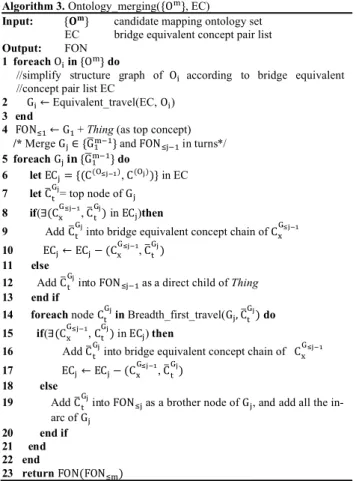
Algorithm 3. Ontology_merging({O }, EC)
Input: { } candidate mapping ontology set
EC bridge equivalent concept pair list
Output: FON
1 foreachO in {O } do
//simplify structure graph of O according to bridge equivalent //concept pair list EC
2 G ← Equivalent_travel(EC, O )
3 end
4 FON ← G + Thing (as top concept)
/* Merge G ∈ {G } and FON in turns*/
5 foreach G {G } do
6 let EC = {(C( ),C( ))} in EC
7 let C = top node of G 8 if(∃(C ,C ) in EC )then
9 AddC into bridge equivalent concept chain of C
10 EC ← EC − (C ,C )
11 else
12 AddC into FON as a direct child of Thing
13 end if
14 foreach node C in Breadth_first_travel(G , C ) do
15 if(∃(C ,C ) in EC ) then
16 AddC into bridge equivalent concept chain of C
17 EC ← EC − (C ,C )
18 else
19 AddC into FON as a brother node of G , and add all the in-arc of G
20 end if 21 end 22 end
23 return FON(FON )
This algorithm is defined on the equivalent structure graph-based knowledge representation and an attribute group comparison-based merging mechanism. Compared with light-weight ontology merging which is based only on structure and terms, the main advantage of this algorithm is that, when merging ontologies, the heuristic information, such as the equivalent structure graph and semantic equivalence of the attribute, is also taken into consideration. The efficiency and accuracy of ontology merging have been greatly improved.
V. CASE STUDY
A typical CEE unit can be described as having three main parts (Fig. 5): scene creator, localization server and decision
support system. The scene creator generates scenes for collaboration jobs. The localization server keeps tracking important entities and the decision support system makes the final decision or suggestions about a future collaboration step. The collaboration information among these three independent systems lies in the scene provided by Scene Creator, localization information supported by Localization Server and instructions from the Decision Support System. In this paper, the Localization Server is supposed to be a real time tracking system, so it does not need any instructions.
Fig. 5. A typical collaborative engineering environments unit
Before an HLA-based collaborative job started, the exchange data formats of each subsystem should be claimed first as SOM files (Fig. 6). Then domain experts sit together to negotiate about the general collaborative data formats. This processes is time consuming and expensive. Then a general collaborative data format will be defined and a FOM file (looks similar to SOM files) will come into being. After these have been finished, every subsystem changes its interfaces according to the new data exchange format. Finally the collaborative job can be performed. When the collaborative job changes, this process (negotiation and changing interfaces) repeats again.
When the proposed method is adopted, the workload for negotiation and interface changing is significantly reduced, though some preparations still need to be done. First a meta-ontology is built to provide templates of capability description ontologies, data type definitions and axioms. Then capability description ontologies of these systems are constructed separately according to the ability and requirements of the related engineering domains.
Fig. 6. SOM File of Localization System
Meta-ontology (MO) is the ontology which stores the fundamental knowledge of inferences. It contains object templates, basic transformation data types and necessary general axioms. This approach is compatible with the definition of HLA OMT (Object Model Template) object classes and interaction classes.
Scene creator adopted here is a Building Information Management System. All the files which can be seen in an IFC (Industry Foundation Classes) viewer are deemed as an IFC building. Every element of IFC building has a unique UUID (Unique Universal IDentifier). IFC building has five sub categories: Building Element Proxy, IFC Building Elements, Single Storey Building, Multi-Storey Building and Space. Building Element Proxy is the monitor of building Elements, such as hydrometer and thermostat. Building Element is a part of Building. Single Storey Building is a Building that only owns one Storey. Multi-Storey Building is a building that has at least two floors. Space is somewhere which is isolated. IFC Building Elements include Basic wall, Furnishing Elements, Opening, Roof and Stair. Basic wall with openings is called Wall. Opening includes Window, Door and Door Entry. Furnishing Elements include Fixed Furniture and Movable Furniture. The Movable furniture is the target of localization system.
The Decision Support System adopted here is a Facility Maintenance Management System. The concepts involved here
include Point, Building Description, Building Element and Building. Point exists in some space, when it has special meaning it becomes Physical location. Building description includes attributes of Buildings, such as Location and Map. Location can be specialized into Building Location, Level Location, and Physical Location. In this system, Assets are deemed as Building Elements. Among these Assets, assets with locations are looked as Trackable Assets. Building is a closed space in the management scope, which can be specialized into Frame, Level or Space and Room. The main objective of this system is asset tracking and maintenance.
Localization system adopted here is called AeroScout. The main concepts used in this system are Tag, Map, Coordinate, Asset, Corrective Action and Building. Tag can be divided into Active tag and Inactive tag according to the tracking state. Map can be specialized into Building Location, Level Location, Area Location and Zone Location or Physical Location. Physical Location is also a subclass of Coordinate. Asset can be classified into Arranged Asset and Live Asset. Arranged Asset belongs to some Department. Live Asset is a movable Asset. Among Live Assets, Trackable Assets are binding with Active Tags. Corrective Actions include Event and Internal Event, such as Invoking and Moving. Corresponding to the map, Building can also be specialized into Level, Area and Zone. The main targets of tracking are Active Assets.
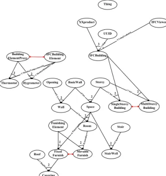
The final preparation task is to abstract graphs from these ontologies. Because these systems are too complicated for a demonstration, only part of the concepts and relations are described in this paper. The bridge relation graphs are shown in Fig. 7, 8, 9 and structure graphs in Fig. 10,11,12.
Thing
XXproduct IFCViewer
IFCBuilding UUID
Space SingleStoreyBuilding
MultiStorey Building IFCBuilding Element Building ElementProxy Hygrometer Thermostat Storey Room StairWell BasicWall Stair Roof Opening Funishing Element Wall Fixed Furnish Movable Furnish Covering 3 2 2 2 2 2 2 2 =1 Monito
rTemperatu reOf =1 Mon itorH umidi tyOf =1 B indW ith $ Usin gToolk itOf >1 has =1 has 2 4 has 2 1 has 2 2
Fig. 7. Scene Creator Equivalent (mutual exclusive) Graph Demo
In Scene Creator Equivalent (mutual exclusive) Graph Demo, there are 12 equivalent relations and three mutual exclusive relations.
IFC Building ⇔ product ∩ (= 1 ℎ . UUID) ∩
(∃ . IFCViewer)
SingleStorey Building ⇔ IFC Building ∩ (= 1 ℎ . Storey) MultiStorey Building ⇔ IFC Building ∩
(> 1 ℎ . Storey) Thermostat ⇔ Building ElementProxy ∩
(= 1 . IFC Building Element)
Hygrometer ⇔ Building ElementProxy ∩
(= 1 . IFC Building Element)
Wall ⇔ Basic Wall ∩ (> 1 ℎ . Opening) Space ⇔ Storey ∩ (≥ 4 ℎ . Basic Wall) Room ⇔ Space ∩ (≥ 1 ℎ . Wall) StairWell ⇔ Space ∩ (≥ 1 ℎ . Stair) Fixed Furniture ⇔ Furnishing Element ∩
(= 1 . Space)
Movable Furniture ⇔ Furnishing Element ∩
(= 1 . Room)
Covering ⇔ Fixed Furniture ∩ (= 1 . Roof) Single Storey Building ↔ Multi − Storey Building Fixed Furniture ↔ Movable Furniture
Building Element Proxy ↔ IFC Building Element
Fig. 8. Decision Support System Equivalent (mutual exclusive) Graph Demo
ha
s
³1
h
as
Fig. 9. Localization System Equivalent (mutual exclusive) Graph Demo
Similarly, in Decision Support System Equivalent (mutual exclusive) Graph Demo, there are seven equivalent relations and one mutual exclusive relation. In Localization System Equivalent (mutual exclusive) Graph Demo, there are 10 equivalent relations and two mutual exclusive relations.
Thing
XXproduct IFCViewer
IFCBuilding UUID
Space SingleStorey
Building MultiStoreyBuilding IFCBuilding
Element Building
ElementProxy
Hygrometer Thermostat BasicWall FunishingElement Opening Roof Stair Storey Room StairWell
Wall FurnishFixed MovableFurnish
Covering
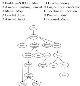
Let S denote the scene creator, L represent the localization system and D stand for the decision support system. The bridge equivalent relations given by domain experts are as follows, and no new mutual exclusive bridge relation is inferred.
D.Building=S.IFCBuilding D.Level=S.Storey D.Asset=S.FinishingElement D.LogicalLocation=S.Room D.Map=L.Map D.Location=L.Location D.Level=L.Level D.Point=L.Point D.Asset=L.Asset D.Room=L.Zone
Fig. 11. Decision Support System Structure Graph Demo
By the ontology mapping algorithm mentioned above, new bridge equivalent relations are inferred as follows:
D.TrackableAsset=S.MovableFurnish D.PhysicalLocation=L.PhysicalLocation D.BuildingLocation=L.BuildingLocation D.LevelLocation=L.LevelLocation D.LogicalLocation=L.ZoneLocation D.TrackableAsset=L.LiveAsset
Fig. 12. Localization System Structure Graph Demo
The candidate equivalent bridge relations inferred by the ontology alignment algorithm are all denied by the domain experts, and no candidate mutual exclusive bridge relations are generated from this algorithm.
After ontology merging, the collaboration ontology is reached as shown in Fig. 13.
By means of the ontology fusion algorithms described above, the collaboration ontology is easily established. What the domain experts need to do is to give well known equivalent (mutual exclusive) bridge relations and to judge the inferred candidate relations, which significantly reduces the workload of domain experts and improves the efficiency of collaboration preparations. At the same time, because ontologies have expandability and equivalent (mutual exclusive) bridge relations are also stored in meta-ontology for future use, the ability of resources reuse is also remarkably enhanced in the CEEs.
Fig. 13. Output Collaboration Ontology Demo
VI. CONCLUSION
In HLA-based CEEs, it is difficult to establish a collaborative system, but it is even more difficult to adaptively adjust interface codes of existing systems and to negotiate among multidisciplinary domains [22]. This paper proposes a semi-automatic ontology fusion method to establish a collaborative ontology as a media in HLA-based CEEs, which is constructed by several independent subsystems. These subsystems may be working in different domains. The main part of this method includes three algorithms: ontology mapping, ontology alignment and ontology merging.
Based on complexity analysis, this approach may not be the best choice. Because this approach is based on bridge axioms and equivalent relations, it is not easy to compare with other ontology integration methods. For the same reason, OAEI (Ontology Alignment Evaluation Initiative) is not applicable here. Here is a brief complexity comparison. Let n denote the concept number in the ontology, and l represent the length of DA (Domain Axiom set). When integrating two ontologies, the complexities of existing algorithms are: NOM - Naive Ontology MappingO(n ∙ log n) , PROMPT O(n ∙ log n) , Anchor-PROMPT O(n ∙ log n), GLUE O(n ) and QOM -Quick Ontology Mapping O(n ∙ log n) [21]. While the complexity of our ontology mapping algorithm is O(n ∙ l), and the complexity of our ontology alignment algorithm is O(n ).
Despite its complexity, it enjoys several remarkable advantages which are more suitable for HLA-based multidisciplinary collaborations:
This method has firm theoretical foundations and starts from strict definitions.
It reduces the workload of domain experts to prepare collaborations among independent engineering domains by automatic inference and deduction. For the same reason, it improves the efficiency in the preparation of future collaborations.
Different from most other ontology integration methods using literature distance, this method employs axioms, bridge axioms, equality rules and attribute set equality conditions as the basis for reasoning.
The proposed algorithms can find all the explicit and derived bridge relations.
Since ontology is used in this method, the reuse of resources and the expandability of existing systems are greatly enhanced.
The construction method of collaborative ontology also helps to accumulate knowledge and furthermore to build relatively complete models of the same objective from different aspects.
The applicability of the proposed method has been demonstrated through a case study. More efforts are still required in order to improve the proposed method for real industrial applications.
ACKNOWLEDGMENT
This work was partially supported by Chinese National High-Tech Research and Development Program (863 Program, Grant No. 2009AA110302) and Chinese Nature Science Foundation (Grant No. 60874066).
REFERENCES
[1] W. Fan, W. Wang and T. Xiao, “Multidisciplinary Collaboration Simulation Optimization Platform for complex product design”, Proceedings of the 2nd International Conference on Pervasive Computing and Applications, 2007 ( ICPCA 2007). Birmingham, UK, 174 -178, Jul. 2007.
[2] H. Sun, T. Xiao and S. Tang, “Research on Federation-Based Pragmatic Integration Framework, Proceedings of 2009 World Congress on Computer Science and Information Engineering (CSIE 2009)”. Los Angeles/Anaheim, USA, Apr. 2009.
[3] Simulation Interoperability Standards Committee (SISC) of the IEEE Computer Society, “IEEE Standard for Modeling and Simulation(M&S) High Level Architecture (HLA)-Framework and Rules”, The Institute of Electrical and Electronics Engineers, Inc. New York, 2000.
[4] Y. Xu, T. Xiao, C. Liang and L. Zhang, “Federated integration of networked manufacturing service platforms”, Advanced Engineering Informatics. vol. 22, 317-327, Jul. 2008.
[5] S. Tang, T. Xiao and W. Fan, “A collaborative platform for complex product design with an extended HLA integration architecture”. Simulation Modelling Practice and Theory. vol. 18(8),1048-1068, Sep. 2010.
[6] IEEE Computer Society, “IEEE standard for modeling and simulation (M&S) high level architecture (HLA)-object model template (OMT) specification(IEEE Std 1516.2- 2000)”, NewYork: The Institute of Electrical and Engineers, 2001.
[7] W. Zhou, Z. Liu, and H. Chen, “A Survey of the Research about Both FCA and Ontology”, Computer Science, China, 33(2) 8-12,2006. [8] J. Yu, and Y. Dang, “Review on Ontology Integration, Computer
Science”, China, 35 (7) 9-14, 2008.
[9] F. Fürst and F. Trichet, “Axiom-based ontology matching: a method and an experiment”, research report, Mar. 2005.
[10] C. Bock, X. Zha, H. Suh and J. Lee, “Ontological product modeling for collaborative design”, Advanced Engineering Informatics. in Press, 2010.
[11] A. Umar and A. Zordan, “Enterprise Ontologies for Planning and Integration of Business: A Pragmatic Approach”, IEEE Transactions on Engineering Management, 56 (2) 352-371, May. 2009.
[12] N. F. Noy and M. A. Musen, “The PROMPT Suite: Interactive Tools For Ontology Merging And Mapping”, International Journal of Human-Computer Studies, 59 (6), 983-1024, Dec. 2003.
[13] D. Dou, D. McDermott, and P. Qi, “Ontology Translation on the Semantic Web”, Journal on data semantics II, 3360 (2005) 35-57, 2005. [14] A. Maedche, B. Motik, N. Silva and R. Volz, “MAFRA —An Ontology
MApping FRAmework in the Context of the Semantic Web”, In Workshop on Ontology Transformation at ECAI - 2002, Lyon, France, July 2002.
[15] A. Doan, J. Madhavan, P. Domingos, and A. Halevy, “Learning to map between ontologies on the semantic web”, Proceedings of the 11th international conference on World Wide Web, Honolulu, Hawaii, USA, 662-673, 2002.
[16] H. Schnurr and J. Angele, “Do not use this gear with a switching lever!Automotive industry experience with semantic guides”, 4th International semantic web conference, Galway, IRLANDE, 3729 (2005) 1029-1040, 2005.
[17] Y. Huang, H. Zhou, J. Li, L. Tan, and Z. Li, “Survey of Ontology Mapping Approaches”, Computer Engineering and Applications, China, 18 (2005) 27-29, 2005.
[18] B. Ganter, G. Stumme, R. Wille, “Formal concept analysis: foundations and applications”, Springer-Verlag Berlin Heidelberg, Germany, 2005. [19] R. Wille, “Concept lattices and conceptual knowledge systems”.
Computers & Mathematics with Applications, 23 (1992) 493-515, 1992. [20] K. Qu, J. Liang, J. Wang and Z. Shi, “The algebraic properties of
Concept Lattice”, Journal of Systems Science and Information, 2(2) 271-277, 2004.
[21] M. Ehrig and S. Staab, “QOM - Quick Ontology Mapping, Proceedings of the International Semantic Web Conference(ISWC)”, Hiroshima, Japan, 683-697, Nov. 2004.
[22] B. Li, X. Chai, G. Xiong, W. Zhu, C. Quan, H. Zhang and X. Wang, “Research and Primary Practice on Virtual Prototyping Engineering of Complex Product”, Journal of System Simulation, 14 (3) 336-341, 2002.
H.Sun received his Bachelor degree in Information Science from Beijing
Institute of Technology, China in 1998, his Master’s degree in Software Engineering from Tsinghua University, China in 2005, and his PhD degree in Control Science and Engineering from Tsinghua University in 2011.
He is currently a Postdoctoral Researcher at National CIMS ERC, Tsinghua University, Beijing, China. He was visiting researcher at National Research Council Canada from November 2009 to November 2010. Between 2005 and 2006, he served as a Software Engineer at National CIMS ERC, Tsinghua University, Beijing, China. From 1998 to 2002, he was an Assistant Professor at Shenyang Institute of Technology, Liaoning, China. His research interests include system integration, artificial intelligence, algorithms, large-scale simulation and e-commerce.