Received: 13 February 2003 Accepted: 28 April 2003
Published online: 20 August 2003 © Springer-Verlag 2003
Abstract During the past 5 years balanced steady-state free precession (SSFP) has become increasingly im-portant for diagnostic and functional imaging. Balanced SSFP is charac-terized by two unique features: it of-fers a very high signal-to noise ratio and a T2/T1-weighted image con-trast. This article focuses on the physical principles, on the signal for-mation, and on the resulting proper-ties of balanced SSFP. Mechanisms for contrast modification, recent clinical application, and potential ex-tensions of this technique are dis-cussed.
Keywords Rapid imaging · Contrast modification · Transient phase Klaus Scheffler
Stefan Lehnhardt
Principles and applications of balanced SSFP
techniques
Introduction
Although formally described in 1958 by Carr [2] bal-anced steady-state free precession (SSFP) has only be-come feasible (and popular) during the past 3–5 years. At the same time several new acronyms for balanced SSFP have been created such as TrueFISP, balanced FFE, and FIESTA. In several publications and confer-ence abstracts balanced SSFP is just called SSFP to em-phasize that the magnetization is acquired during the steady state. This is very confusing and wrong, since all rapid gradient-echo sequences are SSFP sequences, even the radio-frequency-spoiled fast low-angle shot (FLASH; SPGR, T1-FFE) sequence. Different steady states are established for different gradient switching patterns. The most important types of SSFP sequences are the FLASH (GRASS, FAST, FFE), the CE-FAST (PSIF, T2-FFE), and balanced SSFP sequence. This arti-cle gives an overview of the basic physical principles of balanced SSFP, a detailed description of contrast- and signal-to-noise mechanisms, and potential image
arti-facts. Different possibilities to modify the generic con-trast of balanced SSFP are described in the second part, followed by a short overview of current clinical applica-tions, and examples of possible extensions.
Physical principles of balanced SSFP
Each type of gradient-echo (GE) sequence consists of a train of excitation pulses that are separated by a constant time interval (TR). The acquisition and the spatial Fouri-er encoding of the gradient echo is pFouri-erformed between consecutive excitation pulses by means of switched gra-dient pulses along read, phase, and slice direction. The effect of excitation and gradient pulses on a single mag-netization vector can be described by the Bloch equation [1]. As depicted in Fig. 1, an excitation pulse corre-sponds to a rotation of the magnetization vector by a cer-tain angle α(the flip angle), whereas dephasing (induced by gradient pulses or other field inhomogeneities) is equivalent to a rotation around the z-axis. The amount of K. Scheffler (
✉
)Department of Medical Radiology, MR-Physics,
University Hospital,
Petersgraben 4, 4031 Basel, Switzerland e-mail: [email protected] Tel.: +41-61-2655557
Fax: +41-61-2655351 S. Lehnhardt
Department of Diagnostic Radiology, University Hospital of Freiburg, Hugstetterstrasse 55, 79106 Freiburg, Germany
dephasing θ within TR depends on the spatial position and on the gradient strength and duration. In addition to these rotations, T1 and T2 relaxation occurs during TR. T1 relaxation results in a small increase of the longitudi-nal component of the magnetization vector, and T2 re-laxation gives a shortening of the transverse part by a factor of exp(-TR/T2). After one TR, the next excitation pulse acts on the modified magnetization, and the pro-cess of rotation and relaxation is repeated again and again. It can be shown that under certain conditions (constant α, θ, and TR) a steady state of the magnetiza-tion will be established after several TR periods (~5T1/TR). This situation is called steady-state free pre-cession (SSFP) and was formally first described by Carr [2]. All types of currently used, fast GE sequences are SSFP techniques. The difference between the various types of GE sequences, such as FLASH, FAST, GRASS, FFE, CE-FAST, and PSIF, is a different gradient switch-ing patter applied between consecutive excitation pulses. Different gradient time courses produce different (spa-tially dependent) dephasings θwithin TR, which finally results in different types of steady states, and more im-portantly, in different image contrasts.
Balanced SSFP is a special type of SSFP sequence where the gradient-induced dephasing within TR is ex-actly zero [3]. In other words, within TR each applied gradient pulse is compensated by a gradient pulse with opposite polarity. This makes the pictorial description of the evolving magnetization from excitation pulse to exci-tation pulse very simple and concise. The overall magne-tization consists of a single magnemagne-tization vector that is not spatially dephased, as for non-balanced SSFP se-quences.
Evolution of the magnetization within TR
In a first step we analyzed the motion of the magnetiza-tion within one TR period for the balanced SSFP
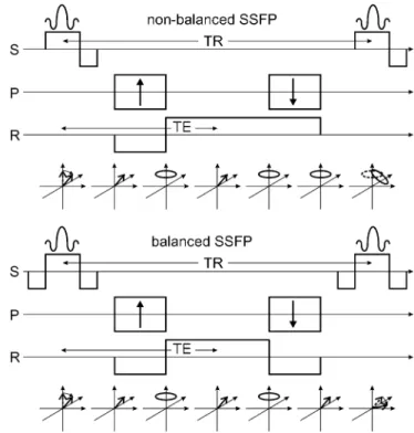
(b-SSFP) and non-balanced SSFP (nb-SSFP, such as FLASH or GRASS) sequence (Fig. 2). The first excita-tion pulse turns the equilibrium magnetizaexcita-tion by an an-gle of α into the transverse plane. The gradient applied in z-direction during the excitation pulse is used for slice selection (S). Conventional slice selective excitation pulses (sinc or Gaussian shaped) applied together with a slice selection gradient produce a linear dephasing of the magnetization along slice select direction, and a second slice selection gradient with opposite polarity has to be applied to refocus the magnetization; therefore, for both b-SSFP and nb-SSFP sequences the resulting magnetiza-tion after the slice selecmagnetiza-tion gradient is a single, rephased magnetization vector tilted by an angle of α away from the z-axis. The following gradients are used for frequen-cy (read gradient) and phase encoding (P and R axis).
For simplicity we assume that we are just encoding the center line of k-space, which means that the phase-encoding gradient is zero. Then, the negative lobe of the read gradient induces a dephasing of the previously aligned magnetization. The dephasing is compensated by the positive gradient lobe, and neglecting other field in-homogeneities, the magnetization will be rephased at TE to form again a single magnetization vector (the gradient echo). Until this point (TE) b-SSFP and nb-SSFP are still equivalent. After TE, the magnetization will be de-Fig. 1 Evolution of the magnetization within one TR cycle. The
excitation pulse rotates the magnetization by an angle of αfrom the initial z-position towards the transverse plane. The phase of the excitation pulse is along the y-axis. Dephasing due to switched gradients or field inhomogeneities corresponds to a certain rota-tion around the z-axis. Relaxarota-tion during TR leads to a decrease of the transverse component (T2) and an increase of the z-component (T1)
Fig. 2 Evolution of the magnetization within one TR period for a
SSFP (refocused FLASH) and a b-SSFP sequence. For nb-SSFP, the readout gradient is not balanced resulting in dephased magnetization after one TR period. For b-SSFP, all three gradient axes are refocused or balanced leading to a single magnetization vector at the end of TR
phased again by the read gradient. For b-SSFP this de-phasing is compensated with a negative read gradient lobe, resulting again in a fully refocused, single magneti-zation vector. The read gradient is not balanced for nb-SSFP, and the final magnetization is evenly distributed on a disk in the transversal plane. This is the main differ-ence between b-SSFP and nb-SSFP: the net transverse magnetization after one TR is zero for nb-SSFP; for b-SSFP the magnetization at the beginning of the TR in-terval (just after the excitation pulse) and at the end of the TR interval (just before the next excitation pulse) is nearly identical, except for some T1 and T2 relaxation effects.
The next excitation pulse thus acts on a single magne-tization vector. For nb-SSFP the second excitation pulse partially turns the disk of dephased magnetization into the transverse plane, and the dephasing within TR cre-ates an increasingly complicated pattern of dephased magnetization. These increasingly higher states of de-phased magnetization form a very interesting 3D pattern of dephased magnetization. The analysis and description of these states is actually much more complicated than the fully refocused magnetization of the b-SSFP se-quence. A pictorial description of rapid SSFP imaging is given by Scheffler [4].
The b-SSFP excitation pulse train
For reasons explained later, the b-SSFP excitation train consists of an initial α/2 preparation pulse followed by a train of alternating ±α excitation pulses [5]. The ±α pulses are separated by TR, whereas the time interval be-tween the α/2 preparation pulse and the first –αpulse is TR/2. Since we know that the switched gradient pulses between consecutive excitation pulses have no influence on the magnetization, it is very easy to analyze the mo-tion of the magnetizamo-tion during such an excitamo-tion pulse train. If we further neglect relaxation effects, the motion of the magnetization becomes a very simple oscillation around the z-axis, as shown in Fig. 3a. The initial α/2 pulse brings the magnetization immediately into its steady state position, and subsequent alternating ±α pulses produce the oscillation around the z-axis. The am-plitude of the echo signal is M0sin(α/2) which corre-sponds to the transverse part of the magnetization vector. A very similar behavior is observed if relaxation is in-cluded. As depicted in Fig. 3b (left), the magnetization vector still oscillates around the z-axis, but relaxation produces a certain damping of the magnetization. All magnetization vectors are aligned on a α/2 cone and the amplitude of their transverse part converges toward the steady sate. The resulting smooth decay of the transverse magnetization MTis shown in Fig. 3b (right). From these figures it is also clear that is very beneficial to start the excitation pulse train with an α/2 preparation pulse. This
preparation pulse aligns the magnetization onto the α/2 cone resulting in a smooth approach towards the steady sate. The same steady state will also be reached without the α/2 preparation pulse, as shown in Fig. 3c; however, the intense initial signal fluctuations would produce se-vere image artifacts and can thus not be used for signal acquisition.
Sensitivity of b-SSFP to off-resonance effects
Up to now, we have assumed that we have a perfect shim across the entire field of view (FOV), or equivalently, the absence of any dephasing of the magnetization be-tween excitation pulses. In typical applications the achievable field homogeneity is approximately 50 Hz for the brain, and 100–200 Hz for the abdomen at 1.5 T. A frequency offset ν (frequency difference between radio-frequency synthesizer of scanner and local precession frequency of the magnetization) results in a dephasing of θ=2πνTR within TR. This is, for example, 108° for TR=3 ms and ν=100 Hz. It is obvious that this additional dephasing leads to a modification of the resulting steady state, and hence to a certain deviation from the ideal os-Fig. 3 a Starting with an initial α/2 preparation pulse the magneti-zation describes a simple oscillation around the z-axis by means of alternating ±α excitation pulses. b If relaxation is included, a smooth damping of the oscillation can be observed towards a cer-tain, oscillating steady state. c The same steady state will be reached without α/2 preparation pulse, but the resulting initial fluctuations cannot be used for image acquisition
cillation around the z-axis (Fig. 3b). Fortunately, these deviations are relatively small (for small off-resonance frequencies). Figure 4a depicts the positions of the steady-state magnetization for increasingly higher dephasing θwithin TR (or higher off-resonance frequen-cies). Due to the off-resonance frequency, the magnetiza-tion performs a rotamagnetiza-tion around the z-axis by an angle of θ=2πνTR between alternation excitation pluses (top view, projection onto the transverse plane).
Interestingly, this dephasing starts at an angle of θ/2 away from the x-axis and ends at the position –θ/2. In other words, at the echo time TE=TR/2 the magnetiza-tion vector is exactly aligned along the x-axis, indepen-dent of the total dephasing θ. This refocusing mechanism is very similar to the spin-echo formation. The refocus-ing mechanism breaks down above some certain point of dephasing, leading to a nearly complete collapse of the steady-state signal. This threshold lies somewhat below θ=π and can be visualized by the amplitude-frequency profile of b-SSFP (Fig. 4b).
This profile gives the steady-state amplitude of b-SSFP as a function of some field inhomogeneity-induced dephasing θwithin TR [2]. It is a 2π-periodic profile that shows very sharp and significant signal drops at ±π. This specific signal profile as a very important consequence for b-SSFP imaging: the signal amplitude depends on the
local shim! For example, if we assume a variation of ±200 Hz across the FOV and a TR of 3 ms, we will have different dephasings between −216° and +216° at differ-ent spatial locations. This leads to the well-known band-ing artifacts, characterized by strong signal drops at re-gions where θ=±π or ν=±167 Hz for TR=3 ms. An ex-ample is shown in Fig. 4b (right). For banding-free im-aging the allowed range of different off-resonance fre-quencies has thus to be confined to approximately . From these calculations it is immediately clear that b-SSFP benefits from very short TR that allows covering a brought range of off-resonance frequencies. In other words, a short TR makes b-SSFP less sensitive to field inhomogeneities.
Contrast and signal-to-noise of b-SSFP
Besides potential image artifacts, the most important feature of an imaging sequence is its contrast. While the classical SE sequence either shows a T1- or a T2-weight-ed contrast (or proton-density-weightT2-weight-ed), rapid GE se-quences, including b-SSFP, exhibit a relatively compli-cated contrast that is composed (it is not just a product) of T1 and T2 contributions. The steady-state signal in-tensity of b-SSFP has already been shown in Fig. 4b for different off-resonance frequencies. On-resonance the re-sulting signal intensity is a function of T1, T2, TR, and flip angle α, and is given by
(1) with E1,2= e-TR/T1,2 , and M
0is the proton density [6, 7].
This equation can be simplified under the assumption that TR<<T1,T2(which is the case for most biological tis-sue at 1.5 T and a TR of 3–5 ms) [8]:
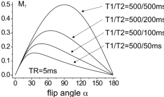
(2) Figure 5 shows the signal intensity of b-SSFP for differ-ent ratios of T1 and T2 as a function of the flip angle α. The optimal flip angle depends on T1 and T2 and is giv-en by
(3) which results in a signal amplitude of [8]:
(4) If T1 and T2 are similar (i.e. for CSF or fat) the optimal flip angle is around α=70–90°, and the maximum possi-ble signal approaches 50% of M0! This is a very remark-able feature of b-SSFP, and there exists no other type of sequence that is able to continuously acquire 50% of the Fig. 4 a The motion of magnetization (filled circles correspond to
the tip of the magnetization, projected onto the x–y plane) during one TR for different dephasings θ. For increasingly higher depha-sings θthe trajectory shows an increasingly higher deviation from the simple oscillation around z. The steady state breaks down for
θ=180°. b The steady-state signal amplitude of b-SSFP as a func-tion of the dephasing between TR. This profile is characterized by a brought plateu interrupted by sharp signal drops. The b-SSFP thus provides high signal amplitudes within some range of differ-ent off-resonance frequencies but shows a strong signal loss if de-phasing is near multiples of 2π. This leads to the well-known banding artefacts as shown right (arrows)
total available spin polarization M0! Based on its totally coherent steady-state magnetization, b-SSFP thus offers the highest possible signal-to-noise ratio (SNR) per unit time of all known sequences.
However, the contrast of b-SSFP is given by the ratio of T2 and T1, which is certainly not optimal for diagnos-tic purposes. A typical feature of the b-SSFP contrast is the very high signal intensity of liquids and fat (both have completely different T1 and T2 values, but a simi-lar ratio of T2 and T1; see Fig. 4b), which cannot be seen on purely T1- or T2-weighted sequences. A further example is shown in Fig. 6. The bottles are filled with water and different concentrations of a gadolinium-based contrast agent, resulting in T1 values between 100 and 1500 ms. For b-SSFP the signal intensities of different bottles are nearly identical since the contrast agent re-duces both T2 and T1 (the relaxivities R2 and R1 of the contrast agent are similar). A clearly T1-weighted con-trast can be observed for the radio-frequency-spoiled FLASH sequence.
For the sake of completeness it is noted that the echo amplitude MSSof b-SSFP is not additionally weighted by a factor of exp(-TE/T2*) as for the FLASH sequence. B-SSFP does not show the conventional T2* sensitivity as other nb-SSFP sequences. This can be explained by the fact that, within a certain range, field inhomogeneity-in-duced dephasing will be nearly completely refocused at TE=TR/2 leading to the formation of a spin echo rather than a gradient echo [9]. As already included in Eq. (1), the steady state signal MSSof b-SSFP is thus additionally weighted by exp(-TE/T2) which is equal to
(5)
Further contrast mechanisms
So far we have focused on the steady state contrast of b-SSFP. The signal intensity during the transition to the steady state, however, shows a remarkably different be-haviour. The duration of the transient phase is of the or-der of 50–500 excitation pulses, as shown in Fig. 3. It can be shown that the decay rate towards the steady state is a weighted average between a pure T1 and a pure T2 de-cay. For very small flip angles (α) the decay is mainly controlled by T1. High flip angles produce a faster decay towards the steady state. For α=180°, the signal decays exactly with T2 towards zero (MSS=0 for α=180°; see Eq. (1)). This case is actually very similar to a multi-spin-echo sequence such as rapid acquisition with relaxation enhancement (RARE): both sequence types start with a 90° excitation pulse followed after TR/2 by 180° refocus-ing pulses separated by TR (echo spacrefocus-ing for RARE).
Due to the relatively long duration of the transient phase of b-SSFP, the contrast of 2D images compared with 3D images is quite different, as shown in Fig. 7. The 2D image exhibits a mixed contrast between proton density and . The 3D image shows the pure steady-state contrast characterizedby a loss of contrast between grey and white matter, and an increased signal of fat and cerebrospinal fluid.
Inflow or motion effects can further modify the con-trast of b-SSFP, as shown for two examples in Fig. 8. An especially high contrast between the transient signal of inflowing blood and the steady-state signal of muscle (which is low due to a low T2/T1 ratio) can be observed, which makes b-SSFP very useful for cardiac imaging. No inflow enhancement can be created in 3D applica-tions as shown right (with fat saturation), resulting in a similar steady-state contrast of blood and other tissues. Fig. 5 Steady state signal intensity as a function of the applied
flip angle. For similar T1 and T2 the signal approaches 50% of M0 for a flip angle of 90°
Fig. 6 The b-SSFP and nb-SSFP (T1-weighted FLASH) image of
bottles filled with water and different concentrations of a conven-tional gadolinium-based contrast agent. Since reduction of T1 and T2 is similar the ratio T2/T1 is nearly independent of the concen-tration of the contrast agent leading to comparable signal intensi-ties for b-SSFP. A clear T1 contrast can be observed for T1-weighted FLASH
Implementation of b-SSFP
Balanced SSFP requires short TR in the range of 3–6 ms to minimize banding artefacts. This is the main reason why b-SSFP, although proposed in 1986 by Oppelt et al. [3], has only become feasible (and popular) during the past 3–5 years. With the design of very fast gradient am-plifiers it was possible to reduce the time to switch all relevant gradients needed for echo encoding to a few milliseconds. During the past years each manufacturer invented its own acronym for b-SSFP, for example, TrueFISP (Siemens, originally call FISP by Oppelt et al. [3]), balanced FFE (Philips), or FIESTA (GE). A slow version of b-SSFP, called CISS (constructive interfer-ence in steady state), with TR of approximately 15–20 ms was introduced approximately 10 years ago. The CISS consists of two consecutive 3D b-SSFP runs. The first b-SSFP part uses alternating ±αexcitation puls-es, and the second b-SSFP run is performed with con-stant α pulses. As a result, two image sets are acquired that show mutually shifted banding artefacts. A maxi-mum intensity projection (or a more sophisticated algo-rithm) between these two data sets gives the banding-free CISS image.
The minimum possible TR for b-SSFP is comparable to the TR of rapid GE sequences that are used for CE
MRA; However, b-SSFP requires relatively high flip an-gles between 50–80° to generate the highest possible sig-nal. This can easily exceed the SAR limits, especially in ultra-high field applications beyond 1.5 T. A possibility to reduce SAR is the use of optimized slice excitation pulses, or to apply varying flip angles during the excita-tion pulse train [10, 16].
Modification of the generic b-SSFP contrast:
magnetization preparation
The modification and optimization of the contrast of an imaging sequence with certain magnetization preparation techniques, such as inversion or fat saturation pulses, is a common method that has been widely applied in combi-nation with FLASH or RARE sequences [11, 12]. Typi-cal examples are the FLAIR or STIR sequence (combi-nation of inversion pulse with RARE-based acquisition block), or the MPRAGE sequence (inversion pulse and FLASH sequence). In the ideal case, the contrast of mag-netization-prepared sequences is exclusively generated by the preparation scheme, and the subsequent signal or image acquisition block is just used to detect the pre-pared magnetization; therefore, the acquisition block should not introduce an additional contrast to the already prepared magnetization, and, in terms of SNR, it should be as effective as possible. B-SSFP is thus ideally suited to read-out prepared magnetization.
Several approaches have already been proposed to modify the non-specific T2/T1-weigthed contrast of b-SSFP. The single-shot methods are comparable to the existing methods based on FLASH or RARE. The steady-state magnetization preparation techniques re-present conceptually new approaches that rely on the special magnetization trajectory of b-SSFP.
Single-shot magnetization preparation
The basic scheme of this preparation technique is shown in Fig. 9 [5, 13]. In principle, any known type of magne-tization preparation can be used to modify the b-SSFP signal. The use of inversion or saturation pulses has been proposed, for example, to enhance the contrast between grey and white matter, or to introduce T1-weighting. In-version-prepared b-SSFP can also be used for rapid T1 quantification as shown in Fig. 10. A further application to assess blood perfusion in the kidney based on arterial spin labelling is shown in Fig. 10. Labelling was achieved by selective inversion of the inflowing aortic blood [14]. Further possibilities to combine magnetiza-tion preparamagnetiza-tion with b-SSFP may include T2*, T2, or diffusion preparation, or a combination of them.
As for other magnetization-preparation techniques it is important to notice that the prepared contrast is par-Fig. 7 A 2D b-SSFP acquisition shows a transient contrast
com-pared with b the T2/T1-weighted steady-state contrast of 3D b-SSFP
Fig. 8 2D b-SSFP shows a inflow enhancement (the
time-of-flight effect) which cannot be observed in b 3D applications (right, with fat saturation)
tially modified by the b-SSFP contrast; however, if the time between preparation and encoding of the central k-space line is short (i.e. in segmented or centric reordered acquisitions) these deviations are relatively small. A more severe problem are initial signal fluctuations that may occur during the first 10–30 repetitions of the b-SSFP excitation train. As described previously, the initial α/2 preparation pulse separated by TR/2 from the first excitation pulse is used to stabilize the transient signal evolution [5]. This preparation scheme, however, partial-ly fails for off-resonance spins leading to similar signal oscillations as shown in Fig. 3c. This is a major problem especially for single-shot techniques, and several ap-proaches have been proposed to stabilize the initial, tran-sient phase. A very robust and simple method is to use linearly increasing flip angles for the first 5–15 excita-tion pulses [15]. A further possibility is to use the RARE excitation scheme based on a 90° excitation pulse and
180° refocusing pulses, followed by a train of decreasing flip angles towards the final flip angle of 50–70°. This technique is called transition into driven equilibrium (TIDE) and can also be use to modify the contrast of b-SSFP [16]. Further stabilization methods are based on preparation schemes that “catalyze” the required steady-state magnetization [17].
Steady-state magnetization-preparation techniques In contrast to single-shot techniques steady-state magne-tization preparation offers the possibility to incorporate virtually any contrast into a continuously running b-SSFP sequence [18]. This allows for a very efficient contrast modification, since signal acquisition is inter-rupted only for short periods. In order to maintain the high steady-state signal the periodic interruption of the b-SSFP excitation train with preparation pulses requires a dedicated preparation and non-preparation scheme, as shown in Fig. 11. Before preparation the excitation train is stopped with an α/2 non-preparation pulse that stores the steady-state magnetization in z-direction. After prep-aration, the stored z-magnetization is used again by means of the α/2 preparation pulse. This technique can be used for rapid, fat-saturated or T2-weighted b-SSFP imaging.
A further possibility to modify the contrast during the steady state is a continuous variation of the flip angles of the excitation pulses. This can be done either with the TIDE technique [16], or by using flip angles that depend on the distance between encoded space position and k-space centre [10]. A (non-linear) variation of the phase of the excitation pulses is able to create several-steady states that exhibit different frequency-amplitude re-sponse profiles. Selection or combination of different steady states can thus be used to generate spectral-selec-tive images [28, 29].
Clinical applications of balanced SSFP
From the previously described properties of b-SSFP it can be deduced that b-SSFP has limited application for conventional diagnostic imaging that is based on T1- or T2-weighted techniques; however, b-SSFP is a very fast Fig. 9 Basic principle of single-shot magnetization-prepared
b-SSFP. After preparation, b-SSFP is started with an α/2 preparation pulse
Fig. 10 a Series of b-SSFP images acquired after different
inver-sion times after a slice-selective inverinver-sion pulse. This series can be used to derive quantitative T1 maps, as shown right. b Selective inversion pulse along the descending aorta was applied as a mag-netic label for inflowing blood (arterial spin labelling). Subtraction of a non-labelled with a labelled acquisition gives the perfusion image of the kidneys (right)
Fig. 11 Principle of contrast modification during the steady state
of b-SSFP. The steady-state magnetization is stored in z-direction before magnetization praparation, and is recalled after preparation
imaging technique that shows a strong contrast between tissues with different rations of T2 and T1, for example, between blood and muscle (or myocardium), between fat and muscle, or between liquid compartments and sur-rounding tissue. B-SSFP is thus perfectly suited for mor-phological imaging such as cardiac or vessel imaging. The following examples give a short and non-compre-hensive overview of some current clinical applications of b-SSFP.
Cardiac imaging
The motion of the myocardium is conventionally observed with rapid, T1-weighted FLASH sequences [19]. The cine images can then be used to quantify parameters such ejec-tion fracejec-tion or ventricular mass. The b-SSFP offers a much higher contrast between muscle and blood than FLASH, which is beneficial for subsequent segmentation algorithms [20, 21]. Figure 12 shows a comparison between FLASH and b-SSFP. The high contrast of b-SSFP is produced both by the different ratio of T2 and T1 of blood and myocardi-um and by inflow effects. A second advantage of b-SSFP is its high SNR even for very short TR. A FLASH sequence with comparable TR and optimized Ernst flip angle exhibits a much lower SNR and contrast-to-noise ratio (CNR).
Angiography
The different T2/T1 ratios of blood and surrounding tis-sue are beneficial for angiografic imaging with b-SSFP; however, depending on the chosen imaging parameters, such as slice thickness and orientation, the observed con-trast is actually a mixture of the transient/steady state contrast of b-SSFP and signal-enhancing inflow effects, as depicted in Fig. 8. A major problem of b-SSFP-based angiography is the very intense fat signal that easily ex-ceeds the signal of inflowing blood. An efficient fat satu-ration is thus mandatory, especially for coronary arteries that are surrounded by fat [22]. Figure 13 shows three different angiography techniques that are based on b-SSFP acquisition. Imaging of the left anterior descend-ing (LAD) coronary artery was performed durdescend-ing free breathing using a navigator technique. The acquisition window was placed within the late diastole, and conven-tional fat saturation was use prior to b-SSFP acquisition (Fig. 13, left). A different approach was used for time-of-flight (TOF) imaging of the cerebral vessels, shown in Fig. 12 Comparison of FLASH and b-SSFP for cardiac imaging
Fig. 13a–c Comparison of different angiography techniques
based on b-SSFP. a Coronary artery imaging was performed dur-ing free breathdur-ing usdur-ing a navigator technique. The b-SSFP was applied for 160 ms during the late diastole preceded by a fat satu-ration pulse. b The TOF acquisition was measured without fat saturation. Background suppression was achieved by repetitive, slice-selective inversion pulses. c The use of inversion pulses and contrast agent can be used for contrast enhanced angiography, and offers a significantly higher contrast-to-noise ratio than con-ventional approaches
Fig. 13 (middle). The 3D b-SSFP acquisition block was continuously interrupted with a selective inversion pulse for every 1200 ms. As a result, the stationary tissue is nearly completely saturated while inflowing blood shows the full (transient) b-SSFP signal. This new approach of-fers a significant increase in CNR as compared with con-ventional 3D TOF techniques [23]; however, no fat satu-ration was applied for this preliminary application. A further technique that is based on the flow-sensitive phase evolution between excitation pulses was recently proposed for MR angiography [27]. Figure 13 (right) shows an example of contrast enhanced b-SSFP angiog-raphy that potentially offers an increase of CNR of up to 100% compared with FLASH-based techniques. The T1 and T2 values of blood during the first pass of a contrast agent are very similar (approximately 50–150 ms) result-ing in the highest possible b-SSFP signal of up to 50% of M0. The surrounding tissue was saturated by repetitively applied inversion/saturation pulses, which finally pro-duces an excellent contrast between vessel and back-ground. In this example additional fat saturation was ap-plied immediately before inversion/saturation [24].
T2-like applications
Balanced-SSFP is certainly not a T2-weighted sequence. Long T2 relaxation times produce high signal intensity, but short T2 times in combination with short T1 times might show the same signal intensity. For the diagnosis of diseas-es of the abdomen and the liver, the detection of hepatic le-sions, the demonstration of the bile duct system and the ex-act illustration of the vessels, especially in the pre-opera-tive planning, is essential [26]. The mixed contrast of b-SSFP is certainly not optimal for diagnosing hepatic
le-sions. Additionally susceptibility artifacts due to field inho-mogeneities and artifacts at tissue interfaces close to the gastrointestinal tract hamper the use of these sequences in the abdomen; therefore, so far there is no evidence for di-agnostic use in detection and characterization of hepatic le-sions with b-SSFP [30]. This thesis was underlined by a re-cent study which compared b-SSFP and half-Fourier sin-gle-shot turbo spin-echo (HASTE) in the liver. It was found that neither HASTE nor b-SSFP alone are sufficient for detection and characterization of hepatic lesions [31].
A clearer contrast can be achieved if compartments with long T2 are not surrounded by tissues with compa-rable T2/T1 ratios. Two examples are shown in Fig. 14. The liquid containing inner ear and cranial nerve is clearly separated from the background. This single 3D b-SSFP acquisition shows an identical contrast compared with the CISS technique, and offers a sub-millimetre res-olution within an acquisition time of several minutes.
Recently, hydro-MRI in patients with chronic inflam-matory disease of the small bowel (Crohn’s disease) has been introduced [32]. With the use of T2 HASTE se-quences and post-contrast images stenosis, small bowel wall changes and activity of the inflamed wall could be demonstrated. A promising approach of imaging the small bowel could be the use of 3D fat saturated b-SSFP sequences (Fig. 14, middle and right). A sufficient lumen opacification and an increased wall delineation with an improved wall conspicuity could be achieved, which is mainly caused by an improved tissue contrast. Extramu-ral complications can be detected with high diagnostic accuracy. With the use of ultrafast sequences the acquisi-tion time can be reduced, producing fewer moacquisi-tion arte-facts. By using 3D sequences during one breath-hold pe-riod the possibility of secondary reconstruction, e.g. maximum intensity projection and multiplanar recon-struction, is given [18]. A further (preliminary) field of application is the detection and segmentation of spinal nerve roots where the high signal of CSF offers a good separation to the surrounding tissue [25].
Fig. 14 a Conventional and fat-saturated 3D b-SSFP is used to
depict and separate tissues or compartments with long T2 relax-ation times. b Patient with Crohn’s disease and multiple stenosis.
c Patient with Crohn’s disease and inflammatory pseudotumor
Conclusion
Balanced SSFP offers the highest SNR per unit time of all other imaging sequences. For an optimized flip angle the resulting contrast is T2/T1-weighted. This type of mixed contrast has limited application for diagnostic im-aging, but is beneficial for functional or morphological
imaging such as cardiac imaging. Magnetization-prepa-ration techniques can be used to modify the b-SSFP con-trast for specific applications. Signal instabilities during the initial phase of the excitation train as well as reduc-tion of radio-frequency power deposireduc-tion can be achieved with dedicated schemes of varying flip angles of the excitation pulses.
References
1. Bloch F (1946) Nuclear induction. Phys Rev 70:460–474
2. Carr HY (1958) Steady-state free precession in nuclear magnetic reso-nance. Phys Rev 112:1693–1701 3. Oppelt A, Graumann R, Barfuss H,
Fischer H, Hartl W, Schajor W (1986) FISP: a new fast MRI sequence. Electromedica (Engl Ed) 54:15–18 4. Scheffler K (1999) A pictorial
descrip-tion of steady states in fast magnetic resonance imaging: concept. Magn Res 11:291–304
5. Deimling M, Heid O (1994) Magneti-zation prepared true FISP imaging. In: Proc Second Annual Meeting of the Society of Magnetic Resonance, San Francisco, p 495
6. Freeman R, Hill HDW (1971) Phase and intensity anomalities in Fourier transform NMR. J Magn Reson 4:366–383
7. Zur Y, Stokar S, Bendel P (1988) An analysis of fast imaging sequences with steady-state transverse magnetiza-tion refocusing. Magn Reson Med 6:17–193
8. Haacke EM, Brown RW, Thompson MR, Venkatesan R (1999) In: Magnetic resonance imaging: physical principles and sequence design. Mosby, St. Louis, chap. 18
9. Scheffler K. Hennig J (2003) Is TrueFISP a spin-echo or gradient-echo sequence? Magn Reson Med
49:395–397
10. Schaeffter T, Weiss S, Börnert P (2002) A SAR-reduced steady-state free precessing (SSFP) acquisition. Proc ISMRM, Honolulu, p 2351 11. Haase A (1990) Snapshot FLASH
MRI: applications to T1, T2, and chemical-shift imaging. Magn Reson Med 13:77–89
12. Norris D, Börnert P, Reese T, Leibfritz D (1992) On the application of ultra-fast RARE experiments. Magn Reson Med 27:142–164
13. Scheffler K, Hennig J (2001) T1 quantification with inversion recovery TrueFISP. Magn Reson Med
45:720–723
14. Scheffler K, Thiel T, Thesen S (2002) Assessment of perfusion with arterial spin labeling and TrueFISP. Proc ISMRM, Honolulu, p 628
15. Nishimura DG, Vasanawala SS (2000) Analysis and reduction of the transient response in SSFP imaging. Proc 8th Annual Meeting ISMRM, p 301 16. Hennig J, Speck O, Scheffler K (2002)
Optimization of the signal behavior in the transition to driven equilibrium in steady-state free precession sequences. Magn Reson Med 48:801–809 17. Hargreaves BA, Vasanawala SS, Pauly
JM, Nishimura DG (2001) Character-ization and reduction of the transient response in steady-state MR imaging. Magn Reson Med 46:149–158 18. Scheffler K, Heid O, Hennig J (2001)
Magnetization preparation during the steady state: 3D fat saturated TrueFISP. Magn Reson Med 45:1075–1080 19. Wagner S, Buser P, Auffermann W,
Holt WW, Wolfe CL, Higgins CB (1989) Cine magnetic resonance imaging: tomographic analysis of left ventricular function. Cardiol Clin 7:651–659
20. Barkhausen J, Ruehm SG, Goyen M, Buck T, Laub G, Debatin JF (2001) MR evaluation of ventricular function: true fast imaging with steady-state precession versus fast low-angle shot cine MR imaging: feasibility study. Radiology 219:264–269
21. Jung BA, Hennig J, Scheffler K (2002) Single-breathhold 3D-trueFISP cine cardiac imaging. Magn Reson Med 48:921–925
22. Deshpande VS, Shea SM, Laub G, Simonetti OP, Finn JP, Li D (2001) 3D magnetization-prepared TrueFISP: a new technique for imaging coronary arteries. Magn Reson Med 46:494–502
23. Leupold J,Hennig J, Scheffler K (2002) 3D time-of-flight MRI using inversion recovery TrueFISP. Proc ISMRM, Honolulu, p 138
24. Scheffler K, Winterer JT, Langer M, Hennig J (2002) Contrast-enhanced angiography using T1-weighted True-FISP. Proc ISMRM, Honolulu, p 139 25. Amartur SC, Wielopolski PA, Kormos
DW, Modic MT, Clampitt M (1991) Tissue segmentation for three-dimen-sional display of human spines. Med Phys 18:305–308
26. Lienemann A, Anthuber C, Baron A, Kohz P, Reiser M (1997) Dynamic MR colpocystorectography assessing pelvic-floor descent. Eur Radiol 7:1309–1317
27. Overall WR, Conolly SM, Nishimura DG, Hu BS (2002) Oscillating dual-equilibrium steady-state angiography. Magn Reson Med 47:513–522 28. Vasanawala SS, Pauly JM, Nishimura
DG (2000) Linear combination steady-state free precession MRI. Magn Reson Med 43:82–90
29. Hardy CJ, Dixon WT (2002) Steady-state free precession imaging with inherent fat suppression. Proc ISMRM, Honolulu, p 473 30. Petsch R, Helmberger T, Reiser M
(1999) New techniques and pulse sequences in MRI of the liver. Radio-loge 39:662–670
31. Herborn CU, Vogt F, Lauenstein TC, Goyen M, Debatin JF, Ruehm SG (2003) MRI of the liver: Can TrueFISP replace HASTE? J Magn Reson Med 17:190–196
32. Rieber A, Aschoff A, Brambs HJ (2000) MRI in the diagnosis of small bowel disease: use of positive and negative oral contrast media in combination with enteroclysis. Eur Radiol 10:1377–1382