Publisher’s version / Version de l'éditeur:
Vous avez des questions? Nous pouvons vous aider. Pour communiquer directement avec un auteur, consultez la première page de la revue dans laquelle son article a été publié afin de trouver ses coordonnées. Si vous n’arrivez pas à les repérer, communiquez avec nous à PublicationsArchive-ArchivesPublications@nrc-cnrc.gc.ca.
Questions? Contact the NRC Publications Archive team at
PublicationsArchive-ArchivesPublications@nrc-cnrc.gc.ca. If you wish to email the authors directly, please see the first page of the publication for their contact information.
https://publications-cnrc.canada.ca/fra/droits
L’accès à ce site Web et l’utilisation de son contenu sont assujettis aux conditions présentées dans le site LISEZ CES CONDITIONS ATTENTIVEMENT AVANT D’UTILISER CE SITE WEB.
Paper (National Research Council of Canada. Division of Building Research),
1985-05-01
READ THESE TERMS AND CONDITIONS CAREFULLY BEFORE USING THIS WEBSITE. https://nrc-publications.canada.ca/eng/copyright
NRC Publications Archive Record / Notice des Archives des publications du CNRC :
https://nrc-publications.canada.ca/eng/view/object/?id=171d0f8d-9b87-4956-b4dc-d7c89beab78a
https://publications-cnrc.canada.ca/fra/voir/objet/?id=171d0f8d-9b87-4956-b4dc-d7c89beab78a
NRC Publications Archive
Archives des publications du CNRC
This publication could be one of several versions: author’s original, accepted manuscript or the publisher’s version. / La version de cette publication peut être l’une des suivantes : la version prépublication de l’auteur, la version acceptée du manuscrit ou la version de l’éditeur.
For the publisher’s version, please access the DOI link below./ Pour consulter la version de l’éditeur, utilisez le lien DOI ci-dessous.
https://doi.org/10.4224/40001228
Access and use of this website and the material on it are subject to the Terms and Conditions set forth at
Performance of an elastoplastic model
Ser
1
TH1
N21d
Ino. 1272
c.2
BLDC
National Research
Conseil national
I
+
Council Canada
de recherches Canada
PERFORMANCE OF AN ELASTOPLASTIC MODEL
by
E. Evgin and Z. EisensteinReprinted from
Canadian Geotechnical Journal Vol. 22, No. 2, 1985
Pages 177-185
DBR Paper No. 1272
Division of Building Research
ANALYZED
Performance of an elastoplastic model
E. EVGINDivision of Building Research, National Research Council of Canada, Ottawa, Ont., Canada KIA OR6 AND
Z. EISENSTEIN
Department of Civil Engineering, University of Alberta, Edmonton, Alta., Canada T6G 2G7 Received January 27, 1983
Accepted January 7, 1985
Lade's elastoplastic work-hardening model for cohesionless soils has been used in a deformation analysis. Two passive earth pressure tests were utilized to compare analytical and experimental results. The load-deformation response and distribution of normal stresses acting on a fully instrumented wall were predicted, but a new interpretation of the work-hardening rule was necessary in order to use the model in the solution of boundary value problems. Measured and calculated values were generally in agreement. The results indicate that the model has the potential to produce reliable predictions of the behaviour of soil structures under a wide range of loading conditions.
Key words: stress-strain model, elasticity, plasticity, finite element analysis, retaining wall.
Le modkle Clasto-plastique avec tcrouissage proposC par Lade pour les sols pulvtrulents a CtC utilist dans une analyse de dkformation. Deux essais de butCe ont CtC utilisCs pour comparer les rCsultats analytiques et exptrimentaux. La relation charge-deformation et la distribution des contraintes normales agissant sur un mur instrument6 ont Ctt prtdites, mais une nouvelle interprktation de la loi d'Ccrouissage a ttt ntcessaire pour pouvoir utiliser le mod&le dans la rCsolution de probl&mes de valeurs aux limites. Les valeurs calculCes et mesurCes Ctaient genkralement en accord. Les rtsultats indiquent que le modkle est capable de foumir des prtdictions convenables du comportement des structures gCotechniques dans un vaste domaine de conditions de chargement.
Mots clks: modkle contrainte-dkformation, ClasticitC, plasticitt, analyse par ClCments finis, mur de sout&nement. [Traduit par la revue]
Can. Geotech, J. 22, 177-185 (1985) Introduction
In recent years the development of new constitutive laws for soils has gained considerable importance. An increasing number of stress-strain relations have been formulated to model the most significant aspects of soil behaviour, including non- linearity, inelasticity, shear dilatancy, and path dependency. In most cases evaluation of these new laws has been carried out by comparing their predictions with the stress-strain response of soils in laboratory tests.
The development of stress-strain equations based on labora- tory tests requires that several assumptions be made. First, stresses and strains within test samples are assumed to be uniform. As most testing equipment allows only a restricted number of loading paths to be followed, it is frequently assumed that the models produced from observations of soil behaviour under specific loading paths will be valid for all loading conditions. Additional assumptions are required for the mathe- matical formulation of test data. For example, in Kondner's (1963) model the principal stress difference versus major principal strain is assumed to be hyperbolic.
Models capable of predicting the response of soils in laboratory tests have the potential to provide reliable predictions of the behaviour of complex soil structures such as dams, retaining walls, and foundations. But in spite of improvements, the application of some of the advanced soil models to the analysis of real engineering structures has been rare (Christian 1980). The complicated mathematics in the formulation of some models may account for this limited application. With other models the difficulty is to obtain the relevant parameters for in
situ soils. For the constitutive equation proposed by Lade and Duncan (1975) (the subject of the present study), however, the nonexistence of a successful engineering application is due to a problem related to the formulation of the work-hardening rule of the model (Evgin and Eisenstein 1980).
Considering all the assumptions introduced into the model-
ling of soil behaviour, there is need to evaluate the stress-strain relations for soils in boundary value problems where stress states in different parts of the soil mass follow different stress paths. In other words, a complete evaluation of a new model, including assessment of its practical value, requires comparisons to be made between prediction and actual behaviour of different engineering structures under various loading conditions.
The original formulation of the stress-strain relation pro- posed by Lade and Duncan (1975), referred to as Lade's model, will be reviewed. The nongenerality of the work-hardening rule is pointed out and a new assumption is introduced so that the model can be used in the solution of general boundary value problems. As an application of the stress-strain model, the results of the finite element analyses are compared with the passive earth pressure measurements obtained by Wong (1978) from carefully instrumented model scale tests.
Stress-strain relation
Lade's work-hardening model accounts for several important aspects of the stress-strain and strength characteristics- of cohesionless soils. It is based on substantial experimental data from cubical triaxial tests on sand, and uses the concepts of the incremental theory of plasticity. To a certain extent it is capable of modelling nonlinearity, shear dilatancy, inelasticity, stress path dependency, influence of intermediate principal stress, and coincidence of strain increment and stress increment axes at low stress levels, with transition to coincidence of strain increment and stress axes at high stress levels. In order to avoid any misunderstanding, it has been necessary to point out that the very first version of Lade's model (Lade and Duncan 1975) is used in this paper. This version does not account for strain- softening behaviour and is not designed to predict the behaviour of soils under cyclic loading conditions. The extension of Lade's original stress-strain law to the modelling of more complicated soil behaviour was provided earlier (Lade 1977).
178 CAN. CEOTECH. J. VOL. 22. 1985
Y I E L D
( b l
FIG. 1. Yield and failure surfaces in ( a ) principal stress space and
( b ) loci of surfaces on octahedral plane (after Lade and Duncan 1975). In the development of the work-hardening model it is assumed that the strain increments {deij) can be divided into an elastic part id€;} and a plastic part id$'):
[ l ] id€& = {d€$}
+
{ d q )The elastic strain increments are calculated from Hooke's law, using the unloading-reloading modulus defined by Duncan and Chang (1 970).
For calculation of plastic strain increments a conical yield surface, a nonassociated flow rule, and an empirical work- hardening relation are used. As shown in Fig. 1, the yield surface is assumed to be cone shaped, with the apex at the coordinate centre of the principal stress space. It may be ex- pressed as a function of first and third stress invariants:
The parameter f denotes stress level and varies from 27 for hydrostatic stress conditions to a value K , at failure. With in- creasing values off, the yield surface expands continuously, becoming identical with the failure surface at its outermost position.
A nonassociated flow rule is employed to determine the direc- tion of plastic strain increments. Accordingly, the yield function,
f,
and the plastic potential function, g, are not identical. The function g is expressed aswhere K2 is a constant for a given value off and is calculated
from
in which A is a material constant.
Equation [3] describes a series of surfaces normal to the
PLASTIC POTENTIAL
J2E2 '
6
FIG. 2. Trace of plastic potential surfaces on triaxial plane.
a
1 a m = 0 . 0 A N D u 3 = 0 . 3 0 Z g l c r n o rn =0.0 A N O U 3 -0.60 kqlcm 2 a m = O . O A N O u , - 1.20 kolcm 2
>
-
ft = 40 v PLANE STRAIN AND cr3 = 0.60 kglcmm
-
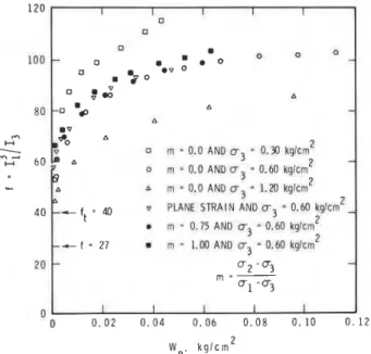
0.75 AND cr3 = 0.60 kglcrn2 - f = 2 7 m - l . 0 0 A N D ~ ~ = O . M k g l ~ m 2W p , k g l c m 2
FIG. 3. Variation of plastic work for dense Monterey No. 0 sand (after Lade and Duncan 1975).
plastic strain increment direction. Figure 2 illustrates the shape of the curves produced by the intersection of the plastic potential surfaces with the triaxial plane.
The work-hardening rule adopted for the model is an experi- mentally determined relation between the plastic work, W,, and stress level, f. Some of the test data used in the development of the hardening rule are shown in Fig. 3. These results indicate that the plastic work was very small for the range off starting with 27, at a hydrostatic state of stress up to a value called the threshold stress level,
f,.
In fitting curves to the experimental data, it was assumed that for values off between 27 andf,
no plastic strains occurred, and no plastic work was done. As shown in Fig. 4, the relation between Wp and (f -f,)
was approximated by a hyperbola for which equation [ S ] was pro- posed:The initial slope of a curve representing the Wp versus (f
-
f,)
relation is the reciprocal of the parameter a. The value of a increases with confining pressure, and this variation is ex- pressed asEVGIN AND EISENSTEIN 179 A S Y M P T O T E ---+
---
+---- 7 Y Y Y c T H R E S H D L D V A L U E 1=-
T O T A L P L A S T I C W O R KFIG. 4. Relation between plastic work and stress level.
where pa = atmospheric pressure and M and 1 = dimensionless numbers.
The parameter b in [5] is the reciprocal of the ultimate value of (f
-
f,),
which the hyperbola approaches asymptotically with increasing values of W,. This relation is given byAs the value of
Cf
- f,),,,, determined by a curve-fitting pro- cedure, was always larger than the value of (f - f,) at failure for finite values of W,, a new parameter called rf was introduced to relate the asymptotic value of (f - f,) to its value at failure, defined by[81 rf = (Kl - f,)
Cf-
f,>"ltIn the theory of plasticity the relation between plastic strain increments and the plastic potential function is expressed by
The determination of the proportionality constant
A
follows the development outlined by Hill (1950):in which the increment in plastic work for Lade's model is given by
- - - -
.- - -
a-d fThe plastic strain increments, expressed in suffix notation in
[ 9 ] , were also provided in matrix form:
[I21
Thus, the elastic and plastic parts of strain increments are fully described.
Previous applications of model
In order to verify the capabilities of the model a variety of tests with different stress paths were conducted and the comparative results were published by Lade and Duncan (1975,
1976). They concluded that the theory was reasonably accurate
for cohesionless soils for conditions of primary loading, unloading, and reloading. The theory was less satisfactory for proportional loading with increasing stresses, and for unload- inglreloading at constant confining pressure. As the strains observed in these cases were relatively small, the calculated strains were considered accurate enough for most purposes. The effectiveness of the theory in modelling stress-strain behaviour along several different stress paths was also confirmed by Medeiros (1979).
Ozawa (1974) was the first to develop a finite element program for Lade's model. It was used to analyse a hypo- thetical, passive earth pressure problem, which was also reported by Ozawa and Duncan ( 1 9 7 6 ~ ) . The results of this elastoplastic finite element analysis were compared with predic- tions using the hyperbolic model of Duncan and Chang (1970). Later, Ozawa and Duncan (19766) stated that the stress-strain relation derived in their earlier work and employed to analyse the earth pressure problem was in error. According to them, the errors were related to the plastic potential function and to calculations of the partial derivatives of the yield function. A new formulation of the constitutive matrix, containing all the required corrections, was published in detail by Duncan et al.
(1977).
Subsequently, Wong (1978) utilized Ozawa's program to incorporate the modifications proposed by Duncan et al. (1977) and analysed the behaviour of a model scale wall. Wong's calculations showed that the predictions were not even close to the actual measurements. Thus, these attempts to demonstrate the capabilities of Lade's work-hardening model did not at that time confirm its usefulness in solving engineering problems.
Previous modifications
Modifications and corrections for the model proposed by Ozawa and Duncan ( 1 9 7 6 ~ ) are as follows:
1. The plastic potential function was found to be mathemati- cally inconsistent with expressions for plastic strain increments and a new equation was proposed:
where a is a constant for a particular material and is defined as where A is the same as in [ 4 ] .
2. Owing to the error in the calculation of derivatives of plastic potential function with respect to shear stresses, the shear strain increments were in error by a factor of 2.0. On the right side of [12], therefore, the multiplier 2.0 of each term related to plastic shear strain increments had to be removed.
3. The parameter a , contained in [ 5 ] , varies with u3, accord- ing to [ 6 ] . This variation has to be taken into account in calculating df/d{u), which is used in finite element formulation to form the elastoplastic constitutive matrix.
With these corrections, the authors presented the elastoplastic constitutive relation in matrix notation suitable for use in a finite element analysis. Wong's (1978) predictions were based on this form of the model and utilized all the previous modifications.
CAN. GEOTECH. J . VOL. 22, 1985 I F I I 1 I I'
-
-
I-
1 0 3 III
STRESS PATH: 1 TO 2,/
Tea: REEVALUATED-
3
r e b : PREVIOUS MODIFICATIONS-
G1
STRESS PATH: 3 TO 4 G,: REEVALUATED AND-
,Zi
< I 1 PREVIOUS MODIFICATIONSSAME FOR BOTH METHODS
-
HYDROSTATIC A X l S I a ) I I 0 0.5 1.0 1 . 5 2 . 0-
I I I I I / I I-
DECREASING STRESSES AND INCREASING-
I-
1 /STRESS PATH FOR
1 CONVENTIONAL 1 T R l A X l A L TEST
-
-
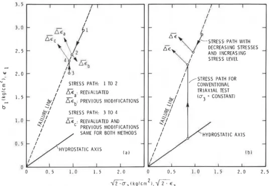
HYDROSTATIC A X l S - ( b l I 0 0 . 5 1.0 1 . 5 2 . 0 2 . 5 ~ ~ 3 1 k g l c m 2 1 . ~ c 3FIG. 5. Calculated and measured strain increments for two different stress paths (a) after Evgin and Eisenstein 1980, (b) after Lade and Duncan (1976).
Present work Using Fig. 4, the slope of the tangent to the W p versus (f -
f,)
New interpretation of work-hardening rule curve defines the relation between the increments off and W,. Lade's test results (Fig. 3) indicate that there is a unique According to the assumption made here, the point at which the relation between f and W , when u3 is constant. Figure 3 also tangent is taken pays little attention to the actual value of W,, shows data points for various m values while u3 is kept constant. but is specified by the known values off and u3. Depending on The variable m is defined as (a2 - u3)/(ul - us). These results the loading history of the soil, the accumulated value of W p may led Lade and Duncan (1975) to state that "the relationship vary for the same values off and u3. The increments of plastic between W , and f . .
.
depends on the confining pressure, u3, but work will, however, always be unique for a given state of stress it is essentially the same for all values of m." There are no test and stress increment. In mathematical form this statement is results with plastic work calculations to support the validity of equivalent to [ l 11, which is Lade's original equation for plastic [5] for stress paths with varying u3. This equation is, therefore, work increments. In other words, the amount of work- applicable strictly for stress changes for which u3 remains hardening in stress paths followed during conventional triaxialconstant. tests and in all the other possible stress paths is assumed to be the
The theory, first published by Lade and Duncan (1975), does same, provided that hardening is calculated at the same u3 not elaborate on this point, but simply treats the parameter a as a and f values. It may be concluded that the new interpretation of constant when [5] is used to derive an expression for the the work-hardening law makes full use of the experimental data increment of plastic work. As the stress states and the and of [5] without influencing adversely what has been increments of stresses were known, however, a was calculated formulated so far.
by Lade using u3 intermediate between its initial and final As an example of the differences between the predictions of values. Some of his predictions of laboratory tests were reported the present work and previous modifications, the behaviour of a in a subsequent publication (Lade and Duncan 1976). The soil in two stress paths was calculated; strain increments and the importance of the nongenerality of [5] for changing u3 values experimental results are compared in Fig. 5. When the stress has never been emphasized, however, nor has the basic path was similar to that of a conventional triaxial test, as assumption that allows its use in such problems been clearly
-
indicated by the line from point 3 to point 4, the strain increment stated. In publications by Ozawa and Duncan (1976a, b), [5] AE, was the same in both calculations. Experimental results remained a three-dimensional representation of the work- (Fig. 5b) were, in general, similar, but when the stress state hardening rule. Subsequently, as a deviation from Lade's followed the path from point 1 to point 2 the calculated values original work, Duncan et al. (1977) and Wong (1978) treated showed significant differences. While the - predictions of the the parameter a as a variable when a differentiation was needed present work indicate a strain increment, A€,, similar to thefor (51. measured value, the calculated strain increment (using the
The consequences of assuming that [5] is unique for general previous modifications), Acb, was in the wrong direction. three-dimensional problems have been illustrated by Evgin and
Eisenstein (1980). In fact, for soils there is no unique relation Wong's experimental investigations
between f and W,, except for the conventional triaxial stress Experimental work carried out by Wong (1978) forms the path. In order to use [5] in the analysis of a general three- basis of comparison for the present finite element analysis. For dimensional problem, where u3 generally changes during this reason the relevant part of Wong's work will be presented. loading, an assumption has to be made to establish a criterion In a series of passive pressure tests a segmented wall was about how the yield surface will expand as the plastic work is instrumented and rotated about its toe into a bed of sand, as
EVGIN AND EISENSTEIN
J J
A N G L E OF W A L L Y Y
R O T A T I O N
FIG. 6. Instrumented wall for passive pressure tests (after Wong 1978).
aoa
2 4 6
ANGLE OF WALL ROTATION, degree
I I r N O R M A L S T R E S S
-
I I I1
-
I IFIG. 7. Experimental results for dense sand. Variations of average normal and shear stresses and passive earth pressure coefficient with angle of wall rotation (after Wong 1978).
were taken on the panels at various stages of rotation. The outcrops of the slip planes on the surface were mapped at the end of each experiment. Tests were conducted using dense ( D , =
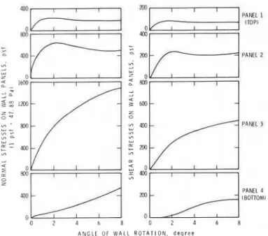
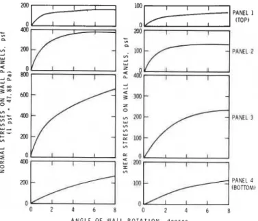
90%) and medium dense ( D , = 65%) Monterey No. 0 sand. Figures 7 and 8 show average normal and shear stresses on the wall as well as the coefficient of passive earth pressure, K,, for two relative densities of sand. The distribution of these stresses along the wall is given in Figs. 9 and 10. The mobilization of stresses follows a pattern that can be summarized as follows. As the wall is rotated, normal and shear stresses acting on the top panel reach their peak before those acting on the lower panels. With increasing rotation, failure spreads downwards along the wall, and larger portions of the soil mass located away from the wall fail. The stress level of the soil immediately in front of the lower portions of the wall does not become sufficiently high to induce failure. As shown in Figs. 9 and 10, normal stresses on the third and fourth panels do not show any sign of reaching a peak even at 8" of wall rotation.
Finite element analysis
For the present application a special-purpose finite element
I I I
-
-
N O R M A L S T R E S S \-
0 0 2 4 6 8ANGLE OF WALL ROTATION, degree
FIG. 8. Experimental results for medium dense sand. Variations of average normal and shear stresses and passive earth pressure coefficient with angle of wall rotation (after Wong 1978).
PANEL 3
PANEL 4 (BOTTOM1
ANGLE OF WALL ROTATION, d e g r e e
FIG. 9. Experimental results for dense sand. Distribution of normal and shear stresses on four panels of wall (after Wong 1978). program was developed to predict the behaviour of Wong's instrumented wall. The new interpretation of the work-harden- ing rule was used when the model was implemented in the finite element program (Evgin 1981). Two analyses were performed to predict the experimental results of passive earth pressure tests for dense and medium dense sands.
Soil parameters
Representative soil parameters for analysis of wall behaviour were obtained from the triaxial test data provided by Lade (1972). The procedures followed in calculating the soil para- meters were the same as those described by Lade and Duncan (1975). Their values are listed in Table 1 .
Boundary conditions
The finite element mesh and the boundary conditions for analysis of the rigid wall are shown in Fig. 11. The horizontal displacements of the nodes along the rotating wall and soil interface were specified for each load increment. Measurements of shear stresses (Figs. 9 and 10) were used in calculating the
182 CAN. GEOTECH. J. VOL. 22, 1985 PANEL 4 (BOTTOM) 0 0 2 4 6 8 0 2 4 6 8 ANGLE OF W A L L R O T A T I O N , d e g r e e 1 I I
P
- 0-0 P R E S E N T S T U D Y E X P E R I M E N T A L I I I-
IANGLE OF WALL ROTATION, degree
FIG. 10. Experimental results for medium dense sand, &tribution FIG. 12. Variation of average normal Stress with wall rotation for of normal and shear stresses on four panels of wall (after Wong 1978). dense
monte re^
No. 0 sand. Predictions of Present study and experi-mental results of Wong (1978).
TABLE 1. Stress-strain parameters used in present study for Monterey No. 0 sand
Parameter Dense sand Medium dense sand 1693.0 0.85 0.0 64.0 33.9 0.397 16.28 1.19 0.00062 0.968 B O U N D A R Y C O N D I T I O N S A L O N G A A N D C : O N L Y V E R T I C A L D I S P L A C E M E N T S A L L O W E D A L O N G B : D I S P L A C E M E N T S N O T P E R M I T T E D A L O N G 0: H O R I Z O N T A L D I S P L A C E M E N T S A N D S H E A R F O R C E S S P E C I F I E D A L O N G E: F R E E T O M O V E
FIG. 11. Finite element mesh and boundary conditions for analysis of rigid wall.
z Z
2
2 l z o n ] -lD 4 -0 P R E S E N T S T U D Y-
E X P E R I M E N T A L PANEL 1 (TOP1 PANEL 2 I 2 3 4 A N G L E OF W A L L R O T A T I O N , d e g r e eFIG. 13. Distribution of normal stresses along the wall for dense Monterey No. 0 sand. Predictions of present study and experimental results of Wong (1978).
equivalent shear forces to be applied to the nodes, so that the wall was no longer needed in the analysis.
Analysis of wall behaviour for dense sand
Results of the analysis involving dense sand are shown in Figs. 12 and 13. The calculated average normal stress and its distribution along the wall are plotted against the angle of wall rotation. In addition, average values of the coefficient of passive earth pressure may be seen in Fig. 12. Variation of K , for each panel is calculated separately (Table 2).
Analysis of wall behaviour for medium dense sand
EVGIN AND EISENSTEIN 183
TABLE 2. Measured versus calculated passive earth pressure coefficient K p for each wall panel (dense sand)
Wall rotation = 0.5" Wall rotation = 1 .OO
Wall Measured Calculated Measured Calculated
panel KP KP KP KP
TABLE 3. Measured versus calculated passive earth pressure coefficient K p for each wall panel (medium dense sand)
Wall rotation = 0.5" Wall rotation = 1 .OO
Wall Measured Calculated Measured Calculated
panel K P KP KP KP
ANGLE OF WALL ROTATION, degree
FIG. 14. Variation of average normal stress with wall rotation for medium dense Monterey No. 0 sand. Predictions of present study and experimental results of Wong (1978).
? O 0 L - -
0:::r
0 2 0 0 0-n P R E S E N T S T U D Y PANEL 1 (TOP) PANEL 2 PANEL 3 J 8 E X P E R I M E N T A LI
I I ! I z PANEL 4 (BOTTOM) 0 1 2 3 4 5 A N G L E O F W A L L R O T A T I O N , d e g r e eFIG. 15. Distribution of normal stresses along the wall for medium dense Monterey No. 0 sand. Predictions of present study and experi- mental results of Wong (1978).
ANGLE OF WALL ROTATION, degree
0 . 5
FIG. 16. Predicted zones of high stress level as a function of wall rotation for medium dense Monterey No. 0 sand.
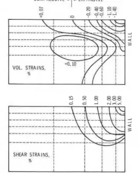
distribution along the wall. The average coefficient of passive earth pressure is illustrated in Fig. 14, and the breakdown of K, into each panel is given in Table 3. Growth of highly stressed zones for medium dense sand is shown in Fig. 16, and contours of cumulative shear strain and volumetric strain are given in Fig.
17.
Interpretation of$nite element results
The main objective has been to determine the agreement between predictions made using Lade's model and experimental results for a complex boundary value problem. The behaviour of the soil-wall interface was not modelled, but available informa- tion about the shear stresses acting on the wall was used as input on this boundary. In this way the unresolved issue of modelling interface behaviour was avoided. It is assumed that for given horizontal displacements the normal stresses acting on the wall can only be calculated successfully if the behaviour of soil mass is modelled properly.
Generally, comparisons indicate good agreement between the observed normal stress distribution on the wall and
184 CAN. GEOTECH. J. VOL. 22, 1985
COMPRESSTVE
-t-
EXPANSIVEFIG. 17. Predictions for contours of cumulative shear strains and volumetric strains at 2' of wall rotation for medium dense Monterey No. 0 sand.
8 . A N G L E O F W A L L R O T A T I O N A B O U T T H E T O E
FIG. 18. Rupture planes observed on radiographs exposed at three stages of wall rotation (after James and Bransby 1970).
measured values up to a rotation angle of 2" for dense sand and
3.6" for medium dense sand. At this stage the analyses were
terminated. Predictions of zones of high stress level and their growth as a function of wall rotation agree well with the measured values. Predictions at working load range as well as at high stress levels were generally good.
In relation to the passive earth pressure problem, deformation patterns and failure surfaces developed in experiments were observed earlier by James and Bransby (1970). In their experiments, rupture surfaces (Fig. 18) did not start from the toe of the wall, rotating about its base. Even at large deformations, the failed zone extended only from the surface to somewhere near the middle of the wall. Present calculations using Lade's constitutive equations predicted this type of behaviour (Fig.
16). This is a good example of a case in which part of the soil
mass is in a state of failure even at the early stages of testing, while the remainder is still loading. It appears that realistic analysis of the passive earth pressure problem requires that both deformation properties and failure conditions of soils must be represented reasonably well.
Conclusions
A new interpretation of Lade's work-hardening rule for
cohesionless soils has been applied in analysing a complex boundary value problem. Comparison of experimental results of passive earth pressure tests with analytical results indicates that the model works reasonably well for a wide range of loading. Although, the limited results obtained in the present study do not warrant general conclusions, the model has the potential to provide reliable predictions for deformations in soil structures.
Acknowledgement
The authors gratefully acknowledge the assistance provided by the Division of Building Research, National Research Council of Canada.
CHRISTIAN, J. T. 1980. State-of-the-art report. The application of generalized stress-strain relations. Application of plasticity and generalized stress-strain in geotechnical engineering. Proceedings, Symposium on Limit Equilibrium, Plasticity and Generalized Stress-Strain Applications in Geotechnical Engineering, ASCE. Edited by R. N. Yong and E. T. Selig., pp. 182-204.
DUNCAN, J. M., and CHANG, C.-Y. 1970. Nonlinear analysis of stress and strain in soils. ASCE Journal of the Soil Mechanics and Foundations Division, 96(SM5), pp. 1629-1653.
DUNCAN, J. M., OZAWA, Y., LADE, P. V., and BOOKER, J. R. 1977. An elasto-plastic stress-strain relationship for cohesionless soil. Ninth International Conference on Soil Mechanics and Foundation Engineering, Specialty Session No. 9, Tokyo, Japan, pp. 45-50. EVGIN, E. 1981. Evaluation of an elasto-plastic model. Ph.D. thesis,
University of Alberta, Edmonton, Alta., Canada.
EVGIN, E., and EISENSTEIN, Z. 1980. Re-evaluation of work hardening model. Application of plasticity and generalized stress-strain in geotechnical engineering. Proceedings, Symposium on Limit Equil- ibrium, Plasticity and Generalized Stress-Strain Applications in Geotechnical Engineering, ASCE. Edited by R. N. Yong and E. T. Selig., pp. 226-239.
HILL, R. 1950. The mathematical theory of plasticity. Oxford University Press, London, England.
JAMES, R. G., and BRANSBY, P. L. 1970. Experimental and theoretical investigations of a passive earth pressure problem. Geotechnique, 20, pp. 17-37.
KONDNER, R. L. 1963. Hyperbolic stress-strain response. ASCE Journal of the Soil Mechanics and Foundations Division, 89(SM1), pp. 115-143.
LADE, P. V. 1972. The stress-strain and strength characteristics of cohesionless soils. Ph.D. thesis, University of California, Berkeley, CA, U. S. A.
1977. Elasto-plastic stress-strain theory for cohesionless soil with curved yield surfaces. International Journal of Solids and Structures, 13, pp. 1019-1035.
LADE, P. V., and DUNCAN, J. M. 1975. Elastoplastic stress-strain theory for cohesionless soil. ASCE Journal of the Geotechnical Engineering Division, 101(GT10), pp. 1037- 1053.
1976. Stress-path dependent behavior of cohesionless soil. ASCE Journal of the Geotechnical Engineering Division, 102(GT1), pp. 51-68.
MEDEIROS, L. 1979. Deep excavations in stiff soils. Ph.D. thesis, University of Alberta, Edmonton, Alta., Canada.
OZAWA, Y. 1974. Elasto-plastic finite element analysis of soil deformation. Ph.D. thesis, University of California, Berkeley, CA, U. S. A.
OZAWA, Y., and DUNCAN, J . M. 1976a. Elasto-plastic finite element analyses of sand deformation. Proceedings, 2nd International Conference on Numerical Methods in Geomechanics, Blacksburg, VA, U.S. A , , pp. 243-263.
1976b. Correction to elasto-plastic finite element analyses of sand deformation. Proceedings, 2nd International Conference on Numerical Methods in Geomechanics, Blacksburg, VA, U. S. A,, pp. 1477-1479.
WONG, K. S. 1978. Elasto-plastic finite element analyses of passive earth pressure tests. Ph.D, thesis, University of California, Berkeley, CA, U. S. A.
EVGlN AND ElSENSTElN
List of symbols
parameter for work-hardening rule material constant
parameter for work-hardening rule stress level
threshold stress level plastic potential first stress invariant third stress invariant stress level at failure
parameter for plastic potential dimensionless number ( a 2
-
u ~ ) / ( u I-
~ 3 ) dimensionless number atmospheric pressure relatesCf
-
ft)
to (K1 - f,) plastic work coordinate axesconstant for plastic potential function total strain elastic strain plastic strain proportionality constant normal stress principal stresses shear stress