HAL Id: hal-02014572
https://hal.univ-lorraine.fr/hal-02014572
Submitted on 18 Dec 2020HAL is a multi-disciplinary open access archive for the deposit and dissemination of sci-entific research documents, whether they are pub-lished or not. The documents may come from teaching and research institutions in France or abroad, or from public or private research centers.
L’archive ouverte pluridisciplinaire HAL, est destinée au dépôt et à la diffusion de documents scientifiques de niveau recherche, publiés ou non, émanant des établissements d’enseignement et de recherche français ou étrangers, des laboratoires publics ou privés.
Review of the current technologies and performances of
hydrogen compression for stationary and automotive
applications
Giuseppe Sdanghi, Gaël Maranzana, Alain Celzard, Vanessa Fierro
To cite this version:
Giuseppe Sdanghi, Gaël Maranzana, Alain Celzard, Vanessa Fierro. Review of the current technologies and performances of hydrogen compression for stationary and automotive applications. Renewable and Sustainable Energy Reviews, Elsevier, 2019, 102, pp.150-170. �10.1016/j.rser.2018.11.028�. �hal-02014572�
1
Review of the current technologies and
performances of hydrogen compression for
stationary and automotive applications
G. Sdanghi
1,2, G. Maranzana
2, A. Celzard
1, V. Fierro
1*1
Institut Jean Lamour, UMR CNRS-Université de Lorraine n°7198, ENSTIB, 27 rue Philippe Seguin, BP 21042 - 88051 EPINAL Cedex 9, France
2
Laboratoire d'Energétique et de Mécanique Théorique et Appliquée, UMR CNRS- Université de Lorraine n° 7563, 2 avenue de la Forêt de Haye, BP 160, F-54504 Vandœuvre-lès-Nancy, France
*
Corresponding author. Tel: + 33 329 29 61 77. Fax: + 33 329 29 61 38. E-mail address :
2 Abstract
Hydrogen could play an important role as energy vector in the next decades in the frame of the Sustainable Development. It is the most abundant element of the universe, and virtually available everywhere, thus being a never-ending source of energy. Hydrogen can be directly converted into electric energy by using fuel cells, without producing toxic gases. Moreover, it can be produced by renewable sources such as biomass, solar and wind energies, thus having no impact on the environment. However, even if hydrogen offers a promising eco-friendly solution for the energy transition, in order to foreseen its wide use in both stationary and automotive applications, several issues related to its storage and delivery have to be solved. Indeed, hydrogen has lowest volumetric energy density among the commonly used fuels, i.e., 0.01079 MJ/L at atmospheric pressure. Compression is the direct solution to overcome this barrier. High pressures can indeed give satisfying energy densities. The present review summarises the state of the art of the most classical hydrogen compression technologies. The technical and design features of mechanical compressors, i.e., reciprocating, diaphragm, linear and ionic liquid compressors, as well as of innovative non-mechanical technologies specifically conceived for hydrogen applications, such as cryogenic, metal hydride, electrochemical and adsorption compressors, are presented. The basic operating principles and the performances potentially achievable for each compression technology are analysed. Specifically, their current uses in hydrogen applications, as well as their technological limits, are described outlining the possible actions to be taken for improving their performances.
Keywords: Hydrogen compression; Mechanical compressors; Cryogenic compressors; Metal hydride compressors; Electrochemical compressors; Adsorption compressors.
3 1. Introduction
The growing global energy demand, as well as the increasing concerns about environmental pollution, has made hydrogen a realistic alternative to the traditional fossil fuels. The world energy consumption is indeed expected to double over the next half century, so significant changes in producing, distributing, storing and using energy are necessary (1). Hydrogen can be the ideal solution to all these issues. Hydrogen is the most abundant element in the universe, thus being a never-ending and renewable source of energy. Furthermore, hydrogen can be produced from renewable and sustainable resources, thus offering a promising eco-friendly solution for the energy transition expected in the next decades. Hydrogen production from water by electrolysis is nowadays considered the main sustainable alternative to hydrogen synthesis from fossil fuels (2). Hydrogen production from biomass has shown to be a cost effective solution as well, both by using supercritical water gasification (3) and fermentative processes (4). Solar energy is also another sustainable and environmentally friendly way to produce hydrogen (5,6). Hydrogen exhibits the largest gravimetric energy density among non-nuclear fuels, and can be easily converted into thermal, mechanical and electrical energy (7). Its use in both stationary and automotive applications, such as fuel cells, offers a promising way to use electrical and thermal energies without impact on the environment, opening a new scenario in the use of sustainable energy all over the world (7– 10).
Despite such advantages, two main issues prevent the generalised use of hydrogen as an efficient fuel, and with this, the energy transition towards a compelling fossil-free solution. Firstly, hydrogen is an energy vector, and this means that it is necessary to produce it before use, so energy is needed to synthesise hydrogen (11). Secondly, hydrogen exhibits the lowest volumetric energy density among the commonly used fuels, 0.01079 MJ/L at standard temperature and pressure (12), much lower than that of gasoline, 34 MJ/L (13). In order to
4 increase this value, several methods have been developed: (i) compression in gas cylinders; (ii) liquefaction in cryogenic tanks; (iii) storage in metal hydride alloys; (iv) adsorption onto large specific surface area-materials and (v) chemical storage in covalent and ionic compounds (formic acid, borohydrure, ammonia..) (14). Among them, compression of hydrogen is the most widespread method to store hydrogen, even if it is not the cheapest one (15). Gaseous hydrogen at high pressures is particularly used in the frame of the Haber process for ammonia production, as well as to carry out hydro-cracking of heavy petroleum fractions in order to produce lighter hydrocarbons (16).
During the last years, a significant attention has been paid to the efficient use of hydrogen in automotive applications (17,18). Moreover, a “Hydrogen Economy” is often advocated as a potential way to deliver sustainable energy through the use of hydrogen (19). In this context, after being produced and before using it, hydrogen is packaged, distributed, stored and delivered, the most complex issues to solve related especially to the latter two steps (20). It has been shown that the cheapest hydrogen storage-delivery mode is obtained by compression and delivery with a truck, especially for small stations and low demands (21). For this reason, efforts have been carried out in order to improve compression solutions for hydrogen storage. It has been also shown that the introduction of new and sophisticated materials, like carbon fibre- and glass fibre-reinforced tanks, allowed a significant reduction of the storing system weight, increasing in turn the hydrogen volumetric energy density (22). Commercial vessels available nowadays achieve an average hydrogen content of 1-2 wt.% at pressures of about 20-25 MPa (23), but composite pressure tanks up to 70 MPa have also been successfully developed, reaching a gravimetric storage density of 6 wt. % and a volumetric storage density of 30 g/L (24). These values still don’t meet the two U.S. Department of Energy targets, which set the ideal gravimetric and volumetric capacity for hydrogen automotive systems to 40 g/L v/v and 5.5 wt.% for 2017 (25,26), respectively, to be achieved in the temperature
5 range 233-358 K (27). Moreover, not only the weight of the storage material but also that of the entire system should be taken into account. At present, current compression methods are unlikely to satisfy these targets (28), but at the same time they are mature enough to ensure the 70 MPa required by the on-board hydrogen storage systems used in the Fuel Cells Vehicles as well as by the hydrogen refuelling stations (29).
The present review summarises the state of the art of the hydrogen compression technologies used for both stationary and automotive applications involving hydrogen as renewable fuel. The technical and design features, the basic operating principles and the level of performances potentially achievable for each single compressor technology are analysed, emphasising their advantages as well as their drawbacks. Specifically, their current use in hydrogen applications is described, focusing also on the technological limits and outlining the possible actions to be taken for improving their performances.
Fig. 1 – Summary of the hydrogen compression technologies currently used for stationary and automotive applications
6 2. Mechanical Compressors
Mechanical compressors are the most widespread type of compressors used nowadays, based on the direct conversion of mechanical energy into gas energy. Among the several typologies, the “positive displacement” devices are particularly used for hydrogen compression, consisting in the reduction of the confined volume in which hydrogen is contained by the use of a piston: gaseous hydrogen is squeezed into a smaller space, so that the number of collisions among particles and with the walls increases (30), resulting in a higher gas pressure.
2.1 Reciprocating piston compressors
Reciprocating compressors, especially the oil-free ones, are commonly used for hydrogen applications when the desired level of pressure is higher than 3 MPa (31). They are ideal for moderate flow and high-pressure applications: the required power consumption can be as large as 11.2 MW, with a resultant hydrogen flow as high as 890 kg/h and a discharge pressure of 25 MPa (15). Higher discharge pressures up to 85 MPa are achieved by HydroPac, Inc. reciprocating hydrogen compressors, with an inlet pressure of 35 MPa and a capacity of around 430 kg/h (32).
Basically, a single-stage reciprocating compressor consists in a piston-cylinder system (Fig. 2), equipped with two automatic valves, one for intake and one for delivery. The piston is linked to a crankshaft through a connecting rod, converting the rotary motion of the moving units into the almost linear motion of the piston. This movement is known as reciprocating motion (33). The energy necessary for the compression is given by either an electrical or a thermal machine. The piston movement towards the upper side of the cylinder, i.e., the Top Dead Centre (TDC), creates a partial vacuum in the lower part of the cylinder itself, opening
7 the intake valve and allowing the gas to enter it. The consequent suction phase lasts until the piston reaches the Bottom Dead Centre (BDC), then the intake valve is closed. Moving again towards the TDC, the gas is compressed until the pressure reaches the desired level, then the delivery valve is opened, discharging the gas.
Fig. 2 – Scheme of a reciprocating piston compressor
Reciprocating compressors produce high-pressure hydrogen especially when a multistage configuration is adopted (34): a first stage of compression increases the hydrogen pressure up to a couple of atmospheres, before reaching the target value through the next stages. Actually, this configuration is particularly preferred in on-site hydrogen refuelling stations, where hydrogen is generated at a pressure around 0.6 MPa, making necessary in turn the use of an efficient compressor system in order to supply hydrogen to a fuel cell vehicle (35). On the other hand, reciprocating compressors are not efficient for high flow rates (36,37). In fact, the flow rate depends on the dimension of the cylinder, as well as on the number of cycles per unit time, called speed of compression. An increase of the cylinder dimension results in bigger and heavier components, increasing in turn the inertia forces. In order to limit the resulting mechanical stresses, a decrease of speed is thus recommended. Hence, high
8 compression speeds are achievable only in small cylinders, then causing a reduction of the allowable flow rates.
The embrittlement phenomena are the main drawback to overcome in hydrogen reciprocating compressors (38), making necessary a careful selection of the material used, as well as a sophisticated design. Several guidelines have to be followed, according to the API
Standards 618, in which all the minimum requirements for reciprocating compressors are
included (39). The cylinders, commonly made of cast iron, nodular cast iron, cast steel and forged steel (40) are covered by a liner coat, ensuring the walls protection. Being easily removable, the liner reduces repair costs in case of accident, and facilitates the adjustment of the cylinder diameter, depending on the operational requirements, thus providing an advantageous versatility to the system (41).
Since the use of lube oils can affect the durability of the compressor components, oil-free compressors are preferred, offering high performances operation and high-purity compressed gas (42). Hence, in order to prevent the contact between the piston and the cylinder (43), pistons are equipped with wear bands, usually known as rider bands, made of thermoplastic materials (44). In order to reduce as much as possible hydrogen leakages, piston rings are also used (45). Nevertheless, it has been proved that high-pressure oil-free hydrogen reciprocating compressors are particularly affected by the early failure of the sealing rings, because of a large non-uniformity of the pressure distribution inside the compression chamber (46). For this reason, a two-compartment distance piece has to be included in the design of the compressor to facilitate gas venting (39), avoiding in this way the embrittlement of the steel due to hydrogen escaped from the compression chamber.
Nowadays, the 94/9/EC European Directive concerning equipment used in potentially explosive atmospheres is also complied by the Member States of the European Union for manufacturing reciprocating compressors (47). By choosing carefully the wear materials, by
9 adopting a conservative design as well as by reducing the piston speed, good performances can be reached. During the last years, better reciprocating compressors have been developed for hydrogen applications, improving significantly the operating parameters: discharge pressures of 100 MPa and flow capacities of 300 Nm3/h have indeed been reached (48).
Although reciprocating compressors are widely used for applications involving hydrogen, several limitations make them not perfectly appropriate for such purpose. Firstly, the presence of several moving parts increases the cost, because of the manufacture complexity as well as the difficulty to provide a good maintenance (49). Moreover, such typology prevents the efficient cooling of hydrogen during the compression because of the presence of moving parts, like the piston, resulting in an increase of the heat produced and in a more difficult management of thermal transfers (50). In addition, the back and forth movement of the piston causes pressure fluctuations inside the compression chamber, which can be detrimental since they may cause vibrations, noises, even explosions, and hence lead to a decrease of the system life of the overall hydrogen plant (51). Anyway, it is noteworthy that the reciprocating compressors exhibit very good performances especially when the multi-stage configuration is used, because of the high value of the discharge pressure reached and because of their flexibility in size and capacity. Several improvements have been achieved in their design, like the upgrading to non-metallic ring and valves materials, the use of a tungsten carbide piston rod coating, and the implementation of continuous monitoring systems to predict possible failures (52). However, the aforementioned drawbacks attract interest for other devices aimed at compressing hydrogen more efficiently. Table 1 gathers the main characteristics of a few representative examples of reciprocating compressors.
10 Table 1 – Hydrogen reciprocating compressors
RECIPROCATING COMPRESSORS Pin [MPa] Pout [MPa] Flow [Nm3/h] Applications Efficiency [%] Leonard S. M. (52) 0.4 25.5 no data - Catalytic reformers
- Hydrogen plants no data
Amos W. A. (15) no data 25 ~ 10000 - Compressed gas storage no data
Kurita et al. (35) 0.6 70 (5 stages) no data - Hydrogen refuelling
stations no data
Hydropac (32) 35 85.9 4820
- Filling vehicle tanks - Moving gas between storage vessels
no data
Hitachi Infrastructure System (48)
0.6 100 300 - Hydrogen stations no data
Advantages
- Mature technology
- Adaptability to a large range of flow rates - High discharge pressures
Disadvantages
- Contamination by lube oils (if used) - Embrittlement phenomena
- Several moving parts - Manufacturing complexity
- Difficulty to provide good maintenance - Difficulty in managing the thermal transfer - Presence of vibrations and noise
No data means that the information was not provided in the corresponding references.
2.2 Diaphragm compressors
Thanks to their high throughput, lower power consumption and low cooling requirements, diaphragm compressors have been proved to be very effective for hydrogen applications (53). Generally, they fit well when highly chemically pure gases have to be handled, since the direct contact between the gas and the piston is prevented (54)(55). In fact, the gas is completely isolated from the piston, since its movement is transmitted to a hydraulic fluid, which in turn transmits the motion to a thin metal membrane called “diaphragm”, isolating hydrogen from the hydraulic part. The forth movement of the diaphragm into the cavity space, in which the gas is confined, reduce the available volume, thereby allowing an increase of the gas pressure (Fig. 3).
11 Fig. 3 – Scheme of a metal diaphragm compressor
Actually, the diaphragm is composed of three different plates (56): (i) the process plate, on the hydrogen side, coming in contact exclusively with it; (ii) the hydraulic plate, on the hydraulic fluid side and (iii) the middle plate, set between the former two units, with the purpose of detecting eventual leaks and avoiding the diaphragm failure.
The hydraulic fluid in a diaphragm compressor is essentially oil. Whereas in reciprocating compressors oil could be used exclusively for lubricating purposes, in the diaphragm typology it directly controls the diaphragm movement (57). A specific hydraulic circuit provides oil to the hydraulic space (57), and is equipped with a hydraulic pressure limiter monitoring the pressure level beneath the diaphragm. A perforated plate acts as oil distributor, in order to achieve a uniform pressure load on the diaphragm plates. The oil pressure control is crucial in order to obtain good efficiencies, since once the gas is discharged and the diaphragm group is completely deflected in the discharge position, the piston still has to reach its TDC position. As a consequence, the pressure inside the oil space increases, becoming higher than the gas discharge pressure. Hence, the hydraulic pressure limiter is opened at a value slightly higher
12 than the one set for the gas discharge, reducing the eventual liquid-gas pressure differential across the diaphragm and thus increasing the service lifetime of the whole system (58). The presence of a separate circuit for the compressing oil makes also possible the integration of a cooling system, so that the heat produced during the compression step can be effectively withdrawn (59).
Since the diaphragm is in contact at the same time with hydrogen on one side and with oil on the other side, a careful selection of the building materials is of key importance (60), with respect to the basic requirements of high corrosion resistance and high durability. Stainless steel, stainless chrome nickel steel, alloys from copper-beryllium and duplex steel are the materials commonly used for the diaphragm plates (61). Diaphragm compressors acts properly to minimise the hydrogen leakages, since the hydrogen circuit is a closed loop well separated from the oil one, with the result that the purity of the gas is kept always very high (62). This feature seems to be crucial considering that hydrogen leakages affecting the mechanical compressors are the primary risk factor in hydrogen refuelling stations (63).
Diaphragm compressors are able to reach very high volumetric efficiencies, which are beneficial for energy saving (64). However, one of the most important drawbacks of this kind of compressors is related to their durability, as they are weakened by the mechanical stresses during operation. Since too high flow rates can cause the early failure of the diaphragm, a good design includes concavities and grooves ensuring proper flow distributions (65). Diaphragm compressors are appropriate especially for applications requiring low flow rates (66), due also to the limited volume of the compression chambers commonly employed (67). Diaphragm failure can be also caused by the radial stresses related to the diaphragm deflection (68), and strictly correlated to the geometry of the cavity space in which it moves. Further stresses can arise from the contact between the diaphragm and the perforated plate (63), causing fractures on the edge of the diaphragm and hence compromising the overall
13 compressor operation. Hence, new designs of the diaphragm plates have been proposed by numerical simulation models (69–71).
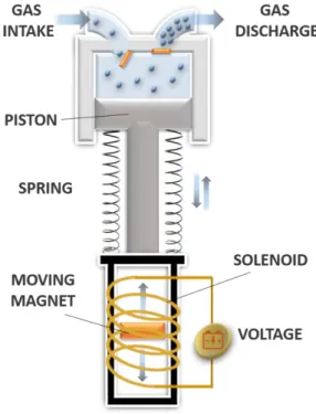
The high efficiency, compactness, good scalability and absence of complex sliding mechanisms make the diaphragm compressors well-suited even for microscale applications (72). With the recent development of the microelectromechanical systems (MEMS), the demand for micro-compressors considerably increased, and efforts are being focused on their development (73). For instance, a MEMS based on an innovative electrostatic diaphragm compressor has been developed (74). Instead of using the motion of a piston, the compression is produced by a dc voltage applied between the edges of the compression chamber and the diaphragm by means of metal electrodes (Fig. 4). The electric field generated in the chamber forces the diaphragm to move towards the surface on which the voltage is applied, and the resultant volume reduction increases the gas pressure. The polarity of the applied voltage is varied cyclically, allowing the gas compression in both halves of the cavity space. In order to avoid electric shorting when the diaphragm comes in contact with the surfaces of the chamber, dielectric coating layers are deposited on the top of the metallic electrodes (75).
14 Electrostatic diaphragm compressors might offer a good solution for hydrogen compression in small size facilities, even though today traditional compressors remain the most used. The German company Hofer Hochdrucktechnik (61), well-known worldwide for their hydrogen diaphragm compressors, has equipped several hydrogen refuelling stations compressing the gas at around 390-581 Nm3/h with a discharge pressure up to 28.1 MPa (61).
On the other hand, the American company PDC machines (76) is leader in manufacturing diaphragm hydrogen compressors for fuel cells vehicles; these compressors operate at a discharge pressure of 51.7 MPa and flow rates from 50 to 280 Nm3/h.
Even though diaphragm compressors exhibit several advantages, on average, one of the most compelling goals is currently the optimisation of the diaphragm design in order to reduce its risk of failure. Achieving this goal could mean the realization of efficient hydrogen vending stations, reaching the DOE’s target of implementing a strong hydrogen distribution network (77). Table 2 gathers the main characteristics of a few representative examples of hydrogen diaphragm compressors.
Table 2 – Hydrogen diaphragm compressors
DIAPHRAGM COMPRESSORS Pin [MPa] Pout [MPa] Flow [Nm3/h] Application Efficiency [%] Hofer (61) 0.5 15.1 5.5 no data no data 0.9 9.7 390 no data no data 1.1 25.1 112 no data no data 1.8 28.1 581 no data no data 2.6 18 450 no data no data
2.8 9.7 no data no data no data 3 - 3.5 4.77 - 4.84 556 no data no data
PDC Machines (76) no data 51.7 50 - 280 - Hydrogen fuel
cells vehicles no data
Weinert et al. (78) 1.3 43 no data - Hydrogen
refuelling stations 65
Tzimas et al. (66) no data 100 200 - 700 no data 80 - 85
Advantages
- High throughput
- Low power consumption - Low cooling requirement
- Ideal for handling pure gases or explosives
Disadvantages - Diaphragm failure
15 2.3 Linear compressors
Linear compressors are particularly used in cryogenic applications driven by Stirling cycle coolers and involving hydrogen and helium gas (79,80), as well as for domestic refrigeration (81). Compared to the former mechanical compressors, the piston is directly connected to a linear motor coupled with a resonating spring system (Fig. 5), reducing the number of moving units because of the absence of rod-crank assembly.
Fig. 5 – Scheme of a linear compressor
The low number of rotating components makes the arrangement of the whole system simpler with regards to the aforementioned compressors, leading at the same time to significant cost savings (82). Nevertheless, for stationary, industrial and automotive applications, there are no references about the use of linear compressors for hydrogen applications, being considered as an innovative way to compress hydrogen since a few years only (62).
16 The targets set by the US Department of Energy (DOE), focused on the increase of the compression efficiency as well as on the cost reduction of hydrogen compressors, have made linear compressors very attractive. The design of linear compressors is consolidated nowadays, and several thermodynamic studies have deepened the overall knowledge of this technology during the last years (83). The linear motors commonly used for driving the piston are magnetic-type, and more specifically moving-coil (84–86) and moving-magnet types (85). The Oxford moving-coil linear motor has been used for a long time, especially in aerospace applications, because of its high efficiency, low vibration, low noise emissions and long operation life (87). Basically, this motor consists of a series of hollow coils moving only in the axial direction and immersed in a radial strong magnetic field. Despite their structural simplicity, moving-coil motors require large amounts of permanent magnets to achieve high efficiencies. The moving-magnet motor therefore seems to be the best alternative, exhibiting high reliability, low material outgassing rate and a good thermal dissipation (88). This motor is composed of a permanent magnet divided in two separate parts, in the middle of which a moving magnet directly controls the axial movement of the piston (89), providing high magnetic fluxes with only a small amount of magnets (90). By inverting the polarity of the voltage applied to the magnet through the use of electronic circuits or inverters, the direction of the piston stroke is thus inverted, allowing both expansion and compression steps.
Magnetic motors for linear compressors are designed to work at the mechanical resonance frequency, so that the required energy for the piston displacement is transferred without large driving forces (91), thereby minimising the driving electric current as well as the Joule losses in the coil. Linear compressors work at the mechanical resonance when their operating frequency is set to the natural frequency value (92), and by doing such frequency adjustment, very high efficiency levels can been achieved (93). If the working frequency deviates from the resonance value, the system is no longer able to work in the optimum conditions: for this
17 reason, an additional control system for the frequency is required. The resonance frequency of the compressor can be obtained from the following equation (94):
(1)
where kgas is the stiffness of the gas spring, kmechanic is the axial stiffness of the mechanical
springs and m is the moving mass. The stiffness of the gas spring can be obtained from the Hooke’s law by considering the gas like a spring pulling and pushing the piston (87), whereas the stiffness of the mechanical springs is a function of their length, width and thickness. Actually, the evaluation of the resonant frequency is not easy, because of the nonlinearity affecting the gas spring, varying continuously throughout the operation (95).
A clear advantage in using linear compressors is that the piston and the cylinder are separated by a gas bearing system (86), consisting in driving back into the compression chamber an established amount of high-pressure gas, which acts as a pad avoiding frictions. Moreover, this is beneficial for hydrogen applications since no oil lubes are used and the resultant discharge gas exhibits a high-purity level. In addition, this allows linear compressors to generate less than half of dB than the reciprocating ones (96), resulting in very silent operations. However, gas bearings induce piston drift because of oscillating pressure on the side of the compression chamber side and almost constant pressure on the side of the motor body (97).
The absence of a rod-crank assembly in the linear compressors involves that the piston movement can be easily affected by several factors like temperature, supply voltage and gas flow, making necessary the use of a position control device (84). Actually, this might be an advantage, since it would be possible to optimise the piston position when necessary, allowing reaching optimum performances with a certain versatility. However, the control system design
18 is not simple. In some works (97,98), an inductive position sensor consisting in a sophisticated coil assembly was used to monitor the piston displacement, but since this method was very complex and expensive, indirect methods should be considered, like the continuous manipulation of the supplied voltage (99).
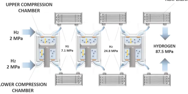
Nowadays, linear compressors are especially used for electronics cooling, thanks to their own capacity in maintaining low temperatures inside chips and miniature devices (100). Nevertheless, the Southwest Research Institute (Texas) investigates a novel concept to enhance their applicability for high-scale hydrogen applications, consisting in driving a permanent magnet piston inside a hermetically-sealed compressor cylinder through electromagnetic windings (82). The main purpose is to obtain hydrogen at around 87.5 MPa through a system consisting of three linear compressors combined with a water-based cooling loop (Fig. 6). Table 3 gathers the main characteristics of a hydrogen linear compressor.
Fig. 6 – Scheme of a three-stage linear compressor system for hydrogen applications (After (82))
19 Table 3 – Hydrogen linear compressor
LINEAR COMPRESSOR Pin [MPa] Pout [MPa] Flow [Nm3/h] Application Efficiency [%] Broerman et al. (82) 2 86 - 95
(3 stages) > 112 - Research studies > 73
*
Advantages - Compactness - High reliability - High efficiency
- Low vibration and low noise - Long operation life
- Only few moving parts
Disadvantages - Necessity to control the piston displacement - Necessity to operate at resonant conditions - Oscillating pressure
*isentropic
2.4 Liquid compressors
Liquid compressors are particularly suitable for hydrogen applications (49). They are positive displacement devices (101) using liquids for directly compressing a gas (102), working in the absence of mechanical sliding seals. They are widely recognised to achieve inexpensive compression, since they are able to ensure a quasi-isothermal process (103–105). In fact, the liquid and the gas are compressed together, but since the liquid has a higher density as well as a higher heat capacity, the heat generated by compression is efficiently absorbed by the liquid and by the surrounding walls of the compression chamber. In addition, the resultant thermal management through the liquid itself prevents the use of external heat exchangers, thus reducing the cost of the overall system. As a result, such typology of compression has a significant advantage over the other mechanical compressors in terms of efficiency, with values higher than 83% (102).
2.4.1 Liquid piston compressors
Like in all other mechanical compressors typologies, hydrogen confined in a closed space is directly compressed by a moving piston, which in the present devices is liquid (106).
20 Specifically, a column of liquid moves forth and back in a cylinder, compressing the gas introduced in its head. The liquid movement is driven by a pump, which in most of applications is connected to two cylinders, where a compression step continually follows an expansion step (Fig. 7).
Liquid piston compressors are especially used in the context of compressed air energy storage, in which electrical power is converted into compressed air energy at 20-30 MPa (107), and which can be used on site to power generators and turbines, or can be stored for being used later. This kind of solution is usually associated with renewable energy plants (105,108–110). Porous media can be used in order to improve significantly the heat transfer inside the compressor chamber (105,111,112). Since the liquid can flow through the open, connected pores of the porous matrix, an increase of the overall heat capacitance is achieved, limiting the temperature rise of the gas. Moreover, the presence of porous solids ensures at the same time a good seal to prevent gas leakages, eliminating potential dead volumes and increasing the efficiency (105).
21 Internal liquid-spray cooling, usually adopted in reciprocating compressors, can even be a valid alternative to further limit the temperature rise inside the compression chamber (113), as the liquid droplets provide a large surface area for the heat transfer, absorbing efficiently the heat generated by the compression process. Moreover, liquid piston compressors benefit more than the reciprocating ones from this cooling method, since the residue of the spray falls downwards to the liquid phase. However, in order to obtain an effective increase of compression efficiency, an optimal spray profile has to be determined (114).
2.4.2 Liquid rotary compressors
Liquid rotary compressors (Fig. 8) are particularly used for compressing a gas with a high liquid content (54,115,116). In this design, an impeller located eccentrically in a stator frame and composed of a series of blades extended radially from it, forces the liquid to move globally in an oscillatory manner, forming a ring compressing the gas introduced from a door placed in the rotor centre (116)(117). This kind of compressor fits very well applications implying vacuum (118), or when saturated gases have to be handled (119). However, they are not widely used because of their low overall efficiency, about 50% (116).
22 2.4.3 Ionic liquid compressors
Ionic liquid compressors were specifically developed for increasing the compression efficiency when hydrogen is used (67). Ionic liquids are low-melting point salts, hence in the molten state at room temperature (120), exhibiting good thermal and chemical stability, high ionic conductivity, fire retardance, moderate viscosity, high polarity, negligible volatility, no negative effect on human health, as well as low compressibility and superior lubricating abilities especially for high-pressure applications (121,122). They are interesting for a broad range of energy applications, e.g. in batteries, fuel cells, solar cells and thermal storage (123). When used for compression applications, by substituting the solid piston in a positive displacement device as well as in rotary configurations, the ionic liquids ensure very good performances, thanks not only to their intrinsically low vapour pressure, but also to their excellent tribological behaviour as well as to the very low solubility of most gases into them (124). Specifically, hydrogen solubility in many ionic liquids is negligibly low (125), achieving in this way very high volumetric efficiencies and high compression ratios (126).
Ionic liquids compressors for hydrogen applications have been developed in particular by the International German Company Linde (127,128). Linde ionic compressors need only eight moving units to ensure good performances, which is clearly less than in reciprocating compressors, reducing in turn the mechanical losses and improving the overall efficiency. Hydrogen is compressed up to 90 MPa in only five steps, with an efficiency that is increased thanks to the good lubricant and coolant properties of the ionic liquids. It is noteworthy that no lube oils are used so that hydrogen is not polluted; this is a great advantage especially in fuel cells applications.
Ionic liquid compressors used in hydrogen fuelling stations were proved to be a high-performance solution for the enhancement of the hydrogen value chain (128). When compared with a lubricant-free reciprocating compressor, the net capacity was indeed
23 increased from 5-11 kg/h to 8-30 kg/h, with a final pressure increased from 35-70 MPa to 45-90 MPa (127). The use of ionic liquids for hydrogen compression also ensures low energy consumption, long service life, low material costs and low noise emission. Nevertheless, the risk of corrosion remains high, causing a decrease of the overall efficiency by reducing the strength of the constituting materials and increasing the possibility of contamination by the corrosion products. Besides, an increase of the maintenance costs is to be expected. It has been found that the stainless steel AISI 316L is particularly well-suited for hydrogen ionic liquid compressors (129), preventing corrosion effects as well as hydrogen embrittlement phenomena. In addition, other drawbacks can impair the performances of ionic liquid compressors: (i) the liquid may leave the compression chamber through the discharge line together with the gas, making necessary the use of liquid traps in the gas passage (102); and (ii) a certain amount of gas can be driven in the liquid, causing cavitation phenomena in the low-pressure areas of the cylinder (104). Table 4 gathers the main characteristics of a few representative examples of hydrogen ionic liquid compressors.
Table 4 – Hydrogen ionic liquid compressors
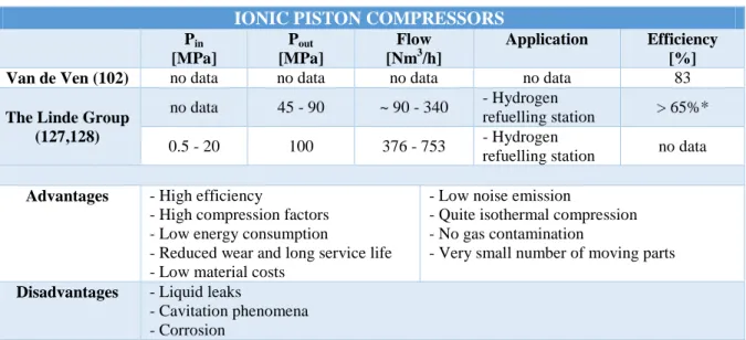
IONIC PISTON COMPRESSORS
Pin [MPa] Pout [MPa] Flow [Nm3/h] Application Efficiency [%]
Van de Ven (102) no data no data no data no data 83
The Linde Group (127,128)
no data 45 - 90 ~ 90 - 340 - Hydrogen
refuelling station > 65%* 0.5 - 20 100 376 - 753 - Hydrogen
refuelling station no data
Advantages - High efficiency
- High compression factors - Low energy consumption
- Reduced wear and long service life - Low material costs
- Low noise emission
- Quite isothermal compression - No gas contamination
- Very small number of moving parts
Disadvantages - Liquid leaks
- Cavitation phenomena - Corrosion
*this value was calculated by considering the specific energy consumption of this compressor provided in the corresponding reference (2.7 kWh/kg) and by considering the compression process as isothermal
24 3. Non-mechanical compressors
Even though mechanical compressors have been widely used for hydrogen applications, the low specific volumetric energy density affecting hydrogen in the gaseous state requires significant amounts of energy for compressing enough gas (130): the actual work of compression carried out by a mechanical hydrogen compressor is almost one-third of the amount of energy stored in the resultant compressed gas (131). Moreover, the efficiency of a mechanical hydrogen compressor is still modest in low-power applications (132). A possible solution might be storing hydrogen at cryogenic temperatures since the volumetric energy density is higher, but due to the high cost as well as to the difficult thermal management, this method is reserved for special applications only. Thermally-driven compressors have also shown to be a good alternative, as well as the electrochemical compressors.
3.1 Cryogenic compression
Cryo-compression combines hydrogen liquefaction and compression, providing a combination of benefits and challenges of both storage methods, relying on the achievement of high pressures at very low temperatures. High-pressure hydrogen is obtained by using cryogenic pumps able to reach a discharge pressure as high as 85 MPa, a hydrogen flow rate of 100 kg/h and a hydrogen density up to 80 g/L (133). Hence, instead of compressing hydrogen in the gaseous state, liquid hydrogen is pressurised (134) and stored in cryo-compression systems consisting of a pressure vessel integrated in an insulated jacket to significantly reduce the heat transfers between cold hydrogen and the exterior (135). The inner vessel is generally made of carbon-fibre-coated metal, the intermediate vacuum space filled with sheets of highly reflective metallized plastic, and the outer jacket made of metal (136). A cryo-compressed hydrogen vessel fuelled by liquid hydrogen at high pressure offers
25 several advantages when compared to the traditional cryogenic tanks storing liquid hydrogen at ambient pressure, such as (i) lower evaporative losses due to short periods of inactivity or low driving distances, and (ii) smaller ullage spaces (up to 20%) to prevent dangers (137). This solution allows storing 2-3 times more fuel than using conventional ambient-temperature compressed vessels (138), i.e., a lower pressure is necessary to store a given amount of hydrogen. Whereas a pressure of 75 MPa is indeed necessary for storing 4.1 kg of hydrogen in 100 L at room temperature, a pressure of only 15 MPa is required to compress the same amount when the temperature is decreased to 77K (139) (140).
The design of such hydrogen-compressing system is very sophisticated, and consists into several modular elements sequentially arranged, i.e., a tank storing liquid hydrogen at low pressure, a cryogenic pump, and cryo-compressed vessels. Liquid hydrogen is fed to a cryogenic pump through vacuum-insulated piping. Then, the cryo-pump leads liquid hydrogen to the desired pressure value. Vaporisers can be used downstream of the cryogenic pump in order to obtain high-pressure gaseous hydrogen (141), as shown in Fig.9.
26 Hydrogen cryo-compression systems have more than twice the volumetric efficiency of a mechanical system (142). Nevertheless, the low temperatures require a continuous monitoring of the system thermal insulation, with a resulting higher system complexity aimed to control the vacuum stability (136,143), which represents the greatest technological challenge (136). The performances of such a system strictly depend on the geometry of the pressure vessel, as well as on the materials used. Several improvements were achieved during the last years, such as a significant compaction of the overall system package (139) or a reduction of the liner thickness, from 3 to 1.5 cm (142). Further improvements could be also achieved using lighter-density alloys as shell materials: a nominal hydrogen storage capacity of 9.2 wt.% was reached when an Al alloy was used.
Cryo-compressed hydrogen vessels have been tested especially for automotive applications, e.g. the hybrid ICE/battery Toyota Prius and several prototypes proposed by BMW (144,145). Hydrogen cryo-compression meets DOE 2017 system targets, thus fostering the development of cryo-compressed hydrogen storage for automotive applications (146). Moreover, hydrogen cryo-compression allows reaching 70 MPa, necessary for the development of an efficient hydrogen refuelling station (31). Supercritical cryo-compressed hydrogen storage for fuel cell-powered electric buses was also investigated (147). Using a 50 MPa cryo-compressed hydrogen vessel, an improvement of 91% in gravimetric capacity was achieved. A reduction of 46% in carbon fibre composite mass and 21% lower system cost than in the case of a 35 MPa composite vessel filled with gaseous hydrogen were also obtained (147). The cost of a 35 MPa hydrogen vessel is around 17$/kWh while the cryo-compressed counterpart costs around 14$/kWh. Nevertheless, the cost of a cryogenic hydrogen storage system still remains much higher than the DOE targets (4$/kWh) (139).
Beside the aforementioned advantages of hydrogen cryo-compression over the traditional compression, it is well known that the energy cost necessary to liquefy hydrogen is a strict
27 limitation, being 30% of the chemical energy stored based on the hydrogen lower heating value (LHV) (138). Another important drawback hindering the use of cryo-compressed vessels, especially in automotive applications, is that they are not yet able to ensure a 10 year-long vacuum stability. Such a level of vacuum stability can be only achieved by using metal surfaces baked at high temperature, whereas the inner pressure vessel is commonly made of composite materials. One technical solution might be the adoption of custom getters (136). Table 5 gathers the main characteristics of a few representative examples of hydrogen cryogenic compressors.
Table 5 – Main features of hydrogen cryogenic compressors CRYOGENIC COMPRESSORS Pin [MPa] Pout [MPa] Flow [Nm3/h] Application Efficiency [%] Kunze et Kircher (148) no data 30 > 1000 - Hydrogen refuelling station no data Linde (127) no data 35 - 90 > 1000 - Hydrogen refuelling station
- Fuel cells vehicles
no data
Advantages - High hydrogen density - High volumetric efficiency
- High gravimetric and volumetric capacities
Disadvantages - Low temperatures
- Difficulty in managing thermal insulation - Energy cost for liquefaction
- Vacuum stability
3.2 Metal hydride compressors
Metal hydride compressors ensure an efficient hydrogen compression without any moving part, whether using solid or liquid pistons, or diaphragms. They are also well-known as “thermally powered” compressors, since they are based on the properties of hydride-forming metals, alloys or intermetallic compounds, to absorb and desorb hydrogen simply by means of heat and mass transfer in the reaction system (149). This technology is specific to hydrogen applications: in fact, it was first demonstrated in the 1970s as a hydrogen refrigerator (150) and as an innovative method for storing hydrogen. During the last years, it has been used for
28 different hydrogen applications like compression, storage, cryogenics and actuators (151). Several studies focused on the use of metal hydrides for hydrogen compression, and were thoroughly reviewed elsewhere (152).
A metal hydride is a binary combination of hydrogen and a metal (elemental metal, alloy or intermetallic compound) in which the latter reacts reversibly with hydrogen (59):
(2)
Hydrogen absorption is an exothermic process, accompanied by the release of heat (Q in Eq. (2)), while desorption is endothermic so that hydrogen is released only upon supply of heat. A metal hydride hydrogen compressor essentially consists of a stainless steel tank containing the metal hydride and a heat source/sink (Fig. 10). Different tank designs were developed, and were reviewed in-depth elsewhere (153). The tubular configuration is largely adopted as it facilitates mass and heat exchanges. It consists in a narrow central artery, aimed to distribute hydrogen inside the reactor, and an annular space between the artery and the tank wall where the metal hydride is packed. When low-pressure hydrogen is introduced into the metal hydride tank through the central artery, it is spread in the metal hydride bed and hydrogen exothermic absorption occurs. Absorption starts at low temperature, and continues until the equilibrium pressure is equal to the supply pressure. In order to evaluate the equilibrium pressure at which both metal-hydrogen solution and hydride phase coexist, the Pressure-composition (P-c) isotherms, specific to a given hydride-forming material, are used (154). Once the equilibrium pressure is reached, hydrogen desorption can be carried out by supplying heat to decompose the metal hydride. Desorption produces the increase of the hydrogen pressure to the desired discharge pressure, and allows reaching a new P-c equilibrium. In brief, hydrogen compression is the result of sequential cooling and heating of the metal hydride structure at it is controlled almost entirely by heat transfer (155). Natural air
29 convection or forced air are generally used to manage the heat transfer inside the reactor, but an extensive number of applications are also based on water- or oil-cooling systems (152). Heat exchange can be driven through the external surface of the wall; the outer diameter of the tubular reactor is generally not larger than 30 mm in order to allow an efficient heat transfer in the radial direction (153). Correspondingly, a height to diameter ratio larger than 10 is used to hold a satisfying amount of metal hydride. Thus, it is possible to realise a thermally-driven compression with a very simple design and operation, without moving parts as well as without problems related to wear, noise or intensity of energy used. Moreover, it is not necessary to use large volumes, resulting in compactness and an easier integration within infrastructures and hydrogen plants (156). With a high-temperature heat source, the achievable discharge pressure can be 3 to 10 times the supplied one (157) with volumetric efficiencies up to 93% (158). Nevertheless, with such compressors, known as single-stage metal hydride compressors, the discharge pressure achievable by using moderate temperatures is not very high (159,160).
Hydrogen users, such as ammonia producers or some laboratory practices, as well as the innovative hydrogen refuelling plants, require hydrogen at 70 MPa (161). Several studies (162,163) showed that such a goal is achievable by using a multistage hydride compressor, in which a series of coupled modules containing metal alloys with different equilibrium hydrogen pressures at the same temperature promotes the cyclical absorption and desorption of hydrogen under specific thermodynamic conditions, allowing a progressive increase of the outlet pressure (156). The development of such compressors requires a trade-off between the pressure level and the overall efficiency to be reached (157).
30 Fig. 10 – Scheme of a single-stage metal hydride hydrogen compressor
The selection of well-suited hydride alloys (Fig. 11) is fundamental in order to have an efficient hydrogen compression. Several requirements have to be satisfied, like high disassociation pressures at moderate temperatures, high hydrogen storage capacity, fast kinetics, easy activation (i.e., treatments to optimise sorption capacities and kinetics in order to obtain good charge-discharge cyclability), and low costs (160,164). The Ni-based AB5
hydrides have proven to be an appropriate option, as they are not very expensive and exhibit good performances, especially at moderate temperatures. LaNi5 (150) was the first Ni-based
AB5 alloy used for hydrogen compression; when nickel was partially substituted by
aluminium, the storage capacity increased (163). Although it is really difficult to achieve pressures higher than 10 MPa by using only a single-stage hydride compressor (165), it is possible to achieve 70 MPa by adopting a double-stage configuration (163). Ti-based AB2
hydrides are also widely used for hydrogen compression, being able to achieve 70 MPa through a multistage configuration (162), ensuring higher compression factors and good storage properties (157), even though they require extremely low temperatures to operate (166). Vanadium-based BCC solid solution alloys have also shown promising hydrogen
31 absorption capacities with fast absorption / desorption kinetics at ambient temperature: Ti-V based alloys reached 65 MPa at moderate temperature when small amounts of niobium and manganese were added in the alloy structure (167)(168). Finally, AB-type intermetallic compounds, especially TiFe-based alloys, exhibit advantages over the AB5 materials in terms
of hydrogen storage capacity, low cost and abundance of raw materials for manufacturing them, but they are affected by poor activation behaviour, thus requiring specific thermal treatments in order to reach high discharge pressures (169).
Fig. 11 – Crystal structure of alloys and corresponding hydrides used for metal hydride hydrogen compressors (reprinted from (152) with permission from Elsevier).
The real advantage of metal hydride compressors is that the energy feeding the system can derive from waste industrial heat instead of electricity (170), or be of renewable origin, mainly solar (171). These features can significantly decrease the system (or OPEX) costs with
32 respect to those of mechanical compressors, considering that electricity is certainly more expensive (60). High-pressure hydrogen can be obtained in situ from water by connecting metal hydride compressors to the outlet of an electrolyser, recovering in this way the electrolyser heat losses (172). In reality, high-pressure electrolysis is not feasible because hydrogen can cross the membrane of the electrochemical cell, reacting with oxygen and decreasing the performances of the system (173). For this reason, the maximum operating pressure of an electrolyser is 13.8 MPa, and the use of a compact metal hydride compressor downstream of an electrolyser can be a valid solution to reach higher pressures. Hydrogen refuelling stations is another interesting application of metal hydride hydrogen compressors, strengthened by the rapid development of fuel cell vehicles during the last years. The latter application is feasible due to their high volumetric storage capacity, environment-friendliness, and a larger compactness compared to other typologies of compressors. Thus, a hydrogen metal hydride compressor was integrated in a hydrogen refuelling station of fuel cell-powered forklifts by the HySA Systems Competence Centre in South Africa (174). Finally, metal hydride hydrogen compressors can represent a great advantage for industrial customers producing low-pressure hydrogen, as they can obtain high-pressure hydrogen by connecting their pipelines to a compact thermally-driven compressor (175).
The efficiency of a hydrogen metal hydride compressor is generally below 25% at 423K (152) and strictly depends on the compression rate and on the amount of heat provided to the system; it can be defined as the ratio of compression work to heat input. The energy losses related to heat transfer, the heat supplied to the system for hydrogen desorption, and the energy related to cooling must be considered in the evaluation of the efficiency. For instance, if a heat pump is used for cooling, the overall energy consumed in the compression process increases, hence a resultant decrease of efficiency. An efficiency of 7.3% was calculated for a hydrogen metal hydride compressor with a pressure ratio of 8.76 and a desorption temperature
33 of 368 K (158). On average, the efficiency of a hydrogen metal hydride compressor does not exceed 10%, as shown in Table 6. Using heat recovered from an electrolyser or higher desorption temperatures could improve the compression efficiency (176). The efficiency of hydrogen metal hydride-based compressors are particularly affected by the limited heat transfer between the heating/cooling fluid and the metal hydride alloy (177). This is due to the low thermal conductivity of the metal hydride bed, offering good performances only when its value is increased up to around 6 W/m/K (164). A copper coating of approximately 1-2 µm could be applied at the surface of the metal hydride powder in order to improve the thermal conductivity (178). The system efficiency can be also affected by impurities like oxygen, carbon monoxide, sulphur dioxide, methane and nitrogen in the feeding gas, decreasing both the hydrogen capacity upon cycling and the absorption kinetics (179).
The design parameters of the reactors, such as thickness, dimension and combination with the cooling system, can be optimised in order to achieve good performances of a metal hydride compressor. In particular, the bed thickness and the void fraction in the metal hydride bed are important parameters to take carefully into account in the design of thermally-driven compressors. In fact, during the absorption process, an expansion of the solid bed occurs when hydrogen penetrates inside the metal hydride. Therefore, continuous absorption and desorption cycles may pulverise the alloys into small particles, because of the repeated expansion and contraction of the material’s volume. If an irreversible deformation occurs, the hydrogen capacity of the hydride may be significantly hindered, with a resultant decrease of the overall efficiency (162). Moreover, it is important to guarantee a high hydrogen filling of the structure, in order to avoid the presence of empty space, being detrimental for the productivity. Nevertheless too high filling densities, exceeding 61% of the material density in the hydrogenated state, can lead to structural deformation or even to the damage of the hydride container (180). The common way of mitigating this negative effect on the metal
34 hydride compressor is to impose a large length to diameter ratio, or to place the container horizontally. It was also proved that a layer of oxides usually covers the surface of the hydride as a result of an improper process of preparation of the alloys (181). The current efforts for optimising the design as well as the manufacturing technology might result in a significant price decrease (152). Table 6 gathers the main characteristics of a few representative examples of metal hydride hydrogen compressors.
Table 6 – Metal hydride hydrogen compressors
METAL HYDRIDE COMPRESSORS
Pin [MPa] Pout [MPa] Flow [Nm3/h] Application Efficiency [%]
Madaria et al. (171) 1 3.5 no data no data 6.07
Shmal’ko Y.F. et al. (182,183)
0.3 15 10 - Argon purification for Lviv
Chemical Plant 4.48
1.5 400
(cryogenic) 0.24
- Synthesis of metal hydrides, deuterides and tritides - Modification of plastic and magnetic properties of metals
2.44
Da Silva E.P. (184) 1 10 0.42 - Compression of high-purity
hydrogen 4-7
Solovey et al. (161) 1 15 - 30 0.7 - 1.4 - Ammonia production 0.92 - 3.9
Bhuiya et al. (185) 1.3 - 4 10-15 no data - Efficient hydrogen storage at
room temperature no data
Lototskyy et al.
(186) 1 20 1 - Industrial applications 1.65
Yartys et al. (175)
1 20 10 - HyNor Lillestrom refuelling
station (Oslo) no data
0.3 20 5
- Industrial applications (Eskom Holdings Ltd. South Africa)
no data
Hu et al. (187) 2 35 0.19 - Fuel cells vehicles no data
2 38 0.28 - Fuel cells vehicles no data
Kelly et al. (173) 14 41 no data - Hydrogen refuelling station
and Fuel Cells vehicles 3 - 5
Wang et al. (159) 4 45 1.2 - 2.4 - Fuel cells on-board storage no data
Wang et al. (162) 4 70 no data - Hydrogen refuelling station no data
Li et al. (163) 5 70 2 - Lightweight hydrogen
storage vessel no data
Pickering et al.
(167) no data 65 no data - Automotive applications no data
Advantages
- Thermally-driven compression - Absence of moving parts - Compact design
- Safety
- Absence of noise - High-purity hydrogen
Disadvantages
- Limited heat transfer
- Necessity of using appropriate alloys - Low efficiency
- Weight
- Cost of container/ compression elements
35 An electrochemical hydrogen compressor, also known as “electrochemical hydrogen pump”, is an innovative device that can be used to compress hydrogen with high recovery ratios, up to 95% (188), and in applications requiring low gas quantities at very high pressures. It is based on the same basic principles as those of a proton-exchange membrane fuel cell (PEMFC). Low-pressure hydrogen (pa) is fed to the anode of an electrochemical cell,
where it splits into protons and electrons, according to the reaction:
(3)
Protons flow electrochemically through a solid polymer electrolyte, whereas electrons follow an external path, which is the electrical circuit controlled by the potential differential supplied to the system. Once protons and electrons reach the cathode, they recombine to form hydrogen molecules again, with a resultant increased pressure, pc (Fig. 12):
(4)
This process continues as long as the driving force provided by the current, i.e., the electric energy supplied to the system, exceeds the internal energy of the system itself (189). The oxidation rate at the anode, i.e., the rate at which low-pressure hydrogen is converted into protons, can be evaluated from Faraday’s law (190):
(5)
where n is the inlet hydrogen flow in [mol], F = 9.648 104
C/mol is the Faraday constant and I is the current [A]. Eq. 5 clearly shows that the higher is the current supplied, the higher is the rate at which protons are transferred from the anode to the cathode.
36 Fig. 12 – Scheme of an electrochemical compressor
The performance of an electrochemical compressor is governed by the Nernst equation, which gives the relationship between the achievable pressure ratio and the voltage supplied to the system:
(6)
where E0 is the cell potential at standard conditions (considered 0 in the case of an
electrochemical compression), R is the universal gas constant, T is the absolute temperature, and F is the charge of 1 mole of electrons. The discharge pressure strictly depends on the electrical voltage supplied to the system: the higher the latter, the higher the pressure at which protons are reduced at the cathode. In other words, the Nernst potential indicates the minimum amount of voltage to apply to the system for achieving the desired compression ratio. According to the Nernst equation, a potential differential of only 0.054 V is enough to increase the hydrogen pressure from 1 to 70 MPa at room temperature (191). Nevertheless, an electrochemical compressor is affected by several voltage losses, thus a higher voltage than
37 the Nernst potential must be supplied to the system in order to reach the desired discharge pressure. These voltage losses are the activation overpotentials and the Ohmic losses (188), as shown in Eq. 7:
(7)
ηa and ηc are the anode and cathode overpotentials, which can be defined as the potential
losses due to the reactions kinetics (192). Actually, both hydrogen oxidation and reduction reactions are highly reversible in an electrochemical compressor, thus the overpotential contribution to the cell voltage can be considered as negligible (188). Finally, the last term of Eq. (7) is clearly related to the Ohmic losses, and the term r incorporates the electrical resistances of membrane, electrode and cell hardware. Actually, the electrical resistance of the membrane is the main factor affecting the performance of a hydrogen electrochemical compressor (193), and it is strictly related to the proton conductivity of the polymer electrolyte membrane. Thus, in order to decrease the Ohmic losses, a high ionic conductivity of the membrane is required (194). High mechanical and chemical stabilities, as well as resistance to high temperature are other crucial features.
The membrane currently used in hydrogen electrochemical compressors is based on perfluorocarbon sulfonate polymers, e.g. Nafion® 117 (132,188), which allows the selective transfer of one or few cationic species, protons in the case of a hydrogen electrochemical compressor. In order to ensure optimum compression performances, a good hydration level of the membrane is required, since its protonic conductivity is enhanced while the membrane is saturated with water. Hence, protons cross the membrane in the hydrated form H2n+1On+,
where n is the electro-osmosis coefficient. This strict requirement highlights the importance of an efficient water management inside the system. In fact, unlike in proton-exchange membrane fuel cells, water is not a reaction product in an electrochemical compressor, so it is
38 necessary to develop a control system monitoring the humidity level on both sides of the cell, e.g. by addition of water to the anode compartment, thus preserving the optimal hydration degree of the membrane (195). Besides, the use of Nafion® as proton-exchange electrolyte in an electrochemical compressor, as well as in other PEM devices, implies operation at low temperatures, typically below 353 K (196), since higher temperatures can affect the stability of the perfluoro-sulfonate polymer. Nafion is also quite expensive (197), and difficult to dispose because of its intrinsic acidic nature, thus requiring specific post-treatments (198). For these reasons, several alternative materials were investigated in order to substitute Nafion®. A sulphonated poly(ether ether ketone)/crosslinked poly(styrene sulphonic acid) SPEEK/CrPSSA semi-interpenetrating polymer network membrane was investigated (199). Such a membrane exhibited very high proton conductivity and was cheaper than Nafion® membranes. However, the energy efficiency was lower than that commonly obtained with Nafion®. Hydrogen-sulphated fullerenol was also tested in a system consisting of a first electrochemical stage followed by a LaNi5 metal hydride compressor reaching hydrogen
pressures up to 1 MPa (200).
Both reactions (3) and (4), i.e., the hydrogen oxidation at the anode and its reduction at the cathode, respectively, are catalytically-driven processes, and take place on the “three-phase boundary” points (194) where the electric circuit, the membrane and the gas phase are in intimate contact. Since the rate of the single electrochemical reactions can significantly affect the performance and the efficiency of electrochemical compressors, the membrane, the electrodes and the catalyst can be assembled in membrane electrode assembly (MEA) to speed up the electrochemical process, in which metal nanoparticles are dispersed in a solid electrolyte matrix. Noble metals, especially platinum, platinum-ruthenium and palladium are selected (194) because of their excellent catalytic properties. The proton-exchange membrane (PEM) technology adopts MEAs consisting in 0.1-0.2 mg/cm2 platinum-based catalyst