HAL Id: hal-02577075
https://hal.inrae.fr/hal-02577075
Submitted on 5 Oct 2020
HAL is a multi-disciplinary open access
archive for the deposit and dissemination of
sci-entific research documents, whether they are
pub-lished or not. The documents may come from
teaching and research institutions in France or
L’archive ouverte pluridisciplinaire HAL, est
destinée au dépôt et à la diffusion de documents
scientifiques de niveau recherche, publiés ou non,
émanant des établissements d’enseignement et de
recherche français ou étrangers, des laboratoires
A mobile platform with a robotic arm working in a
semi-structured environment: two basic contributions
Nicolas Clavel, Pierre Thompson, Francis Sevila, René Zapata
To cite this version:
Nicolas Clavel, Pierre Thompson, Francis Sevila, René Zapata. A mobile platform with a robotic arm
working in a semi-structured environment: two basic contributions. 12th Triennal Wold Congress
of the International Federation of Automatic control, Jul 1993, Sydney, Australia.
pp.493-500,
�10.1016/S1474-6670(17)48776-3�. �hal-02577075�
Copyright © IFAC 12th Triennial World Congress, Sydney, Australia, 1993
A
MOBILE PLATFORM WITH A ROBOTIC ARM WORKING
IN A SEMI-STRUCTURED ENVIRONMENT:
TWO BASIC CONTRIBUTIONS
N. Clavel*, P. Thompson*, F. Sevila* and R. Zapata**
·CEMAGREF, BP. 5095, F-34033 Monlpe/lier Cedex I, France
··URMM. Place Eugene Balaillon, F-34095 Monlpellier Cedex5,France
Abstral't. Envisioned robots for rural and outdoor activities will navigate in semi-structured environments and execute intelligent tasks with the robotic actuators they carry. Most actions will have to be done avoiding a stop of the mobile. Two problems generated by such a concept of machine are addressed in this paper: how to navigate in a partially known and evolving environment, and how to comhinc rohotic anll motions with its supporting mobile platfonll oncs. Tests are made on the specially designed and huilt agriculturalmohile rohot OTOMAT.
Key Words. Control Applications. Local Navigation. Artificial Potential Fields
1. INTRODUCTION
Rural outdoor environments, like forests, agricultural open fields, orchards, or golf courses will need in the future, autonomous machines to execute robotic tasks in an adaptive way. Performing such actions and staying profitable, human and environment friendly, means that efficiency, rapidity and security will be crucial. In particular:
*
Navigation method will have to be flexible enough to help finding an appropriate path in an environment which is only partially known. and where non-announced obstacles can appear.*
Robot actuators, using machine vision as their main reference information, will have to execute sophisticated tasks, while their carrying platform will stay moving on an appropriate trajectory. Combination of motions and references in the 3 involved coordinate systems (machine vision-robot arm-mobile platform) has to be made appropriately. State of the art methods have been found for both problems, however they were not entirely solving them. Complementary theoretical developments have been made, they are described in chapter 4 and 5 of this paper. To implement and test these modified methods, a complete mobile robot has been specially designed and built, this system is described in chapter 2.2. DESIGN OF A SPECIFIC MOBILE ROBOT: O'TOMAT.
A complete mobile robotic system, called O'TOMAT, able 10 work alone, executing tasks in a semi-stmctured environments, has been developed (see figure I). Its purpose is to validate the various methods proposed in the research, on a flat floor (2 dimensional problem).
Fig. I. Overall vue of robot O'Tomat
The four wheel mobile platform (MP) of this robot has a steering control obtained by differential rotation between the 2 electrically powered rear wheels. the 2 non-powered front wheels being free to rotate. Odometers are mounted on the rear wheels. It advances at speeds up to Im/s.
A target detection camera is rigidly mounted at the front of MP.
be task in their known The robotic arm has 2 rotational joints for sphcrical positioning, and thc mouvcmcnt to thc targct for task cxecution is obtaincd by a telescopic dcvice.
The wholc systcm is small and light (50kg). A built-in central PC -l8GDX type board managcs a VPIX (BYTECH) framc grabbing board, and 5 mono-axle PELLENC-MAX control boards (I for each electrical motor:2on MP and 3 on the manipulator). Battery mountings provide clcctric energy to thc whole system.
The system has been tcsted in laboratory with simulated workspace environments as mentioned below.
3. NAVIGATION IN A SEMI-STRUCTURED ENVIRONMENT
3.1. The artifcial potential field mcthod "APF". Mobile robot navigation can be made using either global or local methods:
*
With global navigation methods, optimal trajectories (Brooks, 1(83) and manoeuvring (Pommier, 1(91) can be computed, but they imply the knowledge of the complete working environment. This means that integration of unknown obstaeles, or changing motion goal during the mobile robot mission is time consuming, and not always feasible.*
The local navigation method allows incidental events but not global optimisation.Mobile robots for mral environments will oriented, dedicated to execute tasks scattered environment In an only partially arrangement. Such tasks can bc:
*
curing damaged trees in a forcst, or*
spraying chemical on weeds among growing vegetables,or
*
harvesting unevenly matured fmits, or*
pmning landscaping bushes in a golf course or in a leisure parketc.
Most of these applications mean that tasks are decided and determined when the robot is arriving near the future task location, by some detection means (mainly based on machine vision).
For such applications, global navigation methods can be applied only for a very rough definition of the robot trajectory in its environment. Only a local method can allow a local task definition to be takcn into account for the trajectory computation.
In this paper. we will address a particular local navigation method based on the use of Artificial Potential Fields ("APF").
First developed by Khatib (Khatib 1978, 1(85), the navigation algorithms using APF have interested many researchers because of their main advantages,
compare to other proposed methods: low algorithmic complcxity, integration of robot inertial characteristics, natural understanding of the phenomena and simple computation for on-machine implementation.
In APF, navigation is made by solving the following differential eCluation:
with: M(x): Inertial Matrix Fc: Centrifugal Force Ug(x)= Ua(x)+Ur(x) Ug: Global APF.
Ua: Attractive APF (goal) Ug: Repulsive APF (obstacles)
Fig. 2: Example of global APF.
The trajectol)' of the robot tends to follow the maximum negative slope between its starting point and its target ("deep" value of the gradient), avoiding obstacles (represented by peak values of the gradient) Among various inherent limitations of the APF method (Koren and Borenstein 1991), the major one for the type of conditions found in the semi-structured environment applications, is the non-convcrgence induced by the presence of local minima in the workspace description. In some cases, generally in front of obstacles, the gradient slope followed by the trajectory arrived in basin of low gradient, from which no descending slope can extract it,
A solution to this basic problem has to be found that respects all the advantages of the APF method. A new method is proposed in this paper which solves the problem. The method allows also to compute wcll-shaped trajectories and permits in some cases to overcome saddles in the gradient surface, which appcar bet\\een obstacles close to each others.
3.2. The local minima problem in the "APF" potential fields
Some solutions have already been proposed to solve this problem. We can separate them in two classes: 1)those trying to modify the APF original method to avoid local minimum (Khoditscheck 1988, Megherbi and Wolovitch 1992, Noborio 1989). Khoditscheck defines a reference space without local minimum and tries to find an homeomorphism with the real workspace. Megherbi uses the complex variable and the conform transformations to solve the case one goal/one obstacle. Noborio builds directly the force field acting on the robot, using geometric criterion's on the obstacles boundaries.
2) those, which use the original APF method, but tend to extract the robot from the basin of attraction of the local minimum where the trajectory has converged. (Barraquand 1989 and Latombe 1991). Barraquand uses the principle of the thermodynamic method named "simulated annealing", and gives some increasing energy to the robot, in any direction. The purpose is to have it leave his stable state inside the minimum. Latombe, having a global numerical representation of the workspace, fills the local attracting domain.
The method proposed in this work should be classified in a third class, in the sense that it uses basic APF method in its continous form. Itis applied continuously, all along the trajectory (but the goal) without waiting for local convergence.
3.3. Our solution: systematic local deformation of the "APF"
The general idea of this method has been numerically developed in (Clavel 1992/ I, Clavel 1992/2). It is based on the systematic addition of a complementary local APF to the global one, designed to destabilize and extract the trajectory from any occurring minimum:
Destabilizing a minimum.
The way to destabilize a local mInimum is to transform it into a local maximum. The study of the stability is made by using a Lyapunov function, built with the global APF as a basis. Thus neglecting the kinetic energy of the robot, the destabilisation condition we obtain is stronger, depending only on the force field topology.
In the local domain D of the basin of attraction of this local minimum:
D = { x / ~(x,t) -> xmin when t -> oc } with~(x,t)the flow associated.
The built Lyapunow function is the following: L(y)= Ug(y) - Ug(ymin)
with ymin= x - xmin
We know that the flow associated to the system follows the decreasing values of the APF, so the ones
of the Lyapunov function. We have shown in (Clavel 1992/1) that if we add the local APF to Ug:
P(x)= F [ x , xmin ]
with F: a continuous, positive, finite, scalar decreasing function calculated with the origin xmin.
The destabilizing condition on P(x) at the point xmin is:
slope (P)> -slope (Ug)
Extracting the robot from the local attracting domain.
After the destabilization of the local minimum, the robot has to be pushed out of the basin of attraction
D.
To study this point, the Lie derivative LxO is used. The Lie derivative of a scalar function S, in x with respect to the associated vector field X, is equal to the variation rate of F along the integral curve of the vector field.
To extract the robot from the local attraction of D, the integral curve associated to the potential field [Ug (x) + P (x)l must follow increasing values of Ug(x). This is translated in the following condition on the Lie derivative:
The Lie derivative of the potential function [ Ug (x) ] with respect to the vector field induced by [Vg (x)
+
P(x)] must be positive.
Lx ( Ug(x) ) :-grad[Ug (x)
+
P(x)]>0 This leads to (Clavel 1992/1):slope ( P(x) )> -slope ( Ug (x) )
n/2<Angle[grad(P(x)),grad(Ug(x)] <3n/2
Generalisation to the whole motion
It is necessary to avoid to study each local basin of attraction and to wait for each local convergence. This is why these 2 constraints, of destabilization and of extraction. are applied continuously all along the motion of the mobile robot: this induce a local APF. which is added systematically to the global APF, at the current point of the trajectory. Of course for the global convergence it vanishes at the goal. It
works as if the robot is always carrying his own repulsive APF and we obtain a time varying global APF:
Utotal (x,t)= Ug(x)
+
P(x,t)with the origin of P(x,t) in the current point of the flow (~(x,tc)).
3.4. Consequences on the behaviour of the mobile robot.
The behaviour of the robot looks like the one of a passive surfer always followed by his wave. The local APF reinforces the general motion direction given by the static global one.
step2
Fig. 3. 2-dimension representation of the robot behaviour when passing through a local minima under local APF influence.
In this example, robot behaviour follows 3 steps: step I: The robot is following the decreasing values of the global APF.
step 2: The robot arrives at the local minimum and the local APF destabilize it.
step 3: The robot "climbs" the increasing values of the global APF, thanks to the energy of the local one.
step 1
current poi nt
step3
~
,i-'~~:". :"~60M.
±fiI1iHUlllillILWJsr··
~
'-Fig. 5. This is the basic case: one obstacle between the start and the target. Compared to the examples shown in figure 4, the oscillations phenomenon have been erased by an appropriate choice of APF functions, obtaining a well shaped trajectory.
Figure 6 and 7: In these cases of multi-obstacle avoidance, the proximity of the obstacles induces saddle shapes of the global gradient between the obstacles and induces also various minima. The space between obstacles is sufficiently large to allow the robot to pass through.
without the wave
I -
.
'r-
-~1---'
1
---
~.
, If
-
--~--'--l-
-+-t
-.-., ·1'with the wave
~.)tt'~!,lflll"I"IL'"""=fitGO"L.
EE3!1IDIIi !Ill!Ill!111111 - fj)
(i}
Fig. 6. The saddle gradient between the two first obstacles does not change the trajectory of the robot: it has enough space to pass through straight ahead.
I
- ---tJ
..--0
I-.
.
0->IIIItpoiaL +-> IlUJd.Fig. 4. An example of local APF action when the trajectory meets minima in front of obstacles. 3.5. Experimental results.
Simulation.
The figures 5, 6, 7, 8 show the results obtained by applying the local APF method in a computer simulated situation. The obstacles are designed using super ellipsis equations which allow very different shapes with few parameters. We can model the cross to the square via the ellipsis. A study of the obstacle shape influence can be found in (Clavel 1990).Ithas to be noticed that, for all these examples, the attractive, the repulsive and the wave shaped local APF have the same values. We do not need to change them with respect to the environment configuration.
Fig. 7. The direction of the motion is changed in order to avoid the obstacles during the overcoming of saddles betwecn the various obstacles. The robot follows the lcast repulsive way.
~::~c.S,.o
..
$
,.; ; I!i
.,' <I'
<*'
Fig. 8. The distances between the obstacles are not sufficicnt for the robot to pass through. Itavoids the five obstacles as it would have done for a equivalent
Experiments with the mobile robot OTOMAT. A set of typical cases of semi-stmctured environments have been arranged for the robot to find its trajectory through. Any change in the workspace configuration, for instance going from one testing configuration to the next one by changing starting point, target and obstacles number and positions, is obtained by simple reshaping of the gradient function using a limited number of parameters, thanks to the potential of the general APF method of navigation. This is confirming the potential of APF navigation method for on machine real time implementation.
However, with the global APF navigation method, the robot ability to find its trajectory is dramatically low in the type of semi-stmctured workspace environments used for the tests, where minima types of situation are numerous: applying the local APF continuous wave principle has allowed the robot navigation system to solve most trajectory problems. Navigation is always complemented with local conditions parameters: this allows the real time management of unpreviewed events.
Actual behaviours of the robot, using the local APF wave to determine on-board the trajectory have been similar to the simulation ones as shown above in figure 4 to 8. An average precision of 25 cm has been obtained for trajectories of IOm long.
Compare to the normal global APF, the algorithm complexity is severely changed. The computation cost is just increased by the time dependent APF force computing. The navigation software is adapted to on-board real time computation.
Limitations have been found on 2 aspects during these experiments:
*
the actual robot trajectory was not continuous enough, due to the limitation of the applied method in taking the robot non-holonomy into account.*
the target is attained at a certain precision: but the orientation of the Mobile Platform when approaching the target, in order for the task to be appropriately executed, has not been considered.The latter point has a major importance for the next aspect which is addressed in this paper.
4. COMBINATION OF ROBOT ARM / MOBILE PLATFORM MOTIONS
4.1. An "On-The-Go" task action
An appropriate Mobile Platform (called below MP) navigation allows to pass from a starting point to the "MP final point" passing through different "MP target points" in the outdoor environment (MP target points might be trees or bushes, for instance). The MP should stay moving on an appropriate trajectory near the "MP targets", while robotic actuators carried
on board of the MP, have to execute sophisticated tasks on the different "MP targets".
These actuators work on task targets called "M target" (leaves, fmits, branches for instance) which are positioned inside the "MP target" (trees, bushes, etc.). The "M targets" are defined through the use of an on-board-MP machine vision system.
Combination of motions and references in the 3 involved coordinate systems (machine-vision, robot-arm, mobile-platform) have to be made appropriately for the task to be executed "on-the-go" of MP. Most industrial mobile robots apply the tasks they are des'igned for, only when they are stopped (Dubowsky and Vance 1989). Thus, the problem of controlling a robot arm mounted on a MP to act "on-the-go" is seldomly found in the literature. However some constmction robots have been studied with such abilities like: painting, plastering, welding or surfacing robots (lira, 1988; Salagnac et aI., 1990). Generally their environment is well-known and geometrically modelized, the task and the end-effector are rather simple and, above all, these mobile platforms use their mobility to help the end-effector motion control.(Schroeder and Teutterer,
1990: Pin and Culioli, 1992)
There are also similar situations where the robot is fixed, and the task scene is mobile, like robots manipulating parts taken on an industrial conveyor. In these cases, conveyor trajectory is linear and speed is constant. This problem is also known as the "Tracking Problem" (Anderson, 1985; Espiau et aI.,
1991: Houshangi, 1990)
In this paper a method is proposed for such combination in a case considered as being a common situation in futur mral applications of mobile robotics: (Sittichareonchai et aI., 1989; Ballerin et al. . 1991 and see Fig. 9).
*
task detection and definition, is made with images grabbed through a machine vision system (calIed "camera" below), placed in front of the Mobile Platform MP: the MP trajectory has to bring the camera beside the "MP target" in an appropriate manner for the camera to detect a "M target".*
The robotic actuator is based at the rear of the MP. It works when arriving in appropriate position in front of "M larget". defined previously when the camera was in a similar position.*
the "M larget" for the task is generalIy situated inside a foliage: it is not defined by its 3-D position, but only by its "best line of approach and withdrawal" inside this foliage (line of minimum obstacles occurrence for the arm: (Rabatel et aI, 1991 and see Fig. 10).*
Since an cnd-effector will execute a task on the "M target" (cutting, spraying, detaching, etc... ), it has to be maintained close to the point of "M target", during the time of this task, although the MP stays moving on.Only the situation where the MP is moving on a flat floor is considered: MP motion is only 2-D.
le
Fig. 9. Robot with the different reference coordinate systems
4.2. A combination of reference systems
The rotational parameters of the "M target", obtained during detection by the camera, are memorized in the robot arm reference frame at the detection time as well as the actual robot position (see Fig. 9). The position of the camera reference frame, versus the robot arm reference frame has to be known exactly (Calibration of camera reference frame vs robot arm reference frame is absolutely necessary).
When the arm is brought to treat "M target", the MP has moved along a trajectory controlled by the autonomous navigation system (see Fig. 11). During this motion, the actual orientation of the robot arm inside the reference frameRr has to be known to be compared to the corrected approach angles of the target registered when "M target" has been detected. This continuous comparative positioning is necessary to control the arm motion during its approach to the target, the task process, and the withdrawal from the foliage.
Mathematical methods have been developed to combine the numerous parameters involved in the above combination of the robot arm and MP motions. 4.3. Arm versus platform motions combination According to the data from image processing, the position of the detected "M target" is on a straight line (00,<1>0), as shown in Fig. 10. To treat the target point properly and to be sure that no vegetation is blocking the way, the acceptable approach angles must be close to the detected parameters (00,<1>0). An angle of compliance of +/- 5° is allowed around this ideal line of approach. This defines a cone of approach inside the foliage (see Fig. 10. Starting point of cone is situated on the detection line at maximum penetration depth Pmax)
The strategy of motions for the picking arm includes 4 steps:
ARM MOTION 1: while the mobile platform is advancing, pre-positioning of the arm toward the "M target" optimum treatment situation.
This pre-positioning of the arm is made in order to be ready to penetrate inside the cone of approach (see Fig. 10). This is obtained by maintaining the arm direction pointed toward an intermediate point T at the base of the approach cone (see Fig. 10).
The coordinates of point Tare:
00, <1>0) = target M spherical coordinates obtain at detection time, and
pmin = minimal distance between robot and vegetation at detection time, known with a simple range sensor. (Needed because we have only the approach line to the target and not the cartesian coordinates of the M target).
The targeting of point T gives us the angular coordinates of the pre-positioned arm (00,<1>0), following the method of position calculation presented in the next chapter.
ARM M0710N 2: arm penetration inside the approach cone
When 0f is equal to 00+5°, the arm penetrates rapidly inside the approach cone by increasing its length df, following the approach line until the end-effector detects the target point M with a proximity sensor.
ARM M0710N 3: arm position control during the task
To maintain the end-effector close onto the target point M while the MP is moving, a correction of the command must be calculated using the method of ann position computation described below.
AR!vJ MOTION4: arm withdrawal
Mter task execution, the robot arm is rapidly withdrawn outside the foliage, staying inside the above defined approach cone.
~reeea~?Oo
~ t:ETB::TltN LItE Ott<
4.4. Method for position correction of the arm coordinates
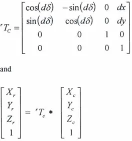
During three motions (arm motions I, 2 and 3) of the four phases described above, the instantaneous arm position in Rr (in spherical 0f,<Df,df or Cartesian Xr,Yr,Zr coordinates) has to be computed in order for the arm to target a point (T or M), which coordinates (Xc, Ye, Zc) are known in the robot reference frameRr(see Fig. 11).
Therefore we have to compute the correction matrix which is composed of the differences (dx,dy,O,O,O,d8) between the actual position of the mobile and the memorized position of the mobile at detection time This gives the correction matrix rTc:
and
cos(d8)
sin
(d8)
o
o
-sin(d8)
cos(d8)
o
o
o
o
1
o
dx
dy
o
1
Implementation of the method on the on-board computer has been made with no-significant problems.
The reliability of the combination of the camera/arm/MP systems has been satisfactory. On a constant speed (0.3 nlls) mobile operation, the arm tip has been precisely positioned on the target (with an average of+/- 5mm precision).
Arm and MP motions combination does correctly work, except when the MP trajectory between detection and task is out of certain boundaries compare to a regular one.
This result has to be translated in term of constraints on the navigation procedure: the MP trajectory has to follow an appropriate line along the target object (tree, bush, etc.) for two main reasons:
* first, for the camera to efficiently detect "M targets" ,
* then, for the carried robot arm to appropriately execute task on "M target".
5. CONCLUSION
Xr
Xc
~
rT
*
Ye
Zr
e
Ze
1
1
The values of (dx,dy,d8) are continuously obtained through the mobile platform trajectory measurements obtained through the readings of the MP motion sensors.
FfDlQ51TIDII I O"T
Q-oTI -df
Fig. 11. Schematic of the combination of robot arm / mobile platform motions
4.5. Experimental results
The mobile robot O'TOMAT has been used to test the above combination procedures. The tests havc been run with simulated bushes and targets.
Envisioned robots for rural and outdoor activItIes will navigate in semi-structured environments and execute intelligent tasks with the robotic actuators they carry: most actions will have to be delivered avoiding a stop of the mobile machine. Two problems generated by such a concept of machine have been addressed in this paper:
*how to navigate in a partially known and evoluting semi-structured environment: a particular local navigation method based on the use of Artificial Potential Fields ("APF") has been chosen. The major limitation of the APF method for such workspaces being undesirable minima of potential blocking the trajectory computation, a complementary method, building continuously a local wave of potential along the trajectory has been developed. Satisfactory results have been obtain on simulation. On a real robot experiment. although trajectories have been computed on-board elTiciently, robot characteristics, like non-holonomy and dimensions, are not completely taken into account. The mobile robot orientation near its motion target was not considered as a constraint for the navigation.
*how to combine a robotic arm motions with its supporting platform one, after on-board vision delection has taken place: Motions strategy and computing method allowing the combination of motions and references in the 3 coordinate systems involved (machine vision / robot arm / mobile platform) have been designed for the task to be executed appropriately "on-the-go" of the mobile platform. Tests with real robotic actions, on actual laboratory scenes and tasks, have given satisfactory resulls, except when robot trajectory between
detection and task was too irregular. Only flat floor motions of the mobile platform were considered. Tests have been made with a specially designed and built mobile robot O'TOMAT, carrying machine vision and telescopic arm, and working in flat floor type conditions.
Further researches are needed on the following aspects:
• Navigation method has to include actual robot parameters in an efficient way.
• Combination method of cameralarrn/MP reference
+
motions has to be extended to the case of 3-dimension motions of the carrying platform, which will be the most common in rural outdoor situations. • a complete linkage of the constraints of the 2 aspects addressed in this paper is needed: navigation has to ease to a certain extent task detection and execution, and combination of arm vs. MP motion has to be more robust toward MP trajectory irregularities.6. REFERENCES
Anderson, R.L.(1985). Real time intelligent visual control ofa robot.
In:Proceedings IEEE Workshop on Intelligent Control pp.
89-941985
Balerin, S., Bourely, A. and Sevila, F.(1991). Mobile Robotics Applied To Fruit Harvesting: The Case Of Greenhouse Tomatoes." In:Proceedings ofthe "Automated Agriculture For The 21 st. Century", Chicago, December 1991. ASAE, St Joseph
(MI-USA).
Brooks, R.(1983). Solving the find path problem by good represent.,tion offree space,. In:IEEE., March-April 1983.
Barraquand,1., and L.,tombe, J.C. (1989). On nonholonomic robots and optimal manoeuvring. In:Revue d'intelhgence artijicielle,
1989, 3(2).
Clavel, N.(1990). Determination et analyse des champs de potentiels fictifs utilises <I.,ns la fonction de navigation des rohots mobiles.
Memoire DEA. 1990, L.I.R.M.M. Montpellier (France).
Clavel, N.(1992/1). Local navigation by means oftime dependent artificial potential fields: the wave approach. In:Proceedings IFToMM jc september, 1992, Nagoya (Japan).
Clavel, N.(1992/2). Local navigation by means of artificial potential fields: surfing on a time dependent local deformation. In:
ProceedingsofAutomazione1992.36th annual congress of
ANIPLA, 16-18november 1992
Dubowsky, S. and Vance. E.(1989). Planning mobile manipulator motions considering vehicle dynamic stability constraints. In:
Proceedings IEEE Int. Con[ RobotiCS and Automation/989
Espiau,8.;Chaumelte, F. and Rives P.;(1991). Positioning of a robot with respect to an object, tracking it and estimating its velocity by visual servoing. In:Proceedings 1EEE Int. ConI Robotics and Automation1991.
Houshangi, N.(1990). Control ofa rohotic manipUlator to grasp a moving target using vision. In:Proceedings IEEE Int. Con[ on Robotics and Automation pp. 604-609 1990.
Jira,(1988). Proceedings Fiflh International Symposium on
Robotics in Construction, Tokyo (Japan). 1988.
Khatib. O.(1978). Dynamic control of manipulations operating in a complex environment. In:3rd C.I.SM. Udine (Italy), 12-15
Septemher1978.
Khatih. O. (1985). Real time obstacle avoidance for manipulators and mohile rohots. In:IEEE. St Louis (U.S.A.), 25-26 March
191<5.
KhodiLscheck.D. E. (1988). Robot navigation functions on manifolds with boundary. In:Advances in applied mathematics. July
1988.
Koren.Y.,and Borenstein . 1.(1991). Potential field methods and their inherent limitations for mobile robot navigation. In:IEE.E
Sacramento (U.S.A.). April 1991.
L.,tombe. 1.c.(1991). In: Proceedings Journees raisonnement
giwmetnql/e : de la perception vers ['action, LIFIA Institut
I.M.A.G .. Grenoble16-17 September 1991.
Megherbi.D..and Wolovitch. W.A.(1992). Real-time velocity
l~edbackohst<lcle <lvoidance via complex variables and conli.>nnalmapping. In:Proceedings IEE.E. Int. ConI Rohotlc.mnd AI/tomation Nice (France), May 1992.
Nodorio.11.(1989). A potential approach for a mobile point mobile roho! on,Illimpliciter potential field.IE.E.E. Tokyo (Japan).
Pin. F. and Culioli. 1.-C.•(1992). Optimal positioning of combined mohile platli.>nn-manipulator systems for material handeling tasks. In:Journal ofintelligent and robotic systems 6: 165-/8:3. 199:3: J.,.·II/wer Academic Publishers.
Ponllnier. E.(1991). Generation de trajectoires pour robot mobile non holonome par gestion des centres de rotation,PhD Thesis,
L.I.R.lvl. /o,'!ontpellier (France).20 Nov. 1991.
Rahatel. G.. Ilourely. A. and Sevila.F.(1991). Object detection with machine vision in outdoor complex scenes: the case of robotic harvest llf apples. In:European Robotics and Intelligent S)'stems Conference, June 23-281991, Corfu (Greece).
Salagna<:. 1.L. and Vinot,B.(1990). General localisation system for building roblllics. In:Proceedings ofMobile Robots Workshop,
Paris La Det;:nse (F).
Schroeder. D. and Teutlerer. W.(1990). Improved performance of a mohile manipulalor hy decoupling the motion ofvehic1e and roho\. In:Proceedings of3rd European Conference on Power ElectrOniCS Aachen Germany 1990 pp. 991-995
Sitli<:hareon<:hai. A. and Sevila, F.(1989). A robot to harvest grape."