Dynamic Analysis for an Internally Coupled Fluid/Riser System
The MIT Faculty has made this article openly available.
Please share
how this access benefits you. Your story matters.
Citation
Cheng, Yongming, and J. Kim Vandiver. “Dynamic Analysis for
an Internally Coupled Fluid/Riser System.” 29th International
Conference on Ocean, Offshore and Arctic Engineering: Volume 5,
Parts A and B (2010).
As Published
http://dx.doi.org/10.1115/OMAE2010-20193
Publisher
American Society of Mechanical Engineers
Version
Final published version
Citable link
http://hdl.handle.net/1721.1/109298
Terms of Use
Article is made available in accordance with the publisher's
policy and may be subject to US copyright law. Please refer to the
publisher's site for terms of use.
DYNAMIC ANALYSIS FOR AN INTERNALLY COUPLED FLUID/RISER
SYSTEM
*
Technip, Houston, TX, USA
** Massachusetts Institute of Technology, Cambridge, MA, USA
ABSTRACT
Risers are fluid conduits from subsea equipment to surface floating production platforms. The integrity of a riser system plays a very important role in deepwater developments. A top-tensioned riser generally consists of outer casing, inner casing and tubing. The pipes are coupled either through fluids in the annuli or through intermediate guides (centralizers) or through both. This paper investigates the dynamic analysis for such an internally coupled fluid/ riser system.
This paper first presents a theoretical formulation for a general riser system coupled with fluids in the annuli and centralizers between pipes. Hydrodynamic forces associated with the viscous fluid in between concentric cylinders are considered. An effective dynamic stiffness matrix method is then developed to evaluate the added mass and damping influence of the fluid on the natural frequencies and the dynamic response of the coupled riser system. A riser example is used to illustrate the fluid coupling impact on the system‟s dynamic performance. The coupling through the fluid and centralizers can be optimally designed such that an inner pipe acts as a vibration absorber to the outer casing.
INTRODUCTION
A riser is a fluid conduit from subsea equipment to the surface floating production system such as a Spar or TLP. It is a key component in a deepwater drilling and production system. Top-tensioned risers (TTRs) have been often used for Spar applications in deepwater and ultra-deepwater field developments. They consist of an outer casing, inner casing and tubing. The pipes are coupled either through the fluid in the annuli or through intermediate guides (centralizers) or through
both. This paper investigates the dynamic analysis for such an internally coupled fluid/ riser system.
For two concentric cylinders, which are separated by a gap filled with incompressible fluid, the fluid provides not only added mass and damping but also coupling between the cylinders. When one cylinder is set into motion, the other cylinder tends to vibrate due to the coupling [1]. In addition, centralizers are often used to prevent the inner casing from contacting the external casing. They are distributed longitudinally along the riser. This paper first develops a theoretical formulation for a general riser system coupled through fluids in annuli and centralizers between pipes. Hydrodynamic forces due to the viscous fluid in between the concentric cylinders are considered. An effective dynamic stiffness matrix method is developed to evaluate the added mass and damping influence of the fluid on the natural frequencies and the dynamic response of the coupled riser system. This paper begins by analyzing the natural frequencies and the corresponding mode shapes for the coupled riser system. An example of a riser system is used to illustrate characteristics of natural frequencies and mode shapes and the fluid coupling impacts on the dynamic response. The coupling due to the fluid and centralizers can be optimally designed to suppress the dynamic response of an external riser and to improve its performance in resisting fatigue damage such as that caused by vortex-induced vibration (VIV).
THEORETICAL FORMULATION OF A COUPLED RISER SYSTEM
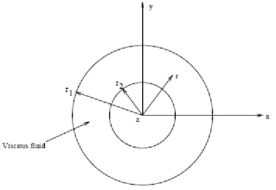
Hydrodynamic Forces of Viscous Fluid
Consider two concentric circular cylinders with an incompressible viscous fluid contained in the annulus as shown Yongming Cheng*, J. Kim Vandiver**
Proceedings of the ASME 2010 29th International Conference on Ocean, Offshore and Arctic Engineering OMAE2010 June 6-11, 2010, Shanghai, China
in Figure 1, where
r
1 andr
2are the interface radii between fluid and tubes. In real applications, the length of typical tubes and the wavelength of transverse vibration of the tubes are generally much larger than the radii ofr
i(
i
1
,
2
)
. Thus, thefluid field is assumed to be two-dimensional; that is, the axial motion of fluid is neglected. It is convenient to express the Navier-Stokes equation in the circular cylindrical coordinate system
(
r
,
,
z
)
. For small amplitude oscillations, the equations of motion can be linearized. Chen [2] found that fluid forces acting on cylinders are linear functions of the cylinder motions, and that the forces can be separated into two components. One is proportional to the real part of a coefficient defines as
il,Re(
il)
, which is in phase with the cylinder acceleration and is related to the added mass effect. The other is proportional to the imaginary part of
il, Im(il), which opposes the movement of the cylinder and is related to a damping mechanism. The hydrodynamic forces can thus be expressed in terms of cylinder acceleration and velocity as:
2 1 2 1 l l l il l il im
x
c
x
X
(1) Wherex
l(t
)
is the instantaneous displacement of thel
th cylinder (1 for outer cylinder and 2 for inner cylinder), the dot denotes differentiation with respect to time, andm
il andc
il are the added mass and fluid damping coefficients of the system, respectively, which can be written in terms of Chen‟s coefficients as:)
Im(
),
Re(
il l i il il l i ilr
r
c
r
r
m
(2)It is convenient to define an oscillation Reynolds number 2/
2
r
NR , where is the kinematic viscosity, and radius ratio
r
2/ r
1. The fluid force coefficient
il depends on the oscillation Reynolds numberR
N and radius ratio
in a very complicated way. Approximate solutions can be obtained in special cases [2].Formulation of a Coupled Riser System
Figure 2 illustrates a coupled riser system. The governing equations of motion for the external and internal risers can be written as: ) , ( ) , ( ) ( ] ) ( [ ] ) ( [ ), , ( ) , ( ) ( ] ) ( [ ] ) ( [ 2 2 2 2 2 2 2 2 2 2 2 2 2 2 1 1 2 1 2 1 1 1 2 1 2 1 2 2 t x f t x h t w x m x w x T x x w x EI x t x f t x h t w x m x w x T x x w x EI x (3)
where the subscripts „1‟ and '2' denote external and internal risers respectively; wi(i1,2)is the lateral displacement of a cylinder; E is modulus of elasticity; I (i1,2)
i is the moment
of inertia of the cross section; Ti(x),(i1,2) is the effective tension of a cylinder; mi(x),(i1,2) is the mass per unit length of a cylinder including the added mass of external fluid; h(x,t)(i1,2)
i is the hydrodynamic force defined in Eq. (1), and f (x,t)(i1,2)
i includes an external exciting force fie( tx, ) and a concentrated force from centralizers
) , ( tx fic , i.e.,
)
,
(
)
,
(
)
,
(
x
t
f
x
t
f
x
t
f
i
ie
ic .The concentrated force caused by centralizers, modeled as spring-dampers, can be written as:
( ) ( )
( ) ) , ( ), ( ) ( ) ( ) , ( 1 1 2 1 2 2 1 2 1 2 1 1 n Nm n n n c n Nm n n n c x x w w c w w k t x f x x w w c w w k t x f
(4)Where Nmis the number of centralizers, and
k
nandc
nare stiffness and damping coefficients for then
th centralizer. It is noted thatf
1(
x
,
t
)
f
2(
x
,
t
)
c
c
. Assuming that all centralizers have the same stiffness and damping coefficients, we define the dimensionless stiffness
k
* and dampingc
* as follows: 0 0 3 * 48 / E I l k k n ; * 0 0 2 / m l
c c n ,where the subscript „0‟ denotes the standard reference values for the pipe and
l
is the distance between centralizers. Substituting Eqs. (1), (2) and (4) into Eq. (3) yields:) , ( ) ( ] ) ( [ ] ) ( [ ), , ( ) ( ] ) ( [ ] ) ( [ 2 2 22 1 21 2 1 2 21 2 2 2 22 2 2 2 2 2 2 2 2 2 1 2 12 1 11 2 2 2 12 2 1 2 11 1 1 1 2 1 2 1 2 2 t x f t w c t w c t w m t w m m x w x T x x w x EI x t x f t w c t w c t w m t w m m x w x T x x w x EI x (5)
The following non-dimensioned parameters are defined as:
0 0 4 0 0 0 0 , , , / D w Y t l m I E l x s i i
,Where the subscript '0' represents the values at a reference cross section, and
0
D is a reference diameter for the pipe.
Eq. (5) is thus written into a non-dimensional form:
) , ( ) ( ] ) ( [ ] ) ( [ ), , ( ) ( ) ( ] ) ( [ ] ) ( [ 2 2 22 1 21 2 1 2 21 2 2 2 22 2 2 2 2 2 2 2 2 1 2 12 1 11 2 2 2 12 2 1 2 11 1 1 2 1 2 1 2 2 s f Y C Y C Y M Y s M s Y s Q s s Y s P s s f Y C Y C Y s M Y s M s Y s Q s s Y s P s (6) Assuming Y (s, )R (s)ei ,(k1,2) k k
and substituting it into Eq. (6) results in:) ( ) ( ] ) ( [ ] ) ( [ ), ( ) ( ) ( ] ) ( [ ] ) ( [ 2 2 22 1 21 1 2 21 2 2 22 2 2 2 2 2 2 2 2 1 2 12 1 11 2 2 12 1 2 11 1 1 2 1 2 1 2 2 s F R C i R C i R M R s M s R s Q s s R s P s s F R C i R C i R s M R s M s R s Q s s R s P s (7) In which
i
i e s f s F e s f s F1( ) 1( , ) , 2( ) 2( , ) , and is a dimensionless frequency, /0.The dynamic stiffness formulation of a coupled fluid/riser system is obtained by establishing a weak form of the equation in (7) using the Galerkin procedure. Each equation in (7) is weighted with virtual displacements,
v
1 andv
2, respectively: ds s F v ds R C i R C i R M R s M s R s Q s s R s P s v ds s F v ds R C i R C i R s M R s M s R s Q s s R s P s v s s s s ) ( } ) ( ] ) ( [ ] ) ( [ { , ) ( } ) ( ) ( ] ) ( [ ] ) ( [ { 2 2 2 22 1 21 1 2 21 2 2 22 2 2 2 2 2 2 2 2 2 1 1 2 12 1 11 2 2 12 1 2 11 1 1 2 1 2 1 2 2 1
(8)Integrating over the domain of interest
s
and transforming to lower the order of the derivatives in Eq. (8) and incorporate the boundary conditions as forcing terms gives the variational equations to be discretized by finite element interpolations. It is assumed that: 2 ) ( 2 ) ( 2 1 ) ( 1 ) ( 1 ˆ ) ( , ˆ ) ( U s H R U s H R m m m m (9) where the ( )( ) 1 s Hm and ( )( ) 2 sHm are the m-th elemental interpolation functions for the external and internal pipes, respectively. The WKB-based frequency-dependent shape functions are used in this research [2, 3].
1
ˆ
U and Uˆ2 are nodal
point displacements of the total element assemblage for the external and internal pipes. Likewise, the expressions for virtual displacements,
v
1 andv
2, are:2 ) ( 2 ) ( 2 1 ) ( 1 ) ( 1 ˆ ) ( , ˆ ) ( U s H v U s H v m m m m (10)
The formulation of the spectrum element method for the fluid/riser coupled system is thus developed by substituting Eqs. (9) and (10) into Eq. (8). The coupled equation can be written as: 2 1 2 1 22 21 12 11 ˆ ˆ ) ( ) ( ) ( ) ( F F U U K K K K (11)
The riser frequency response can be solved by using the algorithms based on Gauss elimination [5]. The skyline reduction method is used in the computer implementation of the Gauss elimination.
It is noted that the global stiffness K() in Eq. (11) is a
transcendental function of dimensionless frequency, 0
/
. For a uniform beam member, Wittrick and Williams (W-W) [6] presented an automatic computation of natural frequencies. For a tapered beam whose section properties vary regularly, Banerjee and Williams [7] gave a procedure to calculate natural frequencies.
However, a typical marine riser has non-uniform properties including mass distribution, bending rigidity, and tension. The procedures in [6, 7] can‟t be directly used for the application in this paper. The W-W algorithm is extended to a general non-uniform riser system for solving natural frequencies [3]. Once a natural frequency is obtained, the corresponding mode shape can be found by using the Gauss elimination method.
A computational program has been developed to solve for the natural frequencies and mode shapes, and the frequency response for a generally coupled riser system.
RESULTS
A coupled riser system is used for demonstrating the applications. Both the external and internal casings are simply supported and their specifications are as follows:
Outer diameter of external pipe =13.375 inches; Wall thickness of external pipe =0.380 inches; Added mass coefficient for external pipe=1.0;
Outer diameter of internal pipe =9.75 inches; Wall thickness of internal pipe =0.2975 inches; Young's modulus
E
=30000 ksi;Length of both cylinders
L
=1944 ft;Minimum tension on external pipe 4 102.510
T lbs;
Tension varying factor of external pipe = 47.00 lbf/ft; Minimum tension on internal pipe 4
201.010
T lbs;
Tension varying factor of internal pipe =30.63 lbf/ft; Number of evenly distributed identical centralizers=19, The distance between centralizers
l
= 97.2 ft.Natural Frequencies and Modal Shapes
Case 1- only coupled by springs
Each riser is discretized into 20 evenly distributed elements. The spring stiffness *
k of a centralizer is modeled with three values, 0.02, 0.2 and 2.0. Table 1 lists the first 10 natural frequencies (Hz) for each value of centralizer stiffness. This does not include the affect of fluid in the annulus, but does include the external added mass of water for the outer pipe. It shows that natural frequencies generally increase with rigidity of centralizers.
Table 1 Natural frequencies (Hz) of the riser system coupled by springs only
Order k*=0.02 k*=0.2 k*=2.0 1 0.0344 0.0344 0.0344 2 0.0692 0.0693 0.0693 3 0.0778 0.1049 0.1049 4 0.0982 0.1416 0.1416 5 0.1050 0.1795 0.1796 6 0.1259 0.2188 0.2190 7 0.1417 0.2217 0.2603 8 0.1576 0.2297 0.3031 9 0.1796 0.2429 0.3479 10 0.1923 0.2593 0.3945
Case 2- only coupled by ideal fluid
Natural frequencies of an ideal fluid coupled system are obtained by using the same algorithm. Each riser is regarded as one element. The first 10 natural frequencies are listed in Table
2. As expected, they are much lower than in Case 1. This also includes the added mass of the external fluid.
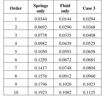
Case 3: generally coupled by springs and ideal fluid
This case is the combination of Case 1 (
k
*=0.02) and Case 2. Natural frequencies are found using 20 elements, as in Case 1. Table 2 lists the results and includes those in Cases 1 and 2 for comparison. This table demonstrates that the fluid lowers the natural frequencies.Table 2 Natural frequencies (Hz) of a coupled riser system Order Springs only Fluid only Case 3 1 0.0344 0.0144 0.0294 2 0.0692 0.0290 0.0368 3 0.0778 0.0335 0.0408 4 0.0982 0.0439 0.0525 5 0.1050 0.0591 0.0658 6 0.1259 0.0672 0.0681 7 0.1417 0.0748 0.0804 8 0.1576 0.0912 0.0960 9 0.1796 0.1020 0.1023 10 0.1923 0.1082 0.1125
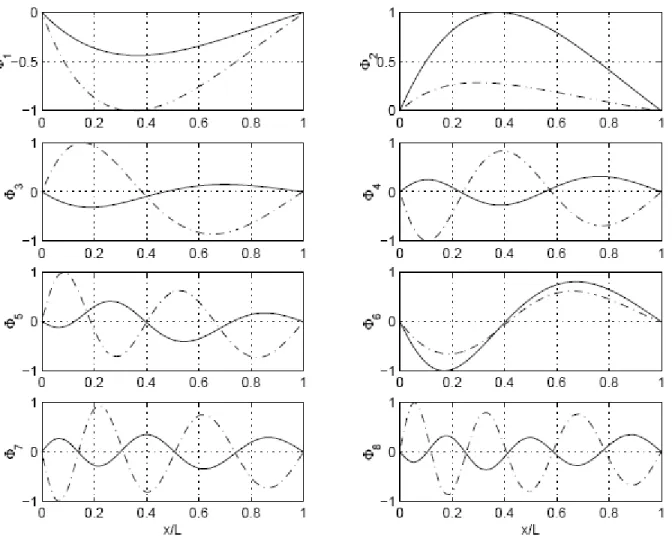
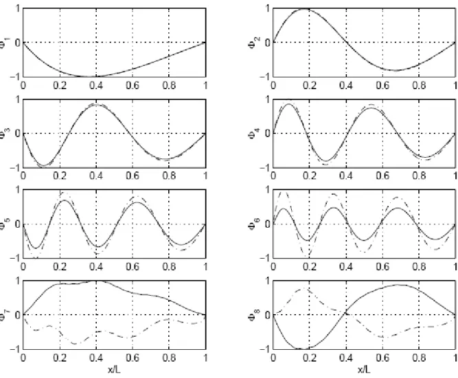
Figure 3 illustrates the first 8 mode shapes ,(i1,8) i
of the coupled riser system for Case 3. It indicates that when the system is weakly coupled by centralizers, its mode shapes are either in-phase or out-of-phase. The difference in the first two modes,
1 and
2
, is that the deformation of the internal riser is larger in mode one,
1
, while that of the external riser is larger in mode 2, 2.
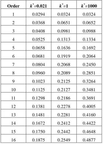
To find the impact of a centralizer stiffness on natural frequencies and mode shapes of the coupled riser system, we further set the stiffness ratio
k
* to be 1 and 1000. Table 3 shows the first 16 natural frequencies and includes the results corresponding tok
*=0.02 for comparison. This table demonstrates that the natural frequencies of the coupled system increase with the stiffness of centralizers. The first 4 frequencies fork
*=1 are very close to those fork
*=1000 for Case 3.Figure 4 depicts the first 8 mode shapes of the coupled system when
k
*=1. It indicates that when the system is moderately coupled by centralizers, the first few modes are in-phase while higher mode shapes are roughly either in-phase or out-of-phase but with shifted peaks. The higher the centralizer stiffness is, the higher the mode number one must investigate in order to achieve much relative motions between the pipes.The figure also shows that the system in the first two mode shapes vibrates as a single beam and no relative motion appears between the pipes.
Table 3 Natural frequencies (Hz) of a coupled riser system (Case 3) Order k*=0.021 k*=1 k*=1000 1 0.0294 0.0324 0.0324 2 0.0368 0.0651 0.0652 3 0.0408 0.0981 0.0988 4 0.0525 0.1313 0.1334 5 0.0658 0.1636 0.1692 6 0.0681 0.1919 0.2064 7 0.0804 0.2068 0.2450 8 0.0960 0.2089 0.2851 9 0.1023 0.2125 0.3264 10 0.1125 0.2127 0.3481 11 0.1298 0.2186 0.3691 12 0.1381 0.2278 0.4005 13 0.1481 0.2281 0.4160 14 0.1672 0.2412 0.4422 15 0.1750 0.2442 0.4648 16 0.1875 0.2549 0.4877 Response Spectrum
The impact of the couplings on the riser frequency response is further investigated for the centralizer stiffness of
k
*=1. The fluid viscosity is taken into account. The kinematic viscosity is assumed to be 410 0 .
1 m2/s, which is more viscous than water. A structural damping of 0.3% is also assumed in the computation.
Figure 5 illustrates that the top 10% of the external riser is subject to VIV excitation, which is caused by a uniform current
profile. The harmonic force is assumed to be uniformly distributed along the top 10% of the external pipe. This range is simulated as a power-in region. A sign function is used to determine the sign of the exciting force, based on the wave number of the external riser under average tension within the power-in region. With the harmonic exciting force, one can obtain the riser response spectrum by solving Eq. (11).
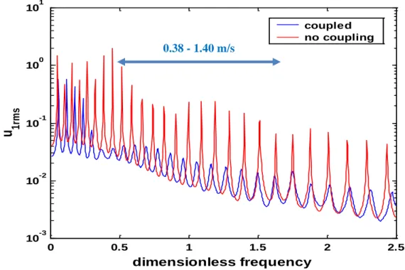
The problematic current speed range is from 0.38 to 1.40 m/s. The corresponding vortex shedding frequency is expected to be in the range from 0.25 to 1.00 Hz. The reference frequency is 0.56 Hz, which is the fundamental natural frequency for a simply supported internal pipe with the length of spacing between centralizers.
The Root-Mean-Square (RMS) value of the displacement of each riser is used to measure the global vibration level, which is defined as follows:
N j ij irms u u 1 2 , (i1,2).Figure 6 shows the frequency response variation for the external riser‟s RMS value. The corresponding VIV frequency range is marked in the figure. The figure indicates that the vibration level of the external riser is reduced significantly in the frequency range of interest because of the coupling from fluid and centralizers.
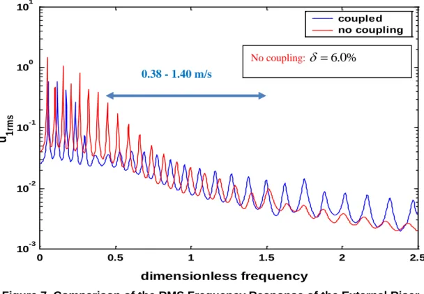
One can obtain a qualitative estimate of the equivalent structural damping due to the coupling by comparing to the response spectra between coupled and uncoupled cases. A trial and error method was used iteratively to find the same reduction within the range of frequency of interest by assuming a structural damping for an uncoupled pipe. As shown in Figure 7, the reduction of the external riser‟s vibration in the coupled case is compared to that in uncoupled case with 6.0% structural damping. The RMS stress is reduced approximately by a factor of 10. Thus the VIV fatigue damage is expected to be reduced by 1,000 to 10,000 times for this example.
CONCLUSIONS
This paper investigates the dynamic analysis of a general riser system coupled through fluid in the annuli between external and internal cylinders or through intermediate guides (centralizers) or through both. The conclusions that can be drawn from the work in this paper are:
(1) The theoretical formulation for a general fluid/ riser coupled system is constructed by using a spectrum element method and WKB-based frequency-dependent shape functions. The theoretical derivation is carried out for dual pipes. It can be further extended to include additional pipes, such as tubing in a TTR application.
(2) The coupling from fluid and centralizers affects natural frequencies and mode shapes of the riser system. Depending on
the number of centralizers and their stiffness, the mode shapes can be either in-phase or out-of-phase, or appear as a single beam without relative deformation.
(3) The impact of the coupling from fluid and centralizers on frequency response of the riser system can be significant. Fluid viscosity provides the damping to the coupled system. The spacing and stiffness of centralizers play an important role in the riser natural frequencies, modal shapes and frequency response. The fluid/riser coupling can be designed to suppress the vibration of an external casing caused by VIV. The internal pipe can be used as a vibration absorber to the external pipe. ACKNOWLEDGEMENT
This paper represents part of the research work when the first author studied at MIT for his Ph.D. with the second author as his supervisor. Thanks to SHEAR7 JIP members who supported the work.
Thanks Dr. Paul Stanton from Technip for his valuable comments.
REFERENCES
1. R. D. Blevins, “Flow-Induced Vibration,” 2nd Edition, Krieger Publishing Company, 2001
2. S. S. Chen, “Free Vibration of a Coupled Fluid/Structural System,” Journal of Sound and Vibration, 21 (4), 387-398, 1972
3. Y. Cheng, “Dynamic Stiffness and Transfer Matrix Analysis of Marine Riser Vibration (Ph.D. thesis),” MIT, Cambridge, 2001
4. Y. Cheng, J. Kim Vandiver, and G. Moe, “The Linear Vibration Analysis of Marine Risers Using the WKB-Based Dynamic Stiffness Method,” 251(4), 750-760, Journal of
Sound and Vibration, 2002
5. K. J. Bathe, “Finite Element Procedures,” Prentice-Hall, Inc., 1996
6. W. H. Wittrick and F. W. Williams, “A General Algorithm for Computing Natural Frequencies of Elastic Structures,” Vol. xx iv, pt.3, 264-284, Quart. Journ. Mech. and Applied
Math., 1971
7. J. R. Banerjee and F. W. Williams, “Exact Bernoulle-Euler Dynamic Stiffness Matrix for a range of Tapered Beams,” Vol. 21, pp. 2289-2302, Internation Journal for Numerical Methods in Engineering, 1985
8. G. Moe, Y. Cheng, and J. Kim Vandiver, “Riser Analysisby Means of Some Finite Element Approaches,” Proceedings of ETCE/OMAE,2002
Figure 1 Schematic of Two Concentric Pipes Containing Viscous Fluid
Figure 3 First 8 Mode Shapes of the Coupled Riser System
Figure 5 Model of an External Riser
0 0.5 1 1.5 2 2.5 10-3 10-2 10-1 100 101u
1r m sdimensionless frequency
coupled no couplingFigure 6 The RMS Frequency Response of the External Riser
0 0.5 1 1.5 2 2.5 10-3 10-2 10-1 100 101
dimensionless frequency
u
1rm s coupled no couplingFigure 7 Comparison of the RMS Frequency Response of the External Riser
No coupling:
![Figure 2 illustrates a coupled riser system. The governing equations of motion for the external and internal risers can be written as: ),(),()(])([])([),,(),()(])([])([ 2 2 222222222222 12112112112212 txftx t hxwxmxwxTxxwxEI txftxthxwxm](https://thumb-eu.123doks.com/thumbv2/123doknet/14753870.581495/3.918.485.848.783.944/figure-illustrates-governing-equations-external-internal-hxwxmxwxtxxwxei-txftxthxwxm.webp)