HAL Id: hal-03134897
https://hal.archives-ouvertes.fr/hal-03134897
Submitted on 1 Jun 2021HAL is a multi-disciplinary open access archive for the deposit and dissemination of sci-entific research documents, whether they are pub-lished or not. The documents may come from teaching and research institutions in France or abroad, or from public or private research centers.
L’archive ouverte pluridisciplinaire HAL, est destinée au dépôt et à la diffusion de documents scientifiques de niveau recherche, publiés ou non, émanant des établissements d’enseignement et de recherche français ou étrangers, des laboratoires publics ou privés.
Distributed under a Creative Commons Attribution| 4.0 International License
Titanate piezoelectric elements
Jy. Ferrandis, O. Gatsa, P. Combette, D. Fourmentel, C. Destouches, V.
Radulovic, L. Snoj
To cite this version:
Jy. Ferrandis, O. Gatsa, P. Combette, D. Fourmentel, C. Destouches, et al.. Acoustic instrumen-tation of the new generation of MTR: effect of nuclear radiation on modified Bismuth Titanate piezoelectric elements. EPJ Web of Conferences, EDP Sciences, 2020, 225, pp.04012. �10.1051/epj-conf/202022504012�. �hal-03134897�
1. IES- CNRS - Montpellier University, France
2. CEA Cadarache, France
3. Jozef Stefan Institute, Slovenia
Abstract :
In this article we present a first part of the results obtained during an irradiation campaign conducted at the Jozef Stefan Institute to observe the behaviour of piezoelectric materials under gamma and neutron flux. Specific instrumentation has been developed and has enabled the monitoring throughout the irradiation of several materials such as lead zirconate titanate (PZT) or modified Bismuth Titanate (BiT) in either massive or thick film form. Various parameters such as resonance frequency, electromechanical coupling coefficient, electrical capacitance, dielectric losses were measured as a function of the flow and dose received. The results obtained confirm that the samples work up to doses of 1018 n°/cm2 and that the behaviour of the samples varies according to their composition and form.
Keywords : Harsh environment, ultrasonic sensors, Material Test Reactor, piezoelectric materials, radiation effects
I.
Introduction
Nuclear fuel rods lifetime optimization helps in increasing combustion rate of nuclear fuel, hence reducing the volume of waste to be recycled. It can be achieved via in-pile control of the fuel rods interior environment. The measurements of the gas mixture (Helium and fission gases) in REMORA-3 experiment [1, 2] prove the possibility of measurements in plenum (upper part of combustive rod, whose role is to collect the fission gases) during operational conditions at up to 200 °C. A representation of REMORA device is given in Fig. 1.
(c)
Fig. 1 : REMORA acoustic gas sensor. (a) Schematic representation [1]. (b) Sensor overview [2]. (c) Experimental results including data processing [2].
The determination of the gas composition is based on the measurement of the sound velocity in a cavity filled with the gas to be analyzed. The emission and detection of the acoustic wave is achieved by coupling an acoustic element and a stainless steel plate that also serves as a confinement barrier [1]. In practice, the difficulties in brazing and ensuring of parallelism within the active element (Pz27 Ferroperm), stainless steel plate and reflector (Fig. 1) caused difficulties in signal measurement. Transducer’s limitation in operation temperature renders it impossible for application in a new type material testing reactor (MTR). Since 2011, our researches concern instrumentation for the future RJH reactor (to be used for testing devices for GEN IV reactors) and new requirements appeared such as : working temperature up to nearly 400°C, high level of nuclear radiations or minimally invasive measurement devices. Based on this limitation and the need to operate at higher temperatures, a second approach (which reduces the influence of the parallelism problem) is to use a screen-printing process in order to deposit piezoelectric material as the active element on a dedicated substrate. In previous work we developed a specific sensor based on screen printed lead zirconate titanate (PZT) and we proved the possibility of active element fabrication using material characterization [3] and ultrasonic measurements [4].
Our previous works demonstrated that the technology based on screen-printed piezoelectric layers was viable in a non-radiative environment and that the technology using solid materials was also viable for a radiative environment but for temperatures below 140°C. In order to observe the influence of a radiative environment on the performance of piezoelectric materials of different kinds, we have set up an experimental campaign at the Jozef Stephan Institute (JSI) with two objectives. On the one hand, to observe and compare the behavior of two families of piezoelectric materials: Lead Zirconate Titanate (PZT) and modified Bismuth Titanate (BiT). For the first type, the samples are of type PZ27 (Meggit-Ferroperm) and for the second type they are of type PZ46 (Meggit-Ferroperm). On the other hand, ensure that sensor based on screen-printed process can be used in a radiation environment. For the latter, the piezoelectric screen printing layers will be made from PZ27 type materials as mentioned in [3].
II. Materials and Methods
A.
Specimens
Two different types of piezoelectric materials were analyzed. Firstly, bulk materials as PZ27 and PZ46 were purchased from Ferroperm (Meggit) in the form of 10 mm in diameter, 600 um thick, acting as a thickness mode resonator. Secondly, thick films of PZ27 were deposited by screen printing process on alumina substrate. PZT ink has been made by mixing of 74% in weight of PZT powder (PZ27 from
Fig. 2 : Piezoelectric thick film
In this work, for PZT ceramics elaboration, conventional sintering method was used. During this step, specimen were placed inside a Carbolite RWF1100 furnace and sintered under lead oxide-saturated atmosphere at 850 °C. The limitation of sintering temperature by 850 °C was due to the effect of the electrode deposition in sensor production.
Fig. 3 : Standard sintering protocol used for fabrication of PZT
The sintering protocol used for ceramic fabrication is shown in Fig. 3 with the dwell period at 850 °C of 15 minutes. The time of sintering was adapted according to the protocol of Ag/Pd9693-G conductive ink and was successfully used for PZT components in previous studies.
B.
Experimental set-up
1.
JSI TRIGA reactor irradiation facilities
JSI TRIGA Mark II reactor is a typical TRIGA type reactor that is to say a pool type reactor, cooled by natural convection, with maximal steady thermal power of 250 kW. The reactor core has an annular configuration with a diameter of 44.2 cm, with 91 in-core positions for fuel elements, 4 control rods, and numerous irradiation positions (Fig. 4).
Fig. 4 : JSI TRIGA Mark II reactor core with typical fuel element configuration and irradiation positions.
Nuclear fuel is a homogeneous mixture of fuel and moderator in form of uranium zirconium hydride (U-ZrH). Fuel meat, with central zirconium rod and graphite reflector on either side, encased in stainless steel cylindrical enclosure (radius 1.89 cm and length of 72.5 cm) with bottom and top pin comprise a fuel element. Fuel elements are held in place by top and bottom aluminium grid, each consisting of a plate with holes for fuel elements. Reactor usually operates with central position (A1 or CC), and most of the F-ring positions empty and available for irradiations and two control rods (Transient and Safety) completely withdrawn.It is equipped with numerous irradiation positions, where samples can be irradiated by neutrons and γ-rays. Irradiation position selection is based on its properties, such as physical size and accessibility, as well as neutron and γ-ray spectra, flux and dose intensities.
2.
Instrumental Bench
In order to monitoring the electrical behavior of different piezoelectric materials and devices, impedance analyzer (Keysight 4990A) associated with a multiplexer (Agilent 34902) were used. Instruments were connected by specific coaxial cables of 10 m length, purchased from thermocoax (silica core and 50 ohm matching), to a specific specimen holder built in aluminum which contained the different specimens to be analyzed (Fig. 5). Altogether, 10 channels were used allowing for the studies of 6 piezoelectric elements, 3 for impedance calibration and 1 channel for the temperature measurement with type K thermocouple.
(a) (b) (c)
Fig. 5 : pictures detailing the different piezoelectric elements inserted in the specimen holder. (a) piezoelectric thick films on alumina substrate, (b) all piezoelectric samples and associated cables before closing the cavity, (c) sealed cavity
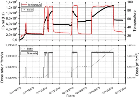
During 5 days, the samples were placed in air into the triangular irradiation channel where calculated neutron flux at full power (250kW) and total dose during experiment are described on Fig. 6 (uncertainty is about 5%).
loss obtained at different frequencies and different temperatures (measurement channel, water, …), were acquired through a specific software during experiment.
3.
Data processing
Following a theoretical approach, based on the KLM model [17], the electro-mechanical parameters of piezoelectric elements were calculated by matching experimental measurement with theoretical values. Three complex parameters, parallel frequency (Fp∗), electro-mechanical coupling factor (kt∗), capacitance (C∗) were adjusted using software in order to fit measured data. Theoretical impedance was determined by equation 1 for the bulk elements and by equation 2 for thick films :
Zelec= �−C∗iω� �1−(4Fp∗kt∗2tan� ω 4Fp∗�� ω (1), Zin= Zc Zout+ jZctan (φ) Zc+ jZouttan (φ) (2) whereby Fp∗, kt∗, C∗ are complex values of Fp, kt, capa; and ω is the angular frequency.
Complex values of these parameters can be found from the standard equations of piezoelectricity [18]:
Fp
∗= Fp �1 +
i
QFp
� (3) , kt
∗= kt�1 − i/qkt
2(4) ,
C
∗= capa �1 −
i
qcapa
� (5)
whereby QFp – mechanical quality factor, qkt – electro-mechanical loss and qcapa associated to dielectric loss. The parameters are then deduced from the experimental curves fitted with previously described model as shown in Fig. 7.
Fig. 7 : real and imaginary parts of electrical impedance : left PZ27, right screen-printed PZ27
Table 1 shows an example of results obtained, but with difficulties in obtaining the Qcapa parameter for PZ46. In view of this, we have chosen not to monitor the evolution of complex parameters and to focus only on the Fp, kt and capa parameters.
TABLE1
Electro-mechanical parameters of PZ27 and PZ46 samples fitted with model.
Symbol Quantity Value PZ27 Value PZ27 thick film Fp parallel frequency 4.262 MHz 13.798 MHz QFp mechanical quality factor 121 17,57 kt electro-mechanical coupling factor 0.46 0.31 Qkt electro-mechanical loss 35.13 NA capa capacitance 1.11 nF , (ε33= 958) 1.23 nF, (ε33= 470)
qcapa dielectric loss 154 NA
These three parameters generally represent the different properties of piezoelectric materials and their monitoring provides important information on their different behaviours : mechanical for FP, electrical for CP and electromechanical coupling for Kt.
III. Results
We can observe on Fig. 8 an experimental curve showing the relative variation of the resonance frequency of a PZ27 element as a function of the reactor operating parameters, in particular with the dose rate and the total dose. The temperature curve corresponds to that recorded in the sample holder inserted in the irradiation channel.
Fig. 8 : example of experimental results obtained during 5 days
We noticed that during the transient phases, particularly during the reactor's ramp-up or during the decrease in its power, some difficulties in adjusting the curves on the theoretical model. We assumed that these observations could be due either to dose rate effects (inducing generations of electrical charges by pyroelectric effect), or to alterations of resonance peaks, or to resonance mode couplings that the 1-dimensional model was not able to take into account. The results presented below correspond only to steady states obtained after returning the irradiation channel to room temperature. We will therefore exclusively consider the influence of the effect of the neutron dose on the measured parameters.
(a)
(b)
Fig. 9 : comparison between PT27 and PZ46. (a) relative variation of resonance frequency, (b) relative variation of electromechanical coupling.
Curves shown in Fig. 9 correspond respectively to the relative variation of the resonance frequency Fig. (a) and to the electromechanical coupling coefficient Fig. (b) for 4 piezoelectric disks based on 2 Lead Zironate Titanate and 2 modified Bismuth Titanate. Concerning the variation of the resonance frequency, we observe a significant difference in behaviour between the two types of samples revealing a better performance for PZ46 but this variation does not exceed a maximum of 2% for the PZ27 sample for a dose up to 1018 n°/cm2. As already mentioned by Holber [5] and Sinclair [6] variation of resonance frequency could be induced by modifications of stress constant of piezoelectric materials due to ionization effect. Concerning the evolution of the electromechanical coupling coefficient, the works of Broomfield [7] and on piezoelectric materials reveal a decrease in remnant polarization associated with neutron dose and thus a decrease in electro-mechanical coupling. This effect can be associated with the presence of oxygen deficiencies that actually contribute to an increase in the intrinsic electrical conductivity of the material and a decrease in the electrical-mechanical conversion efficiency. We also noted, specifically for PZ46 samples, a heterogeneity in the results relating to the coupling coefficient. Although these results are not presented in this document, this is also the case when measuring the capacitance of samples of the same material. Although we have taken care to ensure that similar samples are taken before irradiation, with more difficulties for PZ46 materials, their behaviour under irradiation seems more homogeneous for PZ27 samples than for PZ46.
(a)
(b)
Figure 10 : comparison between PZ27 bulk and thick film. (a) relative variation of resonance frequency, (b) relative variation of electromechanical coupling.
Through the results presented in Figure 10, it can be observed that the behaviour of the massive zirconate titanate lead and its declination in thick layers evolves in the same way according to the dose received. The same assumptions as above can be made to explain the increase in the relative variation in resonance frequency, but not exceeding 4% for a dose up to 1018 n°/cm2. With regard to the electromechanical coupling coefficient, the difference between thick layers and solid materials is greater. Indeed, the relative variation of this coefficient is 6 times greater for PZ27 layers deposited on alumina and is up to 30%. We can also hypothesize that piezoelectric materials with lower thicknesses may have higher sensitivity to the irradiation dose, as ionization phenomena occurring at lower thicknesses would lead to faster degradation of the material's intrinsic properties and gamma self-heating may have been more important for thick layers deposited on an alumina substrate with a volume 40 times greater than massive piezoelectric elements and in contact with the sample carrier.
IV. Conclusion
An experimental bench has been developed taking into account the specificities associated with a Material Test Reactor in order to observe the radiative effects on specific parameters of piezoelectric materials. The experimental campaign carried out at JSI made it possible to achieve the two initial objectives:
We achieved the first objective of observing and comparing the performances of materials such as PZ27 and PZ46. The experimental results, in agreement with the state of the art, confirm the fact that modified bismuth titanate (PZ46) has better performances than lead zirconate titanate (PZ27) due to its higher Curie temperature and its behavior on radiative environment.
For the first time, thick layers of piezoelectric materials deposited on alumina substrates could be tested in a radiative environment. Based on results, we also confirmed that screen-printing technology could be used to produce miniaturized acoustic sensors for in situ research reactor instrumentation.
V. References
[1] E. Rosenkrantz, J.Y. Ferrandis, F. Augereau, T. Lambert, D. Fourmentel, X. Tiratay, “An Innovative Acoustic Sensor for In-Pile Fission Gas Composition Measurements,” IEEE Transactions on Nuclear Science, vol. 6, no. 2, pp. 1346-1353, 2013.
[2] D. Fourmentel, J.F. Villard, J.Y. Ferrandis, F. Augereau, E. Rosenkrantz, M. Dierckx, "Acoustic sensor for in-pile fuel rod fission gas release measurement," IEEE Transactions on Nuclear Science vol. 58, no. 1, pp. 151-155, 2011.
[3] F. Very, P. Combette, D. Coudouel, A. Giani, E. Rosenkrantz, J.Y. Ferrandis, D. Fourmentel, “Piezoelectric thick film sensors: Production and characterization,” Applications of Ferroelectric and Workshop on the
Piezoresponse Force Microscopy (ISAF/PFM), IEEE International Symposium, 2013, pp. 287-290.
[4] D. Lapeine, J.Y.Ferrandis, D. Laux, F. Pascal, P. Combette, “Development and integration of screen printed transducers for the detection of pollutants in aquatic environments,” Design, Test, Integration and
Packaging of MEMS/MOEMS (DTIP), IEEE, pp. 1-5, May 2016.
[5] K.E. Holbert, S. Sankaranarayanan, S.S. McCready, D.R. Spearing, A.S. Heger, “Response of piezoelectric acoustic emission sensors to gamma radiation”, Proceedings of the 7th European Conference on Radiation and Its Effects on Components and System, RADECS 2003, Noordwijk, Netherlands, September 2003.
[6] A.N. Sinclair, A.M. Chertov, “Radiation endurance of piezoelectric ultrasonic transducers – A review”, Ultrasonics, Volume 57, 2015, Pages 1-10,
[7] G.H. Broomfield, “The effects of temperature and irradiation on piezoelectric acoustic transducers and materials”, UKAEA Report AERE-R 11 942, Harwell, UK, 1985.
[8] K.E. Holbert, S. Sankaranarayanan, S.S. McCready, D.R. Spearing, Response of lead metaniobate acoustic emission sensors to gamma irradiation, IEEE Trans. Nucl. Sci. 52 (2005) 2583–2590.
![Fig. 1 : REMORA acoustic gas sensor. (a) Schematic representation [1]. (b) Sensor overview [2]](https://thumb-eu.123doks.com/thumbv2/123doknet/13596634.423487/3.937.349.588.133.375/fig-remora-acoustic-sensor-schematic-representation-sensor-overview.webp)