HAL Id: hal-02163064
https://hal.uca.fr/hal-02163064
Submitted on 23 Jun 2019
HAL is a multi-disciplinary open access
archive for the deposit and dissemination of
sci-entific research documents, whether they are
pub-lished or not. The documents may come from
teaching and research institutions in France or
abroad, or from public or private research centers.
L’archive ouverte pluridisciplinaire HAL, est
destinée au dépôt et à la diffusion de documents
scientifiques de niveau recherche, publiés ou non,
émanant des établissements d’enseignement et de
recherche français ou étrangers, des laboratoires
publics ou privés.
Trust-Based Variable Impedance Control for
Cooperative Physical Human-Robot Interaction
Harsh Maithani, Juan Antonio Corrales Ramon, Youcef Mezouar
To cite this version:
Harsh Maithani, Juan Antonio Corrales Ramon, Youcef Mezouar.
Trust-Based Variable
Impedance Control for Cooperative Physical Human-Robot Interaction.
2019 IEEE
Interna-tional Conference on Mechatronics (ICM 2019), Mar 2019, Ilmenau, Germany.
pp.706-711,
Trust-based Variable Impedance Control for
Cooperative Physical Human-Robot Interaction
Harsh Maithani
Universit´e Clermont Auvergne SIGMA Clermont, Institut Pascal F-63000 Clermont-Ferrand, France [email protected]
Juan Antonio Corrales-Ramon
Universit´e Clermont Auvergne SIGMA Clermont, Institut Pascal F-63000 Clermont-Ferrand, France [email protected]
Youcef Mezouar
Universit´e Clermont Auvergne SIGMA Clermont, Institut Pascal F-63000 Clermont-Ferrand, France [email protected]
Abstract—This paper proposes a novel trust-based impedance control scheme based on task performance metrics and faults that allow a robot to act as a supervisor for its human partner in a cooperative human-robot task. A dynamic Trust model is used to modulate the robot stiffness as a function of the user performance. The task metrics are accuracy, forces applied by the user and the time taken for completion of the task. Results show that the proposed control scheme results in lower forces applied by the user while simultaneously ensuring accuracy of the task. The proposed methodology can be expanded to train a novice user to match the performance of a professional user.
Index Terms—Trust,Variable Impedance Control,Physical Human-Robot Interaction
I. INTRODUCTION
Robots have been used in industrial settings since many decades, however due to safety purposes industrial robots have been traditionally kept isolated from human operators. As such collaboration between humans and robots has been limited. But now there is a growing emphasis on incorporating robots in more intimate environments alongside humans to make full use of both human and robot capabilities by working in teams. This has resulted in the development of new generation robots which are lightweight (e.g KUKA LWR), can be programmed on the fly etc. Some examples where physical human-robot interaction (pHRI) has been used recently are - collaborative object transportation [1], assistive welding [2], car windshield positioning [3] etc.
Impedance control and admittance control are popular con-trol techniques used for physical human-robot interaction tasks as they establish a dynamic relationship between the robot and the environment. Tuning of the impedance parameters in a pHRI task is crucial as they determine the performance as well as the intuitiveness felt by the user while performing the task.
Hogan [4] introduced the impedance control scheme for robotic manipulators. Impedance control and admittance con-trol are the preferred concon-trollers for physical human-robot in-teraction, the equations for both the impedance and admittance control are the same but the inputs/outputs are different. In the impedance control scheme the input is displacement/velocity and output is force whereas in the admittance control scheme the input is force and output is displacement/velocity.
Fig. 1. A cooperative human-robot trajectory tracking task. The user traces the trajectory in the x-y plane with a laser pointer attached to the end-effector of the robot using torque-based impedance control.
The robot impedance model can be written as a mass-spring-damper equation (See (2)). Controller stability in pHRI is one of the main reasons why impedance parameters are tuned. For accurate positioning or accurate tracking the user has to stiffen his arm muscles. In admittance control with time delay there is a likelihood of instability in human-robot cooperation if the user’s hand is coupled to the robot and he increases his hand stiffness. There always exists inertia and damping parameters that can cause instability. One easy way to resolve this is by increasing the robot stiffness or damping term but this results in extra load for the human during the task.
In literature there are many examples where the tuning of impedance parameters has been investigated. In [5] the robot controller impedance parameters MR, BR, KR for the
robot experiment were taken from a prior human-human experiment and were not computed and adapted in real time. Only the damping term BR was varied from
one pHRI experiment to another. During the experiment the MR, BR, KR parameters were constant. In [6] a switch type
variable admittance control was introduced in which the damping term BR changed depending on velocity, although
for a particular trial the BR was kept constant. Rahman et
al. [7] introduced a variable admittance control scheme in which BRand KRvaried depending on the cartesian velocity.
BR and KR changed dynamically according to a reference
graph from a prior human-human experiment. Tsumugiwa et al. [8] used variable damping control for a calligraphy task. Only the stiffness of the human arm KH was computed. The
damping coefficient of the robot controller varied according to human hand stiffness in low velocity range. Ikeura et al. [9] used variable admittance control with damping coefficient determined from the minimization of a heuristic cost function (stiffness was ignored). In [10] the stiffness coefficient of the robot controller KR varied according to the fatigue of
the user’s arm muscles during a cooperative pHRI task. The muscle fatigue was measured using EMG signals. In [11] the damping coefficient of the robot controller varied according to the time derivative of the force applied by the user. The author used the time derivative of the force applied as an indication of user’s intention to accelerate, decelerate or reverse the direction of movement and hence vary the damping term BR
accordingly.
In recent times there have been efforts to model factors that influence human behaviour with robots in the environment, especially when humans and robots have to work together in teams. Trust is a factor that affects a human’s performance when working in teams, whether with other humans or robots. In this paper we will develop a mathematical trust model that can be integrated into an impedance control scheme. A mathematical model of the trust of one agent on another was presented in [12] but this was a discrete model and not dynamically time-varying. Lee and Moray [13] proposed a dynamic computational trust model that is a function of performance and faults (See (4)). They used ARMAV (Au-toregressive Moving Average Vector form) to determine the coefficients. The model of the human and robot performance is at the discretion of the person conducting the experiment. This model suggests that fall in trust is immediate upon observing a malfunction but trust recovery is slow. Hancock et al. [14] established that among the human factors that affect the trust between humans and robots, performance has the highest impact.Walker et al. [15] used computational trust to utilize redundancy of the robot to give postures that corresponded with the level of trust of the robot on the human. Some researchers have treated the computational trust as a task metric that has to be optimized. Saeidi and Wang [16] used Model Predictive Control to optimize this task metric at each time step with the output of the optimization being the robot speed. In this work we will focus on robot-to-human trust and how a dynamically varying trust value can be used to adjust
the impedance parameters of the robot. The motivations of our work are two fold
-1) In settings such as factories, there is immense pressure on workers to satisfy multiple criteria simultaneously e.g in an assembly task, workers must maximize the productivity while minimizing quality defects. As such in our work we want to simulate a task wherein multiple task performance metrics are desired to be optimized. 2) As robots become more commonplace in work
environ-ments they will take flexible roles that vary from leaders to followers to team mates to supervisors. In our work we have focused on a task to demonstrate how a robot can act as a supervisor and evaluate the progress being made by the user. Such an approach can be considered as a preliminary step towards the creation of a training module to train new workers to the same performance levels of a professional. In our task the robot can reward or punish the human user depending on the performance but we can not call the robot a ‘teacher’ as it does not demonstrate to the user the ‘correct’ approach.
In this paper we will discuss how a human’s performance in a task (task performance metrics) can affect the value of robot-to-human trust and how robot-robot-to-human trust can be integrated in a variable impedance control scheme. Our contributions are-1) A new trust based variable impedance control scheme
for a cooperative human-robot task.
2) A scheme to demonstrate how a robot can supervise the performance of a human partner in a cooperative task and reward or punish the user depending on the performance.
3) Integrating multiple task metrics for impedance shaping of the robot impedance controller.
To the best of the author’s knowledge there is no prior work on this subject. Unlike other works of pHRI where the robot acts as a partner or an assistant to reduce the physical or cognitive load on a human user, in our work the robot acts as a supervisor of the human user’s performance. Also there are no known previous works on direct impedance shaping based on task metrics.
II. IMPEDANCECONTROL
The robot arm dynamics in the joint space are described as M (q)¨q + C(q, ˙q, ) ˙q + G(q) = τ + JTF (1) where M (q) ∈ <n×n is the symmetric bounded
positive-definite inertia matrix; C(q, ˙q, ) ˙q ∈ <n denotes the Coriolis
and Centrifugal force; G(q) ∈ <n is the gravitational force;
τ ∈ <n is the vector of control input; and F ∈ <n denotes
the forces exerted by the human limb (as this is a pHRI task) The impedance model of a robot can be written as
MRx + B¨ R( ˙x − ˙xd) + KR(x − xd) = F (2)
and the impedance model of the human arm rigidly in contact with a tool mounted on the end-effector of the robot can be written as
where MR is the desired robot inertia, BR is the desired
robot damping, KR is the desired robot stiffness, ¨x is the
current robot cartesian acceleration, ˙x is the current robot cartesian velocity, x is the current robot cartesian position,
˙
xd is the desired robot cartesian velocity, xd is the desired
robot cartesian position, F is the interaction force, MH is
the estimated human limb inertia, BH is the estimated human
limb damping, and KH is the estimated human limb stiffness.
As the tool mounted on the end effector is rigid so we can make the assumption that the forces applied by the user’s hand are transmitted to the robot completely. As such both equations (2) and (3) have the same F . In this paper we will not be estimating the human impedance parameters but instead will modulate the robot impedance parameters based on task performance metrics.
III. TRUSTMODEL
The equation of trust between two agents (human-to-robot or robot-to-human) can be for unilateral trust or mutual trust, but even when a mutual trust equation is considered the human-to-robot trust and the robot-to-human trust develop separately. It is the discretion of the designer to decide what to consider as performance and faults in the trust model. The equation of the trust model as given in [13] is
-T (k + 1) = α1T (k) + α2P (k + 1) + α3P (k) + α4X(k + 1)
+ α5X(k) (4)
where T (k) = trust in trial k and T ∈ [0, 1], P (k) = perfor-mance at the end of trial k and P (k) ∈ [0, 1], X(k)=faults at the end of trial k and X(k) ∈ [0, 1]. α1, α2, α3, α4, α5 are
coefficients to be decided. In our work only the robot-human trust is considered, so for us T (k) is the trust of the robot on the human and P (k) and X(k) are the performance and faults of the human user respectively.
In this work our objectives are
-1) To identify a cooperative human-robot task in which the human performs the task completely, the robot acts as a supervisor and can only change the settings of the task. 2) To identify a set of metrics to measure the performance of the user in the task. The nature of the task and the choice of metrics should be such that the metrics are in conflict with each other i.e in a general scenario it is not possible for the human user to maximize multiple metrics simultaneously. We have stated this earlier in our motivations that in settings such as factories it is not possible to satisfy multiple criteria simultaneously and we want to simulate such a task in our work. 3) To establish a relation of the trust of the robot on the
human as a function of the task performance metrics. 4) To establish a reward / punishment as a function of the
robot-human trust value.
In this work our task is a trajectory tracking task and the details will be explained in the next section. The task performance metrics are
-1. Time performance metric
The task completion time for trial k is denoted by t(k). Our performance metric for the task completion time is defined as
Ptime(k) =
t(k) − tmax
tmin− tmax
(5) Ptime(k) ∈ [0, 1] and tmin and tmax are the minimum and
maximum time taken to complete a trial by the user recorded in pre-experiment trials. If t(k) ≤ tmin or t(k) ≥ tmax
then the values are redefined i.e tmin=t(k) or tmax=t(k)
respectively.
2. Force performance metric
The average force applied by the user to complete the trajectory in trial k is F (k). F (k) is calculated as
F (k) = N P i=1 q F2 xi+ F 2 yi N (6)
where N is the number of points in which the trajectory is divided and Fxi and Fyi are the forces applied in the x and
y direction at the point i of the trajectory. Our performance metric for the average force applied by the user is defined as
Pf orce(k) =
F (k) − Fmax
Fmin− Fmax
(7) Pf orce(k) ∈ [0, 1] and Fmin and Fmax are the minimum
and maximum of the average forces applied by the user over multiple pre-experiment trials. If F (k) ≤ Fmin or
F (k) ≥ Fmax then the values are redefined i.e Fmin=F (k)
or Fmax=F (k) respectively.
3. Faults (metric for task accuracy)
Our task is in the x-y plane and our trajectory is divided into N number of equally spaced points (xi, yi) ∈ <2, i ∈ [1, N ].
Once a trial is over, we determine the closest points (xinearest, yinearest) to the ground truth using the k-nearest
neighbors algorithm (k-NN). The error between the ground truth and the measured point is defined as
di= p (xinearest− xi) 2+ (y inearest− yi) 2 (8)
and the total error for trial k is Perror(k) =
N
X
i=1
di (9)
If the error di at point i is above a certain threshold dth then
we count it as a foul ei where
ei=
(
1 if di≥ dth
0 if di< dth
(10) The total number of fouls for trial k is E(k) where E(k) is defined as E(k) = N X i=1 ei (11)
If E(k) exceeds a threshold Eth then we impose a penalty
Xpenalty, and our fault Xerror(k) is defined as
Xerror(k) =
(
Xpenalty if E(k) ≥ Eth
0 if E(k) < Eth
(12) We have now defined our performance metrics Pf orce and
Ptime as well as our faults Xerror. Using these metrics our
proposed trust model is
T (k + 1) = α1T (k) + α2Pf orce(k + 1) + α3Ptime(k + 1)
+ Xerror(k + 1) (13)
The Time performance metric (Ptime) is used to compare
how fast a user is performing the task with regards to a reference, in our experiments the reference is taken from pre-experiment trials with the same user, but it could also be the time taken by a professional for the same task. Lower the time taken for completion of the trial, higher the Ptime. Similar
to Ptime the Force performance metric (Pf orce) is used to
compare how much force the user is applying with regards to a reference. The Fault metric (Xerror) is used to measure
the error in the accuracy of the trajectory following task. If the number of fouls E(k) for a particular trial goes above a pre-defined threshold then the human user commits a fault and loses the robot’s trust and a penalty Xpenalty is imposed.
After defining the task metrics and the trust model we have to define the reward and punishment policy - the robot stiffness policy i.e the variation of robot stiffness as a function of the current trust value. This is explained in the next section.
IV. EXPERIMENTS
To fulfill our objectives we devised a task with the following details: (1) Our cooperative task is a trajectory tracking task. (2) The shape of the trajectory is a two-dimensional 30 cm x 20 cm rectangle. (3) A laser pointer coupled tool is attached to the end effector of a robot. There is a force-torque sensor between the tool and the end effector. The user moves this tool to track the trajectory. (4) One complete coverage of the trajectory is considered as one trial. (5) The controller is a torque-based impedance control. (6) The laser pointer helps the user track the trajectory but the position recorded is of the end effector of the robot. (7) To simulate a time-pressure environment, the user was given a time of 2 minutes with the instruction -“Complete as many trials with the least amount of error” (8) The primary goal of the robot is to ensure accuracy of the trajectory tracking task. The secondary goal is to assist the user in completing the task with the minimum force possible and the tertiary goal is to assist the user in completing the task in the minimum time possible. (9) It has been shown in literature that in cooperative tasks with a robot, high stiffness is directly related to high accuracy for positioning tasks. As such the robot’s reward/punishment for the user is to increase or decrease the robot stiffness depending on the performance of the user. We will explain the methodology to customize the robot stiffness policy for one user although the experiments were performed for 5 different users and gave similar results.
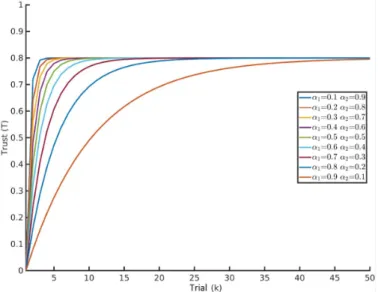
Fig. 2. Variation of Trust with parameter weights for a single task metric trust model. Performance is assumed to be constant i.e P = 0.8. The graph shows that even with constant performance the value of trust will increase with every trial and ultimately converge to the performance value.
Our experimental apparatus consisted of a KUKA LWR 4+ robot with 7 degrees of freedom, with a 6-axis ATI Gamma force-torque sensor mounted at the end-effector. The high level program was written in MATLAB and connected to the network via ROS. A laser pointer was attached rigidly to a cylindrical tool mounted below the force-torque sensor. The controller used was the in-built cartesian impedance controller with the following control law
-τcmd = JT(Kc(x−xd)+D(dc))+fdynamics(q, ˙q, ¨q) (14)
where q ∈ <n is the joint position vector, K
c is the
stiff-ness matrix in the end-effector frame,Dc is the normalized
damping parameter in the end-effector frame,x and xdare the
current and the desired pose of the end-effector respectively in the global frame. The translational stiffness Kx, Ky, Kz ∈
[0.01, 5000] N/m and rotational stiffness KAz, KBy, KCx ∈
[0.01, 300] N/m-rad
For our experiment we needed the laser pointer (i.e the tool) to be facing downwards vertically all the time, so we set the rotation matrix of the pose to be constant, the values of KAz, KBy, KCx were set to 300 N/m-rad. The value of
damping was set to Dc = 0.7 and xd= x.
We first had to determine the weights α1, α2, α3. Fig.2
shows an example of the variation of Trust with the parameter weights for single task metric model i.e only two parameters - α1 and α2. The performance is considered constant at
P = 0.8. A low value of α1 would give less weightage
to previous Trust value and more weightage to the current performance of the user. We wanted the value of Trust to increase rapidly so for all our experiments we chose α1= 0.1.
For the other two weights α2, α3 we used the equation
α1+ α2+ α3 = 1 and varied the weights α2, α3, which is
Fig. 3. Forces applied by the user for different robot stiffness
Fig. 4. Normalized performance Pf orces
we performed a pre-experiment trial with the user at different robot stiffness’ using constant impedance control (i.e without Trust based variable impedance control). The highest accuracy was with the highest robot stiffness i.e K = 5000 N/m and the highest number of fouls with K = 5000 N/m was less than 300 so we took this as the threshold for faults i.e Eth= 300. This
makes sense as we want the robot to reduce the stiffness only if the user can maintain the accuracy. From the pre-experiment trials we obtained the values of Tmin = 10 seconds,Tmax= 30
seconds, Fmin= 9 N, Fmax=20 N. These values were needed
to normalize the performance metrics between 0 and 1. Next
TABLE I
PARAMETERS FOR EXPERIMENTS
N 4000 dth 0.005
Eth 300 Xpenalty -0.4
Tmin 10 s Tmax 30 s
Fmin 9 N Fmax 20 N
we had to identify the difference in the force performance for different stiffness values. The results are shown in Fig. 3. Using (6) we normalized the Force Performance which is shown in Fig.4. Using these results we can identify bands of force performance for different robot stiffness in Table 2. The aim of the supervisor i.e the robot is to assist the user in achieving the task with lower forces and minimum time as long as accuracy is being maintained (i.e faults are not committed).
TABLE II
FORCE PERFORMANCE BANDS Kx= Ky(N/m) Pf orce 5000,4000,3000 0 ≤ Pf orce≤ 0.35 2000 0.35 < Pf orce≤ 0.55 1000 0.55 < Pf orce≤ 0.65 500 0.65 < Pf orce≤ 0.8 100,1 0.8 < Pf orce≤ 1
From Fig. 2 we can see that for constant performance the value of trust converges to the numerical value of the performance. We know from Fig. 4 that for a particular robot stiffness value the force performance lies in a band and hence from these two statements we know that the value of trust will get stuck inside a particular interval if the robot stiffness does not change (and consequently if the force performance does not change). As such for our robot stiffness policy we can not use the force performance bands directly as this will result in the robot stiffness staying the same value throughout. If the supervisor has to assist the user then upon a certain value of trust being reached, the robot stiffness should fall to the next band allowing the user the opportunity to perform the next trial with lower forces and achieving a higher trust value. With this approach as long as the user doesn’t commit a fault he will keep moving across the bands and his performance will keep on increasing with every trial resulting in higher and higher trust. Therefore we propose the following robot stiffness policy in Table III, with the bands similar to Table II but with an offset. With the stiffness policy mentioned in Table III and
TABLE III
ROBOTSTIFFNESSPOLICY(0.01 ≤ Kx, Ky≤ 5000)
Trust Kx= Ky(N/m) T (k) <= 0.2 5000 0.2 < T (k) <= 0.35 2000 0.35 < T (k) <= 0.55 1000 0.55 < T (k) <= 0.65 500 0.65 < T (k) <= 1 1
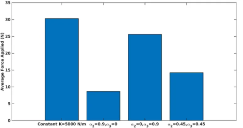
experimental parameters in Table I we performed experiments for different values of α2 and α3. The results are shown
in Fig.5 and Fig.6 . In the first strategy we gave complete weightage to the force performance i.e α2= 0.9, α3 = 0. In
the second strategy we gave complete weightage to the time performance i.e α2 = 0, α3 = 0.9. In the third strategy we
gave equal weightage to both force and time performance i.e α2 = 0.45, α3 = 0.45. The users were informed about the
strategy before each experiment. With the first strategy the users gave the best force performance while simultaneously taking the longest time for task completion. The force per-formance with this strategy was the best. This is obvious as if time is not a criteria then the user can perform the task slowly and comfortably with great accuracy. With the second strategy the users applied huge forces to complete the task in minimum time while committing many faults. But as the time performance was very good so the penalty (Xpenalty=-0.4)
was not sufficient to restrict the user to the first band (highest robot stiffness) to ensure high accuracy. The time performance with the second strategy was the best. The third strategy gave a good result of both force and time performance, although lesser than the first and second strategies respectively. But the result was better than the reference. The force performance bands and the robot stiffness policy is specific to the user and if another person is taken as the reference then the robot stiffness policy has to be redesigned.
Fig. 5. Comparison of Average Forces applied by the users in different strategies
Fig. 6. Comparison of Task Completion Time for different strategies
It should be noted that for the proposed methodology to work for another type of task there should be a relation between the task performance and the parameter to be tuned (in this work it was the robot stiffness) and also the task performance should lie in clearly distinguishable discrete bands.
CONCLUSIONS ANDFUTUREWORK
In this paper we demonstrated a novel trust-based impedance control scheme based on task performance metrics and faults that allow a robot to act as a supervisor for its human partner in a cooperative human-robot task. This methodology can be used to integrate task metrics into an impedance/admittance control scheme for other type of co-operative human-robot tasks. It also shows in a preliminary manner how a novice user’s performance can be compared
to that of a professional for the same type of task. For our future work we will perform the same type of experiment for variable admittance control and also change the task from a cooperative to a collaborative one.
ACKNOWLEDGMENT
This work is funded by the French Government through the FUI Program (20th call with the project AEROSTRIP).
REFERENCES
[1] Dumora, J., Geffard, F., Bidard, C., Brouillet, T. and Fraisse, P., 2012, October. Experimental study on haptic communication of a human in a shared human-robot collaborative task. In 2012 IEEE/RSJ International Conference on Intelligent Robots and Systems (pp. 5137-5144). IEEE. [2] Erden, Mustafa Suphi, and Bobby Mari. ”Assisting manual welding with
robot.” Robotics and Computer-Integrated Manufacturing 27.4 (2011): 818-828.
[3] Wojtara, T., Uchihara, M., Murayama, H., Shimoda, S., Sakai, S., Fujimoto, H. and Kimura, H., 2009. Humanrobot collaboration in precise positioning of a three-dimensional object. Automatica, 45(2), pp.333-342.
[4] Hogan, N., 1984, June. Impedance control: An approach to manipula-tion. In 1984 American control conference (pp. 304-313). IEEE. [5] Ikeura, R., Monden, H. and Inooka, H., 1994, July. Cooperative motion
control of a robot and a human. In Proceedings of 1994 3rd IEEE International Workshop on Robot and Human Communication (pp. 112-117). IEEE.
[6] Ikeura, R. and Inooka, H., 1995, May. Variable impedance control of a robot for cooperation with a human. In Proceedings of 1995 IEEE International Conference on Robotics and Automation (Vol. 3, pp. 3097-3102). IEEE.
[7] Rahman, M.M., Ikeura, R. and Mizutani, K., 1999. Investigating the impedance characteristic of human arm for development of robots to co-operate with human operators. In IEEE SMC’99 Conference Proceedings. 1999 IEEE International Conference on Systems, Man, and Cybernetics (Cat. No. 99CH37028) (Vol. 2, pp. 676-681). IEEE. [8] Tsumugiwa, T., Yokogawa, R. and Hara, K., 2002. Variable impedance
control based on estimation of human arm stiffness for human-robot cooperative calligraphic task. In Proceedings 2002 IEEE International Conference on Robotics and Automation (Cat. No. 02CH37292) (Vol. 1, pp. 644-650). IEEE.
[9] Ikeura, R., Moriguchi, T. and Mizutani, K., 2002. Optimal variable impedance control for a robot and its application to lifting an object with a human. In Proceedings. 11th IEEE International Workshop on Robot and Human Interactive Communication (pp. 500-505). IEEE. [10] Peternel, L., Tsagarakis, N. and Ajoudani, A., 2016, October. Towards
multi-modal intention interfaces for human-robot co-manipulation. In 2016 IEEE/RSJ international conference on intelligent robots and sys-tems (IROS) (pp. 2663-2669). IEEE.
[11] Duchaine, V. and Gosselin, C.M., 2007, March. General model of human-robot cooperation using a novel velocity based variable impedance control. In Second Joint EuroHaptics Conference and Sym-posium on Haptic Interfaces for Virtual Environment and Teleoperator Systems (WHC’07) (pp. 446-451). IEEE.
[12] Itoh, M. and Tanaka, K., 2000, July. Mathematical modeling of trust in automation: Trust, distrust, and mistrust. In Proceedings of the human factors and ergonomics society annual meeting (Vol. 44, No. 1, pp. 9-12). Sage CA: Los Angeles, CA: SAGE Publications.
[13] Lee, J. and Moray, N., 1992. Trust, control strategies and allocation of function in human-machine systems. Ergonomics, 35(10), pp.1243-1270. [14] Hancock, P.A., Billings, D.R., Schaefer, K.E., Chen, J.Y., De Visser, E.J. and Parasuraman, R., 2011. A meta-analysis of factors affecting trust in human-robot interaction. Human factors, 53(5), pp.517-527.
[15] Walker, I.D., Mears, L., Mizanoor, R.S., Pak, R., Remy, S. and Wang, Y., 2015, August. Robot-human handovers based on trust. In 2015 Second International Conference on Mathematics and Computers in Sciences and in Industry (MCSI) (pp. 119-124). IEEE.
[16] Saeidi, H. and Wang, Y., 2015, December. Trust and self-confidence based autonomy allocation for robotic systems. In 2015 54th IEEE Conference on Decision and Control (CDC) (pp. 6052-6057). IEEE.