The Design and Implementation of inTouch:
A Distributed, Haptic Communication System
Victor C. SU
Bachelor of Science, Massachusetts Institute of Technology, Cambridge, Massachusetts, June 1998
Submitted to the Department of Electrical Engineering and Computer Science in Partial Fulfillment of the Requirements for the Degree of
Master of Engineering in Electrical Engineering and Computer Science at the Massachusetts Institute of Technology
February 3, 1999
@ 1999 Victor C. Su. All rights reserved.
The author hereby grants to M.I.T. permission to reproduce and distribute publicly paper and electronic copies of this thesis
and to grant others the right to do so.
Author
Certified by
Department of Electrical Engineering and Computer Science February 3, 1999 / Accepted by Hiroshi Ishii Thesis Supervisor L. - / -Arthur C. Smith Chairman, Department Committee on Graduate Theses
ENO
The Design and Implementation of inTouch:
A Distributed, Haptic Communication System
Victor C. Su
Submitted to the
Department of Electrical Engineering and Computer Science February 3, 1999
In Partial Fulfillment of the Requirements for the Degree of Master of Engineering in Electrical Engineering and Computer Science
Abstract
The inTouch project explores the notion of haptic interpersonal communication. Using bilateral force-feedback to couple two physically separated nodes, inTouch provides a
channel for expression through touch. This interaction is derived from the concept of synchronized, distributed physical objects. This document explains the design and implementation of a self-contained, microcontroller-based version of inTouch. The structure of the system described here is intended to serve as an example of this concept as it relates to interpersonal communication and as a starting point to incorporating tactile channels into communication technologies.
Thesis Supervisor: Hiroshi Ishii
Acknowledgements
I would like to thank Scott Brave and Andrew Dahley for their original idea of inTouch as well as Phil Frei for his effort in designing the mechanical system. I am also grateful to Chris Leung and Rujira Hongladaromp for their work in the production run. Most of all, I would like to thank Professor Hiroshi Ishii for his support and encouragement.
Table of Contents
ABSTRACT ...-...---... 2 ACKNOWLEDGEMENTS...---...3 TABLE OF CONTENTS ...---... 4 TABLE OF FIGURES ...-- .. ..---... 6 1 INTRODUCTION... ...-....-.---... 8 1.1 D ESIGN CONCEPTS ...--- ....-- .... - -... . ---... 8 1.2 R ELATED W ORK ...- ...----....- -.. ---... 92 EVOLUTION OF THE DESIGN... 11
2.1 MECHANICAL MODEL: INTOUCH-0 ... 11
2.2 SINGLE COMPUTER VERSION: INTOUCH-1 ... ... 11
2.3 DISTRIBUTED COMPUTER VERSION: INTOUCH-2... 12
2.4 EMBEDDED CONTROL VERSION: INTOUCH-3 ... ... 14
3 HARDWARE IMPLEMENTATION... 14
3.1 O VERVIEW ...- -.... ---... 14
3.2 MICROCONTROLLER SELECTION... 15
3.3 ENCODER READER...---... 15
3.4 ENCODER TO MICROCONTROLLER INTERFACE ... 18
3.5 M OTOR CONTROLLER... ... ---... 20
3.5.1 P W M M otor D rive ... ... ---... 20
3.5.2 H -B ridge C ircuit ... ... - .... ---... 21
3.5.3 Initial Tests of Open-Loop Current Control ... 23
3.5.4 Closing the Loop: The PWM Servo Controller... 26
3.5.5 The Com m ercial Solution ... 28
3.6 DIGITAL-TO-ANALOG CONVERTER ... 29
3.7 DATA COMMUNICATIONS INTERFACE ... 30
3.8 POW ER SUPPLY... ... --... -... ---... 33
3.9 MECHANICAL UNIT INTERFACE... 35
3.10 FAULT RECOVERY AND TROUBLESHOOTING ... 36
4 THE INTOUCH CONTROL ALGORITHM ... 37
4.1 MECHANICAL SUBSYSTEM ... ...-- - - 37
4.2 CONTROL LOOP ...- --- --- ----. - --- ---... 38
4.3 PID CONTROLLER ...---...- -. - --- ---- ---- ---- ----... 39
4.3.1 Theory ...----... --... ---... 40
4.3.2 Discrete-Time Implementation... ... 44
4.3.3 Frequency-D om ain Analysis... 45
4.4 SYSTEM ANALYSIS MODELS... 46
4.4.1 Single-Node Model with Zero Disturbance Torque... 46
4.4.2 Single-Node Model with Zero Reference Input... 48
4.4.3 Zero D elay M odel ... -...-... 50
4.4.4 N on-Zero D elay M odel ... 53
4.5 INTERACTION D YNAM ICS ... ... - . ---... 55
4.6 ADJUSTMENT OF ALGORITHM PARAMETERS ... 56
5 PRODUCTION...-..----....---... 57
5.1 PCB LAYOUT AND MANUFACTURING ... ..-... 58
5.3 C O N TRO L BoL B...--...----.... ---...---. 6 1
5.4 CABLING ... . ...-... 62
5.5 ASSEMBLY AND TESTING ... 63
6 MODEM INTERFACE UNIT... 63
6.1 O V ERV IEW ... ... --.. .. ---... 63
6.2 T IM ING AND D ELAY ...- ... ---.... ---... 64
6.3 HARDWARE IMPLEMENTATION... 64
6 .3 .1 S eria l P o rts ... 6 5 6.3.2 L C D D isp lay ... 6 7 6.3.3 N um eric K eyp ad ... 68
6.3.4 SPI Bus Address Decoder ... 69
6.4 FIRMWARE IMPLEMENTATION ... 70
6.4.1 M odem C ontroller ... 70
6.4.2 Keypad Input Parser and Display... ... 71
6.4.3 C onnection Typ es...----...--.--- 71
6.4.4 D ata R outing ... 72
6.5 T EST R ESULTS ...---... -.. ---... 73
7 OTHER ACCESSORIES...---... 75
7.1 PORT ADAPTER... - ... 75
7.2 D ELAY SIM ULATOR ...- ... ---.-. --. --. --... 75
7.3 R ECORD IN G D ATA ...---...---... 76
8 FUTURE WORK...---... 77
8.1 CUSTOM SERVO AMPLIFIER... 77
8.2 POWER SUPPLY ISOLATION... 78
8.3 CONTROLLER BOARD SYNCHRONIZATION... 79
8.4 DELAY COMPENSATION... 80
8.5 MULTI-NODE CONFIGURATION ... 81
9 CONCLUSIONS ... ... ... 82
Table of Figures
FIGURE 1.1: OBJECT-MEDIATED COMMUNICATION... 9
FIGURE 1.2: INTOUCH CONCEPTUAL SKETCH... 9
FIGURE 2.1: INTOUCH-0 ... 11
FIGURE 2.2: M ECHANICAL SUBSYSTEM OF INTOUCH-1 ... 12
FIGURE 2.3: SYSTEM ARCHITECTURE OF INTOUCH-1... 12
FIGURE 2.4: MECHANICAL SUBSYSTEM OF INTOUCH-2 ... 13
FIGURE 2.5: SYSTEM ARCHITECTURE OF INTOUCH-2... 13
FIGURE 2.6: SYSTEM ARCHITECTURE OF INTOUCH-3... .... 14
FIGURE 3.1: FUNCTIONAL DIAGRAM OF THE INTOUCH-3 SYSTEM ... 15
FIGURE 3.2: QUADRATURE WAVEFORM OF ENCODER [16] ... 16
FIGURE 3.3: SCHEMATIC OF DIRECTION SENSING CIRCUIT ... ... 17
FIGURE 3.4: ACCOUNTING FOR COUNTER ROLL-OVER ... 18
FIGURE 3.5: HARDWARE PRESCALING OF THE ENCODER CLOCK... 19
FIGURE 3.6: PW M WAVEFORMS FOR VARYING DUTY CYCLES [20]. ... 20
FIGURE 3.7: H-BRIDGE CIRCUIT... ... - - -... 2121.- FIGURE 3.8: TORQUE AS A FUNCTION OF DUTY IN PW M DRIVE... .. 24
FIGURE 3.9: SIGN/MAGNITUDE PWM DRIVE [17]... 24
FIGURE 3.10: LOCKED ANTI-PHASE PWM MODULATION [17]... 27
FIGURE 3.11: MODIFIED FUNCTIONAL BLOCK DIAGRAM OF INTOUCH-3 SYSTEM ... 28
FIGURE 3.12: CHARGE PUMP NEGATIVE VOLTAGE CONVERTER... 30
FIGURE 3.13: RS-232 SERIAL BYTE WAVEFORM [8] ... 31
FIGURE 3.14: STEP-DOWN SWITCHING REGULATOR CIRCUIT ... 35
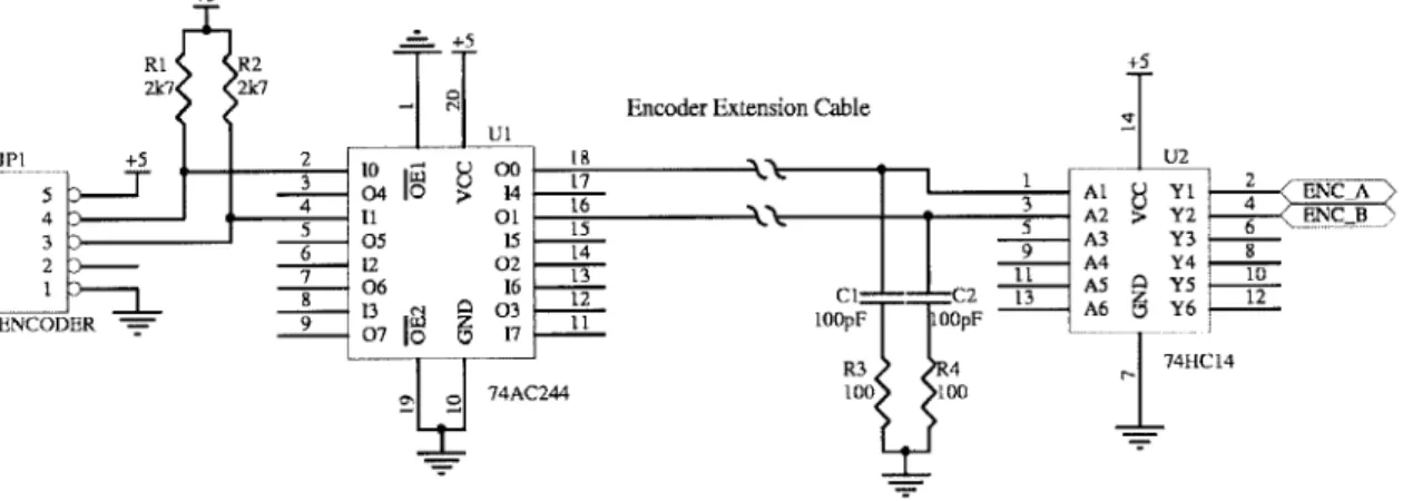
FIGURE 3.15: EXTENDING THE ENCODER CABLE LENGTH ... ... 36
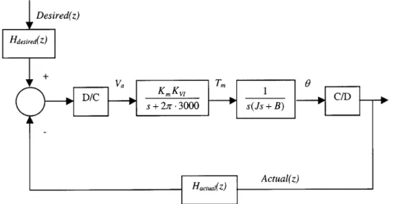
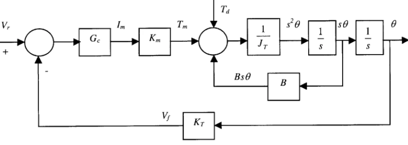
FIGURE 4.1: BLOCK DIAGRAM OF MECHANICAL SUBSYSTEM AND CONTROLLER ... 37
FIGURE 4.2: SYSTEM TRANSIENT RESPONSE ATTRIBUTES [6] ... 40
FIGURE 4.3: UNIT STEP RESPONSE OF A CRITICALLY DAMPED SYSTEM [6]... 41
FIGURE 4.4: GAIN AND PHASE MARGINS OF OPEN-LOOP TRANSFER FUNCTION [6]... 42
FIGURE 4.5: BLOCK DIAGRAM OF THE PID CONTROLLER ... 46
FIGURE 4.6: SINGLE-NODE, ZERO DISTURBANCE TORQUE MODEL ... 47
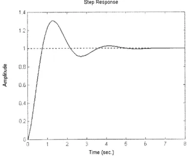
FIGURE 4.7: STEP RESPONSE OF THE SINGLE-NODE, ZERO DISTURBANCE TORQUE MODEL... 48
FIGURE 4.8: SINGLE-NODE, ZERO REFERENCE INPUT MODEL... 49
FIGURE 4.9 IMPULSE RESPONSE OF THE SINGLE-NODE, ZERO REFERENCE INPUT MODEL ... 50
FIGURE 4.10: INTOUCH-3 SYSTEM BLOCK DIAGRAM ... 51
FIGURE 4.11: SYSTEM DIAGRAM FOR ANALYSIS OF THE ZERO DELAY MODEL ... 51
FIGURE 4.12: BLOCK DIAGRAM OF ZERO DELAY MODEL ... 52
FIGURE 4.13: IMPULSE RESPONSE OF THE TWO-NODE ZERO DELAY MODEL ... 53
FIGURE 4.14: BLOCK DIAGRAM OF NON-ZERO DELAY MODEL ... ... 54
FIGURE 4.15: IMPULSE RESPONSE OF THE TWO-NODE, NON-ZERO DELAY MODEL... 55
FIGURE 5.1: CONTROLLER BOARD... 58
FIGURE 5.2: ASSEMBLED CONTROLLER UNIT... 59
FIGURE 5.3: AUXILIARY BOARD ...-- ...--- .. . ---... 60
FIGURE 5.4: AUXILIARY BOARD MOUNTED TO THE MECHANICAL UNIT ... 60
FIGURE 5.5: INTOUCH-3 SYSTEM CONNECTIONS ... 62
FIGURE 6.1: SERIAL MULTIPLEXER/DEMULTIPLEXER SYSTEM CONNECTIONS (A) AND DATA FLOW (B). ... 65
FIGURE 6.2: MULTIPLE EXTERNAL SERIAL PORTS... 66
FIGURE 6.3: MAX208 FOUR CHANNEL RS-232 LEVEL CONVERTER ... 67
FIGURE 6.4: SPI-INTERFACED CHARACTER LCD... .. 68
FIGURE 6.5: SPI-INTERFACED KEYPAD... 69
FIGURE 6.6: SPI BUS ADDRESS DECODER ... 69
FIGURE 6.7: MODEM INTERFACE BOARD ... -... ... 74
FIGURE 7.1: PORT ADAPTER ...- .. --- ... - - . ---... 75
FIGURE 8.1: GENERATING AN ANALOG VOLTAGE FROM THE PWM OUTPUT ... 77
FIGURE 8.3: CONTROLLER BOARD CONFIGURATION FOR SYNCHRONIZATION... 79
FIGURE 8.4: TIMING DIAGRAM FOR INTOUCH-3 SYNCHRONIZATION ... 79
FIGURE 8.5: FOUR-NODE RING TOPOLOGY... 81
1
Introduction
The goal of any communication technology is to bridge the distance between people by extending the senses through some transmission medium. Current communication technologies, such as the telephone or the videophone, appeal exclusively to the visual and auditory senses. Furthermore, work in the field of telepresence research has focused on the visual and auditory extension of space [10]. What has largely been unexplored, however, is the sense of touch, especially communication by touch. In everyday situations, touch plays an important role in the relations between people. A handshake, a pat on the back, and a warm embrace are all examples of physical
expression of emotion. At times, these actions are more compelling and expressive than words. The goal of this project is thus to study new forms of interpersonal
communication by touch, and how a simple implementation of this concept may serve as a starting point for incorporating tactile channels into future communication technologies.
This chapter will describe the conceptual framework behind inTouch along with some related work. Chapter 2 will introduce several versions of the inTouch system prior to the implementation of inTouch-3. Chapter 3 will examine the hardware development of inTouch-3 and will be followed by a discussion of the control algorithm in Chapter 4. Chapter 5 describes the production effort of 10 sets of this system. Chapter 6 introduces the design and implementation of the main accessory to the system, the modem interface unit. Chapter 7 describes several other accessories designed for the inTouch-3. Finally, Chapter 8 will outline several areas of future work and will be followed by the conclusion in Chapter 9.
1.1 Design Concepts
Haptic interpersonal communication aims to allow distant users to sense each other's presence. Ideally, all tactile information should be transmitted to achieve this, but this
feat is currently beyond the state of the art. Instead, the concept of a "shared physical object," as illustrated in Figure 1.1, is used. If two people manipulate a common object,
then they can communicate hapticly and sense each other's presence, as shown in (a). If the object is instead separated and linked by some sort of communication technology, then the illusion of a unified object can be created, as shown in (b). This is the concept of a synchronized, distributed physical object.
a) shared physical b) synchronized distributed
object physical objects
Figure 1.1: Object-mediated communication
InTouch is an example of this concept and was designed by Media Lab graduate students Scott Brave and Andrew Dahley. A conceptual sketch is shown in Figure 1.2. The physical structure of inTouch consists of a set of three cylindrical, wooden rollers
embedded in a metal base. The rollers are hapticly coupled so that each roller behaves as though it were physically linked to its corresponding roller on the other unit.
Interactions between users can include passively feeling the presence of the other, moving the object cooperatively, or fighting over the state of the rollers.
Figure 1.2: inTouch conceptual sketch
1.2 Related Work
Current haptic research deals with the creation of virtual objects with form, mass, and texture, and the force-feedback devices that allow them to be felt. An example is the PHANTOM by SensAble Technologies. In these systems, the force-feedback device acts
as a portal to the virtual world. InTouch, in contrast, does not link users to virtual worlds, but to each other.
Although inTouch is decidedly a device that links physical spaces to physical spaces, an example from the virtual world can still be referred to in this discussion. In most
virtual environments, a single user interacts with virtual objects as though they had physical form. A scenario where more than one user interacts with the same virtual
object, however, illustrates the concept of inTouch. In this case, the virtual
environment serves as a mediator between physical spaces, connecting them like the inTouch.
In contrast to virtual reality research, tactile communication involves the extension of one's physical presence across distance. It is related to the field of tele-operation, which allows the operator to control a slave device such as a robot from a remote location. To facilitate the operator's control of the device, the forces exerted on it are reproduced at the point of control in a sort of feedback loop, giving the operator a tactile sense of the object under manipulation [7]. If the device under tele-operative control is not a slave robot but another operator, then a device similar in concept to the inTouch is created. Although tele-operation might be a plausible solution, it was not intended for the function of interpersonal communication, so a more elegant solution is desired.
Although few in number, there has been some previous work related to communication by touch. One such project is Feather, Scent, and Shaker [22] in which a pair of
"shaker" objects is linked so that movement of one causes the other to vibrate and vice-versa.
Another project is HandJive [4], which allows the playing of haptic games through a pair of hand-held objects. The object consists of a shaft resembling a joystick, which when moved from side to side, causes a corresponding object to move up and down. The
difference between HandJive and inTouch is that the HandJive devices are not tightly coupled. The input and output space exist on the same device, but are distinct. The design was so chosen to prevent "fighting" over the device. This "fighting," however, is fundamental to the concept behind inTouch.
A third project, which demonstrates the use of bilateral force-feedback in interpersonal communication, is Kinesthetic Constructions [21]. Kinesthetic Constructions employs a
network of large modem sculptures distributed around the world. Parts of each sculpture are connected to other sculptures hapticly.
2 Evolution of the Design
2.1 Mechanical Model: inTouch-0
Three versions of inTouch existed prior to the work documented in this thesis. The first version, inTouch-0, was a mechanical mock-up that served as a proof of concept and is
shown in the illustration below. The rollers are connected together by stiff flex shafts.
Figure 2.1: inTouch-0
2.2 Single Computer Version: inTouch-1
InTouch- 1 developed as the first electronic prototype of the inTouch concept. The mechanical subsystem was designed by Phil Frei, a mechanical engineering student, and is shown below. The rollers are driven by precision, permanent-magnet DC motors made by Maxon, and are commonly used in force-feedback applications. Coupled to the drive shaft of each motor is a digital rotary encoder, which is used to track position. The encoder, made by Hewlett-Packard, has a resolution of 500 lines per revolution, which provides for position accuracy to about three-quarters of a degree of arc. Each roller is driven at a gear ratio of four to one, and thus 2000 lines of resolution are possible per revolution of the roller.
Figure 2.2: Mechanical subsystem of inTouch-1
The electrical subsystem consisted of a set of Impulse motor control boards,
manufactured by Immersion Corporation. These motor control boards interfaced to the computer through PCI bus cards, and were programmed through C++ libraries provided by Immersion. The system architecture of inTouch-1 is shown here.
Maxon motors /
HP encoders PCI cards
encoder count control boards
Figure 2.3: System architecture of inTouch-1
From this point forward, a node will refer to the combined electrical and mechanical subsystems, and represents an abstracted self-contained interaction unit. The diagram above thus illustrates that both nodes are controlled by algorithms running on a single computer, hence the name single computer version.
2.3 Distributed Computer Version: inTouch-2
For the third-generation version of inTouch, the mechanical subsystem was further refined by Phil Frei to the unit shown below. The motors have been encased in the left side of the unit and the shape made to conform to the placement of the rollers. This improves the aesthetic appearance of the unit and invites the touch.
Figure 2.4: Mechanical subsystem of inTouch-2
The control algorithms of inTouch- 1 were distributed symmetrically over two computers so that the nodes could communicate over a local area network by passing position information using universal datagram protocol (UDP). With this addition,
communication latency became an issue, and because inTouch is a bilateral feedback system, obviously led to particularly undesirable effects such as system instability. These effects will be examined in the sections to follow. The distributed architecture
system is shown here.
Maxon motors HP encoders. force connection encoder count Immersion control boards
Figure 2.5: System architecture of inTouch-2
The system was tested using the Media Lab network and performed essentially identically to inTouch- 1 as long as delay remained small. 'Typical network delays for transmission within the Media Lab are approximately two milliseconds. For moderate delays, compensation techniques such as velocity prediction permitted stable operation to approximately 12 milliseconds. For delays exceeding 12 milliseconds, noise present in the system prevented accurate prediction.
As an alternative means of compensation, low pass filtering was attempted. Since the interaction frequency (the frequency at which the rollers are moved forward and
backward) does not usually exceed five hertz, low pass filtering can reduce unwanted high frequency oscillation at the expense of tactile sensitivity. This filtering technique proved to be effective for delays up to 40-milliseconds [2].
2.4 Embedded Control Version: inTouch-3
This thesis documents the development of the fourth-generation inTouch system, inTouch-3. The goal of inTouch-3 is a self-contained, embedded control system, which implements the inTouch algorithm in custom hardware and firmware, and does not require the use of a computer. Communication between nodes complies with the RS-232C standard for serial communications, which permits future additions such as modules for modem communication as well as an interface to a computer-based
simulator. The system architecture of inTouch-3 is shown below.
Maxon motors/ HP encoders force connection encoder count
~47ftniouj
MCU-based control boardsFigure 2.6: System architecture of inTouch-3
3 Hardware Implementation
3.1 Overview
The hardware implementation was accomplished first so that the control firmware could later be developed on a stable hardware platform. This thesis documents the
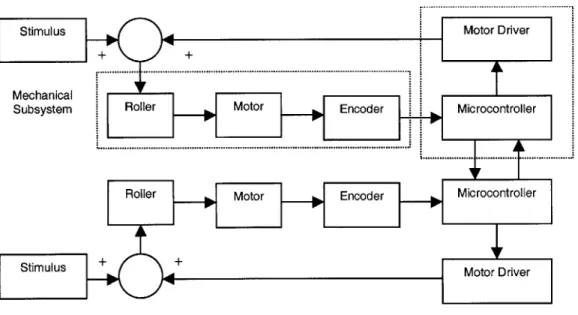
development of the electrical subsystem of inTouch-3, since the mechanical subsystem is unchanged from inTouch-2. The functional blocks of the inTouch-3 system are shown below.
Electrical
Mechanical Subsystem
Subsystem Roller Motor Encoder Microcontroller
Roller Motor Encoder Microcontroller
Stimulus + +Motor Driver
Figure 3.1: Functional diagram of the inTouch-3 system
The stimulus represents the users' input to the mechanical unit. This external torque acts on the rollers, which are coupled to the motors. The motor shaft is in turn coupled to a rotary encoder. The microcontroller, serving as the control core, reads the encoder position and transmits it to the remote node. The microcontroller then executes the inTouch synchronization algorithm on the encoder position received from the remote node as well as its own position and outputs an appropriate control signal, which the motor driver converts to current to drive the motor.
3.2 Microcontroller Selection
The PIC 16C73A microcontroller made by Microchip Technology, Inc., was selected for the controller core. This microcontroller can operate at high speed (20 MHz), and can thus provide ample processing power to implement the inTouch synchronization algorithm. Moreover, the PIC is inexpensive and has an efficient RISC instruction set and Harvard architecture. The microcontroller also offers several attractive features such as serial communications hardware and a full set of interrupts.
The first module to design in the inTouch-3 system was the rotary encoder reader used to track the position of the roller. The output of the encoder is a quadrature logic signal as shown in Figure 3.2. Note that the Phase A and Phase B waveforms differ in phase by 90 degrees. IN is an index pulse generated by the encoder once per revolution and can be used track absolute position. The index pulse is not used in inTouch since only relative positions are necessary, as will be apparent in the discussion of the algorithm.
A
B
fi-N
T3 T3
1NDEX=AX@iieW
Figure 3.2: Quadrature waveform of encoder [16]
If the outputs of the encoder are considered as digital values, a sequence {00, 01, 11, 10, 00...) known as gray code is produced. The defining characteristic of gray code is that only one bit changes between code words, which prevents logic race conditions during code word transitions. The two sequences shown below illustrate the output from the encoder lines in each direction of rotation. The sequences should be read from top to bottom.
Bit A Bit B Bit A Bit B
0 0 0 0
0 1 1 0
1 1 1 1
1 0 0 1
0 0 0 0
Table 3.1: Code sequences of quadrature encoder for each direction of rotation
Using the exclusive OR operator on bit A of one code word (for example the 0 in 01) with bit B of the following code word (the right 1 in 11), 1 is produced in one direction, while
0 is produced in the other. Thus, quadrature output is used to determine direction of shaft rotation.
The direction sensing described above may be implemented in software as firmware on the microcontroller or as hardware as a connection of two flip-flops. In the interest of reducing processing overhead on the microcontroller, the hardware implementation was chosen and is shown in Figure 3.3.
+5 U1A
9
> LK 8
12 13 CLRD
Figure 3.3: Schematic of direction sensing circuit
A digital counter maintains the encoder's position and is clocked from either phase A or phase B of the encoder. The choice is arbitrary. The output of the direction sensing circuit indicates the rotation direction and may be used to decide whether to increment or decrement the counter.
Again, the design choice here for the counter may be implementation in software or hardware. Necessary features of the counter include moderate to high resolution and bi-directional clocking. The latter condition is necessary since the inTouch application
demands tracking of the roller in both directions. While up/down hardware counters are available (for example, the 74HC 193), a software counter was chosen since it provides for easy changes to the resolution of the counter, and implementation of bidirectionality is simpler.
The software counter used in inTouch possesses only eight bits of resolution. To address the problem of counter roll-over when determining the change in position between counter values, a "shortest distance" method was used. The 8-bit counter takes on values from zero to 255 and is unsigned. Therefore, incrementing the counter at 255 results in a value of zero and decrementing it at zero results in a value of 255.
For discussion, assume a starting counter value of zero. If the next value is between zero and 127, the midpoint, then it is assumed that the encoder has moved in the positive direction from zero to that given value. If the next value is between 128 and 255, then it is assumed that the encoder has moved in the negative direction from 0 to that given value, rolling backwards to 255. To generalize for arbitrary starting values, the difference between counter values is used. If the difference between two successive
counter values is less than 127, then the positive direction is assumed. If it is greater than 127, then the negative direction is assumed. Similarly, if the difference is greater than -127, then the negative direction is assumed. If it is less than -127, then the positive direction is assumed. This method is illustrated in Figure 3.4.
255
These values are assumed to These values are assumed to indicate rotation in the indicate rotation in the
"negative" (decrementing) "positive" (incrementing)
direction. direction.
127
Figure 3.4: Accounting for counter roll-over
3.4 Encoder to Microcontroller Interface
There are two options for designing the interface between the encoder and the
microcontroller. The microcontroller can poll the encoder to watch for changes in the encoder clock. This scheme, however, has the disadvantage that it requires substantial processing overhead, especially if the motor shaft is moving at high speed. In this case, the microcontroller must poll the encoder at least as fast as the expected rate of
encoder change. Since the inTouch system uses high-resolution encoders at a
moderate gear ratio, very small movements of the roller will result in encoder changes, so a high polling rate would be required.
An alternative solution to polling is to take advantage of the interrupt capabilities of the PIC microcontroller. The encoder clock may be connected to the external (EX)
interrupt of the microcontroller, which is executed on either the rising or falling transitions of the RBO pin (the edge is software selectable). This allows the PIC to
execute other code in the time saved from not having to poll the encoder for changes. The interrupt service routine (ISR) for the EXT interrupt may thus examine the direction
output from the encoder hardware and increment or decrement the software counter as appropriate.
An additional feature of the encoder to microcontroller interface that was not included in the final design is prescaling of the encoder clock. The objective of prescaling is to
reduce the resolution of the encoder by eliminating clock pulses. Prescaling may be performed either in software by ignoring every other or every third clock pulse, for instance, or in hardware with a simple counter as shown in Figure 3.5. The outputs of the counter provide powers-of-two divisions of the encoder clock.
+5 U1 T 16 |VCC Q1 9 ENCC L K Q2 67 ENCCLK/12'> Q3 -5F- EN~iR 10 3 <-ENCCLK7 '; >CLK Q5 2 Q6 4 11 Q7 13 RESET Q8 12 Q9 14 Q10 1 8 Qi1 1 GND Q12 74HC4040
Figure 3.5: Hardware prescaling of the encoder clock
Prescaling might be used to reduce the resolution of the encoder when rotation speeds are too high. Assuming the interrupt clocking scheme described above, it is observed that there is a maximum clocking frequency that can be handled by the microcontroller. This is a function of both the instruction overhead necessary to service the interrupt as well as the execution time of the ISR code itself. Moreover, it is undesirable to have the interrupt service routine executing so frequently that other interrupts or the main loop
of the program cannot be executed. Ultimately, the maximum clocking frequency is dependent upon the clock speed of the microcontroller. If prescaling is being used for this purpose, then hardware implementation is more sensible since reducing the encoder resolution prior to interfacing with the microcontroller will reduce execution frequency of the interrupt service routine.
3.5 Motor Controller
The next developmental block in the functional diagram is the motor driver hardware. Motor control may be divided into three main areas: torque control, velocity control, and position control. These three types of control are best implemented as closed loop systems, as the discussion here will show. Torque control requires current sensing hardware, which will be discussed in Section 3.5.2. Velocity control is typically
performed by coupling a tachometer to the motor shaft, producing a voltage proportional to angular velocity. Position control may be achieved using a rotary encoder, which produces a quadrature pulse train as described in Section 3.3, or a simple potentiometer, which produces a varying voltage with respect to position.
InTouch requires both torque control for force-feedback and position control to maintain positional consistency of the rollers. Position control is achieved in the firmware of the microcontroller, using input from the encoder reader described in the last section, and will be discussed in more detail in sections to follow. Torque control will be examined here.
3.5.1 PWM Motor Drive
The initial design of the torque controller employed a scheme known as pulse-width modulation (PWM). In PWM, the pulse width, also known as the duty cycle, is varied between zero and 100 percent of the waveform's period. In this way, the time in which the waveform is logical HIGH is varied from zero, at zero duty cycle, to the whole period, at 100 percent duty cycle. Note that in the limiting cases zero and 100 percent, the waveform is constant. Figure 3.6 shows PWM waveforms for 25, 50 and 75 percent duty cycles. Another parameter of PWM is the switching frequency, which is the frequency at which a high pulse and a low pulse occur (with the exception of the limiting cases). The inverse of the frequency is the PWM period.
50% duty cycle 75% duty cycle 25% duty cycle
If the PWM waveform is connected to the gate of a transistor, it may be used to vary the voltage at its terminals in proportion to the duty cycle, and do so very efficiently. Since the PIC microcontroller includes on-chip hardware PWM generators, they can be used for motor control with the added feature that essentially no software overhead is incurred in generating these waveforms.
3.5.2 H-Bridge Circuit
Although PWM can generate an analog voltage when used with a transistor as will be shown in the next section, the problem of how those transistors should be connected to drive motors must still be addressed. One desirable feature is that the circuit should only need one voltage supply, although motor drive should be possible in both
directions. A configuration known as an H-bridge, Figure 3.7, provides the answer.
Cl +12 470uF Q D D2PWM2 MOSFET Q2 PWMt M1 Q2 MOSFET N OUTPUT1 VOl V02 OUTPUT2
Q3 MOTOR PWM1)
MOSFET D3 D4
PWM2 MOSFET N
Vsense
R1
Figure 3.7: H-bridge circuit
Notice that when the upper left and the lower right transistors are switched on by applying sufficient voltage to PWM 1, current flows through the motor in the left to right direction. When the upper right and the lower left transistors are switched on by applying sufficient voltage to PWM2, current flows through the motor in the right to left direction. Thus, by choosing the appropriate pair of transistors to drive, bidirectional motor drive can be achieved with only a single voltage supply. Because the H-bridge
circuit is used to drive inductive loads such as motors, protection diodes are added across the transistors to protect them from inductive reverse current. Note that the H-bridge shown above includes a current sensing resistor in the main current path. The resistor produces a voltage (Vsense) proportional to the current flowing through the bridge and thus can be used for current feedback control.
Rather than switching both transistors on each PWM cycle as described above, one terminal of the motor can be held at a fixed potential by turning on the upper transistor in that branch and turning on the lower transistor of the other branch during the on period and the upper transistor during the off period. The voltage at the other terminal of the motor is thus the time-average voltage as function of the duty cycle. The purpose
of this method of drive is to prevent the motor from slipping during the PWM off time. During this portion of the waveform, both of the upper transistors in the H-bridge are switched on, creating a low impedance path between the motor terminals. This
presents a particular problem for inTouch because the low impedance path means that the motor behaves as a generator under free rotation of the shaft. The induced voltage causes current to flow through this closed path around the motor terminals in a direction that resists the motion. To compensate for this "inductive friction" effect, the inTouch control algorithm, which will be discussed in Chapter 4, drives the motor slightly by an amount dependent upon velocity and thereby reduces the perceived friction.
Returning to Figure 3.7, it is seen that MOSFET's are typically used for H-bridge transistors. Field-effect transistors have essentially no gate current, and thus are easy to drive with logic. An enhancement mode n-channel MOSFET will turn on completely when its gate voltage is several volts above its source voltage. This does not present a problem for the transistors in the lower half of the bridge since their sources are referenced to ground. However, the sources of the upper pair of transistors in the H-bridge are referenced between ground and the supply voltage of the bridge, 12 volts, depending on whether those transistors are turned on. Therefore, under this
configuration, the gates of the upper pair of transistors must be switched from a voltage above the supply voltage of the bridge to ensure proper operation.
One possible solution is to switch to an alternate configuration where p-channel MOSFET's rather than n-channel MOSFET's are used for the two transistors in the upper half of the bridge. A p-channel MOSFET turns on when there is no voltage on the gate (to be precise, when the gate voltage is close to the voltage of the drain), and turns
off when it is several volts above. (Note that for p-channel devices, the source voltage is more positive than the drain voltage and for n-channel devices, the source is more
negative than the drain voltage.) With this modification, a logic inverter is needed to drive the p-channel MOSFET's from the PWM signal. This may be seen by noting that the p-channel MOSFET must be presented a logical LOW to turn on, while the
n-channel MOSFET must be presented with a logical HIGH. One problem with this modification is that p-channel devices tend to exhibit poorer performance than n-channel devices, manifested as higher gate threshold voltage, higher on resistance, and lower saturation current. This behavior results of the particulars of semiconductor physics. Specifically, in p-channel devices, the carriers are quantum holes rather than electrons, which have lower mobility and shorter lifetime [8].
Another solution is to return to the original configuration of all n-channel devices, but switch the transistors with a voltage that is higher than the supply voltage of the H-bridge. This higher voltage can be generated using a device known as a charge pump, which will be discussed in Section 3.6. While the H-bridge can be built with discrete components as in Figure 3.6, sometimes it is more convenient to use integrated circuits that also provide additional features not easily achievable with discrete
electronics. One example is the National Semiconductor LMD 18200. The LMD 18200 has a high current rating and built-in current sensing transistors to measure the amount of current flowing through the H-bridge. This device was chosen to implement the H-bridge in the initial tests described in the next section.
3.5.3 Initial Tests of Open-Loop Current Control
An initial test configuration was built and microcontroller code was written to sweep through the range of the duty cycle. The PIC was configured to produce 10-bit
resolution PWM (1024 values) at a switching frequency of 19.53 kHz. The PWM output was connected to the LMD 18200 to produce current at a supply voltage of 12 volts, the rating of the Maxon motor in the mechanical unit.
The results of the initial tests proved to be unsatisfactory as the PWM drive produced torque that was nonlinear with respect to duty cycle as shown in the figure here.
Figure 3.8: Torque as a function of duty in PWM drive
The stall current is the amount of current drawn by the motor with its rotors locked. The value shown in the graph is an 8-bit digital value acquired from the internal ADC of the microcontroller, mapped to an actual motor current range of 2.79 amperes. The largest data point is a value of 130, which corresponds to an actual current of about 1.4 amperes and is just slightly greater than the maximum continuous current limit of the Maxon motor. The current sense circuitry of the LMD 18200 and the transfer function of the ADC are assumed to be linear and monotonic. The horizontal axis is the 10-bit duty cycle of the microcontroller's PWM generator.
The observed behavior is a result of several factors, but first the operation of the LMD 18200 when used with PWM drive must be examined. The initial tests used sign/magnitude PWM drive as shown in Figure 3.9. In sign/magnitude drive, the magnitude is given by the PWM waveform, and the sign is given by a direction control line.
Sign/Magnitude PWM Control
C4RLCTIN 01.
FI14
1
FIJJ y1fu
UJ
f
MiOR SPEED: s-W
MEDON
AsT L 2W aLEDIN FASTAVRAr ruR7m row r;F XrRAT CURRFT F 0vs FRDW
OUPJT I TO RTU1 2 OUTPUT 2 70 WTUT
Figure 3.9: Sign/magnitude PWM drive [17]
140 120 4)100 80 S60 S40 20 0 0 200 400 600 800 1000 Duty Cycle
Consider current flow from left to right through the motor in the H-bridge circuit of Figure 3.6. In this state, transistor QI is held on while Q2 and Q4 are alternately switched on and off. The net effect is that Vol rises to 12 volts, while V02 is the time
average voltage of 12 volts and ground and is a function of the duty cycle. Since Vol > V02, current will flow from output 1 to output 2. The situation is reversed for drive in
the other direction.
The drive scheme described above suggests voltage drive rather than current drive and so the electrical dynamics of the motor must be considered. Modeling the motor as a first order system of an inductor in series with a resistor, constitutive relations yield:
Va - Vbemf = ia(R + sL) (3.1)
where va is the applied voltage, Vbemf is the back EMF voltage, ia is the applied current, R is the motor resistance, and L is the motor inductance. Calling the left hand term Vm and using the fact that motor torque is related to applied current by the motor's torque constant, Km, Equation 3.1 becomes:
Vm = rKm(R + sL) (3.2)
Rearranging, the transfer function of voltage to torque is seen to be:
1
KmL (3.3)
Vm R
L
The solution of which is an exponential of time constant R/L. Moreover, the system tends to suppress high frequencies (as s approaches infinity, the transfer function goes to zero). Thus, waveforms with short duty cycles, which have greater high frequency content than waveforms with long duty cycles, are "filtered out" by the inductance of the motor and do not contribute to mechanical torque. At a certain "turn on" threshold, the inductance is overcome and the motor begins to move.
Another factor that may contribute to the nonlinearity, especially near zero, is the fact that the transistors in the H-bridge do not function as ideal switches. The
voltage-current characteristic of a typical transistor shows that it goes out of
conduction at a non-zero base or gate voltage. The initial tests used sign/magnitude modulation as described above. The shortcoming of this technique is that there is a dead band of current around zero caused by transistor cutoff. The contribution of these two factors may explain the observed results of the initial tests.
3.5.4 Closing the Loop: The PWM Servo Controller
Note that the actual current drawn by the motor is a function of the work performed. If the motor spins freely, the current will be small regardless of the duty cycle of the PWM driver. Increasing the duty cycle in this case will merely increase the rotational speed of the motor, up to the limit of the maximum speed of the motor. As the motor encounters more and more resistance, that is, as it performs an increasing amount of work, the current demanded similarly increases. The relationship of the duty cycle to the motor current is only consistent when the load is constant. If the load varies, then the motor current tends to follow the changes in the load. Therefore, open loop control of the current is an unsatisfactory solution for a force-feedback application such as the inTouch system, where precise torque and thus current control is necessary.
A possible solution to this problem is to use the current sense feedback output of the H-bridge to close the loop and adjust the duty cycle dynamically to achieve the desired current. In this way, current drive is achieved, since feedback eliminates the effect of the motor dynamics of Equation 3.1. The initial attempt to implement current control used feedback from the analog-to-digital converter of the PIC microcontroller and a proportional-accumulator-difference (PAD) filter to produce the output. The PAD is essentially a discrete-time PID filter, which will be examined in greater detail in Chapter 4. For now it suffices to know that the PAD algorithm works by examining the
difference between a desired output and the actual output in determining how to adjust the output to achieve zero difference, or error. This type of controller is known as a PWM servo controller.
One reason for the failure of the PWM servo controller was that the internal ADC of the microcontroller, used for current sensing, possessed only 8-bit resolution, which most likely resulted in large amount of quantization error in this application. This problem
could have been remedied by an external higher-resolution analog-to-digital converter such as the Linear Technologies LTC 1298 at the expense of added complexity and hardware cost.
Another reason for the failure was calculation error in the PAD algorithm. The discrete-time algorithm approximates its continuous time counterpart, but a high sampling rate must be used to minimize the error. This was not possible since the microcontroller needed to execute the inTouch synchronization algorithm
shift current feedback control to the continuous-time domain by implementing it in analog circuitry. The latter solution will be examined in Chapter 8.
A third reason for the failure of the PWM servo controller code was that sign/magnitude PWM modulation used for motor drive did not have good control around the zero
current point. The reasons for this problem were discussed in the last section. The importance of near-zero current control will be more apparent in the discussion of interactions in Chapter 4. For now, assume that the inTouch interaction requires this type of control for optimal performance. One solution to this problem is to use a technique known as 50 percent modulation, or locked anti-phase modulation, as illustrated in Figure 3.10.
Locked Anti-Phase PWM Control
501t DUTY CYCLE 75% DUTY CY:LE 25% DJTY CnCLE
V
0
*
-02
0LHV~LP
~z
AVERAGE LOAD AVERAGE LOAD CURRENT AVERAGE LOAD CURRENT
CURRENT= 0 FLOS FROMd OUTPUT I FLOS FROM DUTFUT 2
10 OUTPUT 2 TO 0UTPUT 1
Figure 3.10: Locked anti-phase PWM modulation [17]
In locked anti-phase modulation, the diametrically opposite pairs of transistors are driven in alternation. If the duty cycle is 50 percent, the time-average voltage at each terminal of the motor is the same, and so the time-average current over one period is zero and the motor remains stationary. If the duty cycle is shifted either above or below 50 percent, the average current will be non-zero and will flow in the appropriate
direction, as illustrated in the figure above. The advantage of locked anti-phase modulation is that only one control pin is necessary as both sign and magnitude information is contained in the waveform. Moreover, this form of modulation has improved near-zero current control over sign/magnitude modulation and exhibits no current dead band since the transistors are on and switching even though the motor is stationary. The scheme is recommend for "applications where fast dynamic control of inertial loads (i.e., the rapid reversal of the direction of rotation of a motor) is important
... [since] the 'regeneration' of net average power from the load back to the supply [is] able to take place [20]." Thus, it is particularly appropriate for inTouch.
3.5.5 The Commercial Solution
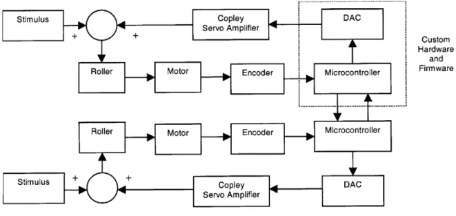
In the interests of saving time, commercially available motor drivers were ultimately used. The 4212Z servo amplifier, made by Copley Controls Corporation, was selected and configured for torque feedback control. This particular amplifier uses locked anti-phase PWM modulation for good near-zero current control and no current dead band. Current is also automatically adjusted through feedback and controlled by an analog voltage. The addition of these amplifiers necessitated slight modifications to the controller board circuitry to accommodate the analog control signals. The modified block diagram in shown in Figure 3.11.
Stimulus Copley DAC
Servo Amplifier + + Custom Hardware and FIIu, | n
]
F 2.- |- . FirmwareFigure 3.11: Modified functional block diagram of inTouch-3 system
Note in the figure that the motor driver block has been replaced by the digital-to-analog converter (DAC) block and the servo amplifier block. The implementation of the DAC block will be described in the next section. The servo amplifiers designated in the figure are the Copley motor drivers. No changes were made to the Copley amplifiers except that the transconductance was changed to 0.7 amperes/volt by replacing one of the configuration resistors. This setting indicates that 0.7 amperes of current are produced for every volt of control signal. The reader is referred to the 4212Z user's manual, available from Copley Controls Corporation, for the details of operation.
The Copley servo amplifiers can be configured to work with motors of varying
inductance. Since the Maxon motors used for the inTouch were on the smaller side, a power inductor was added in series with the motor to increase the total inductance. The addition of the inductor satisfied the servo amplifier's minimum inductance rating and also reduced inductive heating in the motors caused by the locked anti-phase modulation, which might shorten motor operating life.
The unit that is comprised of the DAC, the microcontroller, and the encoder reader, will from this point forward be termed the controller board. This board, along with the Copley servo amplifier will be termed the controller unit.
3.6 Digital-to-Analog Converter
The Copley amplifiers accept industry-standard analog control signals ranging from -10 volts to 10 volts. With the transconductance set at 0.7 amperes/volt as described in the last section, about 1.8 volts are necessary to produce the 1.25 amperes at which the Maxon motors are rated. An external DAC, the Maxim MAX504, was selected to
produce the control voltage. The MAX504 has 10 bits of resolution and is interfaced through serial peripheral interface (SPI).
SPI describes a synchronous serial port. Data is sent to the device from the
microcontoller one bit at a time. Each bit is distinguished by a clock pulse from the microcontroller, hence the term synchronous. The DAC accepts a 10-bit digital value that is transferred by SPI and which sets the analog output voltage. The DAC can be configured to produce a bipolar signal, although this reduces the resolution from 10 bits in one polarity to 9 bits in two. In order to produce bipolar voltages, however, the
DAC must be powered by bipolar voltage supplies. The problem thus became how to convert the five volt logic supply into negative five volts to power the DAC.
The solution was to use a charge pump converter, the Linear Technologies LTC 1044 as shown in Figure 3.12. The charge pump converter works by accumulating charge in a bucket capacitor, C12, then transfering it to a reservoir capacitor, C13. During the first half of the switching cycle, the bucket capacitor is connected to V+, charging it to that voltage. During the second half of the switching cycle, the positive terminal of the
bucket capacitor is connected to ground, while the negative terminal is connected to
VouT, thus inverting the voltage V+.
U5 +5
1 BOOST V+7
3 CAP+ OSC 6 0.l1uF 50V C9
C12 + 4 GND LV 5 \ci
10uF 16V CAP- VOUT +
- 10F16V Cl
Figure 3.12: Charge pump negative voltage converter
With 5 volt and -5 volt supplies, the MAX504 can produce analog voltages in the range of -2.048 to +2.048 volts, over which the 10 bits of resolution are mapped. Thus, by writing the appropriate value into the DAC, the microcontroller can set the drive current to the motor. Feedback is performed in hardware by the servo amplifier to maintain the proper current regardless of the load on the motor.
3.7 Data Communications Interface
The microcontroller communicates with its remote counterpart using the RS-232C standard for serial communication. The RS-232C standard specifies electrical parameters as well as the data format. The most common data format consists of a start bit, a logical HIGH to LOW transition, followed by 8 data bits, followed by a stop bit, a LOW to HIGH transition. This format is known as 8N1, which represents eight data bits, no parity, and one stop bit. The number of data bits can vary from 5 to 9 and more than one stop bit may be used. Another important parameter of RS-232 is the baud rate, which is the number of clock periods per second. InTouch uses 8N1 data format at a baud rate of 19200. Thus, the bit period is approximately 52.08pts and one byte requires 520.8is to be transmitted.
The RS-232C standard uses what is known as non-return-to-zero (NRZ) bipolar voltage signaling. A logical LOW is indicated by a voltage of +5 to + 15 volts, while a logical HIGH is indicated by a voltage of -5 to -15 volts. The driver must be able to operate into loads of 3000 to 7000 ohms with a slew rate less than 30V/ts and with the ability to withstand short circuits. The receiver must present a load of 3000 to 7000 ohms and
convert an input of +3 to +25V to logical LOW and -3 to -25 volts to logical HIGH [8]. An example waveform is shown in the figure below.
any amount of
more than +3V time desired START
"MARKING" LOGIC ONE STOP "MARKING"
less than -3V Dn D, D2 or D7
(LS8) or
parity
Figure 3.13: RS-232 serial byte waveform [8]
The data format is handled by the microcontroller in firmware or internal hardware. The PIC 16C73A contains a module known as a universal synchronous/asynchronous receiver transmitter (USART), which handles generating the baud clock, serializing data for transmission, and shifting incoming data into a receive data register. For
microcontrollers that do not possess internal USART's, an external USART or UART (same as USART but only asynchronous mode) may be used. Alternatively, RS-232 data format may be implemented in firmware. The PIC C compiler from Custom Computer Services, Inc., for instance, includes libraries to facilitate serial communications.
The one disadvantage of software implementations of RS-232 is the processing overhead needed to poll for and receive data, although a method of using interrupts to eliminate the need for polling will be described here. The internal USART of the PIC 16C73A includes associated receive data and transmit data interrupts. The receive data interrupt eliminates the need for data polling. The following interrupt service routine illustrates how to use the interrupt to receive data as it arrives:
#INTRDA
void ServiceRDA() ProcessSerial (getc ());
ProcessSerial () is assumed to be a procedure which processes serial data after it is received. Getc () is a compiler command that copies data from the receive data register into the working register, so that it may be passed as an argument to
ProcessSerial (). In order to activate the receive data interrupt, it must be enabled either by setting the appropriate bit in the PIR1 register of the PIC or by using the compiler's enableinterrupts () function. In addition, the GLOBAL interrupt must be
enabled to activate the interrupt handler. The reader is referred to the PIC 16C73A user's manual available from Microchip Technology and the C compiler manual available from Custom Computer Services for more information.
For microcontrollers that do not possess serial hardware, but do possess the external (EXT) interrupt described in Section 3.4, the following technique may be used. Recall from the discussion above that the RS-232 start bit is a transition from logical high to logical low. Thus to detect the start bit, the EXT interrupt should be configured to trigger on the falling edge and the following interrupt service routine may be used:
#INTEXT
void ServiceEXT()
ProcessSerial (getc ());
In the code segment above, ProcessSerial () is again a procedure to process serial data after it has been received. However, getc () in this case is a compiler-generated software routine that receives RS-232 data. As an implementation note, the INTF bit of the INTCON register should be cleared prior to activating the interrupt handler or there is a possibility that the EXT interrupt service routine may be executed immediately even though no data is being received. Since getc () blocks to receive data, execution will
stop at this point waiting for data that is not present.
The transmit data interrupt is not used in the inTouch application, but indicates when the USART is ready to accept more data to transmit. It is useful in applications where streaming data must be transmitted at the maximum capacity of the channel, since data can be transmitted consecutively with minimal delay between bytes.
To implement RS-232 electrical specifications, a level shifter was used. The Maxim MAX233 provides a convenient minimum-component solution. Charge pumps are traditionally used to produce the bipolar voltage levels of RS-232. The MAX233 conveniently incorporates the entire charge pump internally so that no external capacitors are needed. Although the MAX233 ensures compliance with the RS-232 specifications, it may not be necessary in all applications, especially those in which cost is an issue and where cable lengths are short. The RS-232 standard works for cable lengths of at least 50 feet [8]. The actual limitation is a function of the noise present and the impedance characteristics of the cable and may be maximized by using
the nodes could be separated by large distances. Thus, a fully compliant transceiver such as the MAX233 was needed.
For extended distances, a differential signaling protocol such as RS-485 may be used. In contrast to RS-232 where all signals are referenced to ground, differential signaling protocols use the voltage difference between two lines. This scheme has better noise immunity since noise present in the system will most likely effect both lines (i.e. common mode) and will cancel when the difference is taken (i.e. differential mode). Strictly speaking, RS-485 only defines the electrical parameters. The data format is arbitrary, so RS-232 8N1 data format may be used, for example. The other feature of RS-485 is that it supports multi-drop configurations, so that many nodes may be connected to the same cable, although in this case more complex network arbitration may need to be used. The reader is referred to National Semiconductor application note
1057 for more information about RS-485.
3.8 Power Supply
Most of the power consumed by the inTouch system is in the form of current used to drive the Maxon motors. Under normal interaction patterns, the motors operate only slightly above their no-load current. Maximum current will occur if the users twist the rollers apart in opposite directions until the current limit imposed by the inTouch algorithm takes effect. If all three rollers are subjected to this condition, the approximate power consumption will be (3)(1.25A)(12V) = 45 watts, assuming 100 percent efficiency. In reality, efficiency is less than 100 percent, especially since the efficiency of the Maxon motor is only approximately 80 percent. Moreover, the Copley servo amplifiers require 24 volt supplies to produce 12 volt bidirectional drive.
Inevitably, some loss occurs in the voltage conversion.
Although this may be the maximum continuous current, transient currents produced, for example, when the motor abruptly reverses direction may be much higher. Under these conditions, the power supply must be able to source and sink power rapidly. The power supply must be able to absorb the energy stored in the inductance of the load quickly when a direction reversal, and thus a current reversal, is demanded.
Initial tests used 60 watt power supplies that shut down when large transient currents such as those described above were produced. To solve these problems, a 150 watt
power supply was selected. The rating is arbitrary; 150 watts was selected for reasons of availability and cost.
The electronics, in contrast, operate on five volt supply with low current. A simple method of producing low DC voltages from higher DC voltages is with a linear regulator such as the LM340. The problem with linear regulators is that their efficiency is usually no better than 50 to 60 percent. The resistive loss manifests itself as radiated heat and thus linear regulators must be heat sunk when operating at high power. Recall that power is the product of current and voltage. Thus, high heat dissipation occurs when current is high or voltage is high or both. Recall that the input to the regulator would be 24 volts, assuming that the same power supply for the Copley amplifiers was used for the electronics. This condition would mean that the regulator would need to accommodate a 19 volt voltage drop, so heat dissipation would be enormous even at low currents.
The solution was to implement a switching regulator, which can have an efficiency approaching 90 percent. The National Semiconductor LM2574 is a simple switching regulator that requires a minimum number of external components. The operating principle of the switching regulator is that energy is stored in the magnetic flux of the
inductor and switched into the load. Since flux and not charge, as in the charge pump converter, is used to store energy, the voltage may be higher, lower, or the inverse of the input voltage.
A step-down (buck mode) regulator, as shown below, converts a high voltage to a low voltage. The output voltage is compared to an internal voltage reference. If the output
falls below the reference, an oscillator turns on, which drives current into the inductor until the output voltage rises above the reference. The output capacitor, C5, forms an RLC filter with the inductor and the load to remove the switching frequency, leaving DC voltage. Since the voltage of the inductor is not constrained, the catch diode, D2, turns on when the OUTPUT pin drops to -0.4 volts to protect the regulator. Diode D1 protects the regulator from negative input voltages caused by reversed connections.
![Figure 3.2: Quadrature waveform of encoder [16]](https://thumb-eu.123doks.com/thumbv2/123doknet/14680280.559087/16.918.241.636.299.548/figure-quadrature-waveform-encoder.webp)

![Figure 4.2: System transient response attributes [6]](https://thumb-eu.123doks.com/thumbv2/123doknet/14680280.559087/40.918.228.639.679.906/figure-system-transient-response-attributes.webp)
![Figure 4.4: Gain and phase margins of open-loop transfer function [6]](https://thumb-eu.123doks.com/thumbv2/123doknet/14680280.559087/42.918.278.586.114.574/figure-gain-phase-margins-open-loop-transfer-function.webp)