Design of a Metrology & Characterization System
for a Compliant Mechanisms Course
by Holly B. Laird
SUBMITTED TO THE DEPARTMENT OF MECHANICAL ENGINEERING IN PARTIAL FULFILLMENT OF THE REQUIREMENTS FOR THE DEGREE OF
BACHELOR OF SCIENCE IN MECHANICAL ENGINEERING AT THE
MASSACHUSETTS INSTITUTE OF TECHNOLOGY JUNE 2007
@2007 Holly B. Laird. All rights reserved.
The author hereby grants to MIT permission to reproduce and to distribute publicly paper and electronic copies of this thesis document in whole or in part
in any medium now known or hereafter created.
Signature of Author: Certified by: / Accepted by: John H. Lienhard V MASSACHUSETTS INSTITUTE OF TECHNOLOGY
MAR
0 4 2008
LIBRARIES
Martin L. Culpepper (o w ternational Associate Professor of Mechanical Engineering Thesis Supervisor(
-,
._,. .
Professor of Mechanical Engineering Chairman, Undergraduate Thesis Committee
Design of a Metrology & Characterization System
for a Compliant Mechanisms Course
by Holly B. Laird
Submitted to the Department of Mechanical Engineering on June 11, 2007, in Partial Fulfillment of the Requirements for the Degree of Bachelor of Science in Mechanical
Engineering
Abstract
The purpose of this thesis was to learn about creating an educational kit as a tool for teaching professional engineers in industry about the theory of Freedom and Constraint Topology (FACT), and the new types of flexures that can be designed using this process. The importance of this thesis lies in the benefits compliant mechanisms give to precision engineering. The impact, by improving the quality of designs capable by professional engineers by teaching them about using FACT to design flexures, will contribute to higher quality, more agile, and more reliable technology worldwide. The metrological systems designed for the kit were comprised of a system of sensors and data collection apparati to analyze the physical characteristics of a particular type of flexure known as a "screw flexure", a compliant mechanism that has a single degree of freedom with coupled
translational and rotational motion. Using lead weights of V4 to 2 pounds and two Mitutoyo #ID-S1012E digital Dial Indicators, measurements were taken for the translational and
rotational deflection of the screw flexure. The pitch of the screw flexure was found to be 10.512 in/rad, which was a 9.4% error from the expected value of 11.5 in/rad. The experimental setup was a successful tool for teaching FACT methodology in the specific
case of the screw flexure.
Thesis Supervisor: Martin L. Culpepper
Acknowledgements
First and foremost I would like to thank my thesis advisor Professor Martin L.
Culpepper of the Precision Compliant Systems Laboratory (PCSL) at MIT for providing all of the advice and support that I needed to complete a successful thesis. Professor
Culpepper was an enlightening mentor, and I learned a great deal from his guidance.
I would also like to thank Jonathan Hopkins, a graduate researcher of the PCSL, for all his help in developing this thesis for the dissemination of his research to the engineering world at large. Both he and Professor Culpepper were the most encouraging advisors I could have hoped for, and I could not have done this without them.
A special thank you goes out to Sarah Shivers, my collaborator for this two-person project. Sarah was a joy to work with, and I could not have had a better partner. Finally, I would like to extend my gratitude to the employees of the LMP Machine Shop, and
especially its director, Gerald Wentworth, as well as Grant Elliott, Martin Segado, Karuna Mohindra, Phil Engel, and Louis Fernandes for all their varied and invaluable assistance.
Table of Contents:
Abstract...
2
Acknowledgements ... 3
1
Introduction ...
...
8
1.1 Motivation and Purpose ... 8
1.2 Background ...
0...
...
9
1.3 Theory of Flexures and Constraint-Based Design, and its
Development Into FACT Theory... ... 11
1.4 Theory of Flexures with Single Screw Degree of Freedom... 13
2
Design of Pedagogic Tools for FACT ...
15
2.1
Consumer Requirements ...
15
2.2 Constraints and Functional Requirements ... 16
2.3 Design of Metrology Systems ...
...
17
3
Experimental Setup ...
...
21
3.1
Description of Experimental Apparatus and Procedure
...
21
4
Testing the Apparatus ... 23
4.1 Sample Group Test Plans and Progress ... 23
4.2 Data ... 23
5
Conclusion and Future Work ... 29
5.1
Areas of Imnprovement ...
...
29
5.2 Discussion of Results
...
32
6
References
...
34
List of Figures:
Figure 1: An example of a flexure system with screw motion [2] ... 9
Figure 2: Motion allowed by a single constraint line.
...
11
Figure 3: Freedom and constraint sets as illustrated by Hopkins and
Culpepper [2] ...
13
Figure 4: Topology of constraint and freedom sets of a screw flexure and
its physical geometry and expected motion [2] ... 14
Figure
5:
Screw Flexure to be used in this experimental apparatus... 16
Figure 6: Rotary potentiometer (top and bottom views) used to measure
rotational deflection of the screw flexure...
17
Figure 7: Linear Potentiometer used to measure rotational and
translational deflection of the screw flexure...
18
Figure 8: Dial indicator to measure deflection of the screw flexure... 19
Figure 9: Diagram of geometric measurement techniques for Dial
Indicators ...
20
Figure 10: Photo of full experimental setup ...
21
Figure 11: Graph of force vs. rotation and displacement for fully
Figure 12: Graph of force vs. rotation and displacement for half-way
extended Z component ...
25
Figure 13: Graph of force vs. rotation and displacement for completely
unextended Z component
...
25
Figure 14: Graph of translational deflection vs. rotational deflection for
the case of fully extended Z component
...
26
Figure 15: Graph of translational deflection vs. rotational deflection for
the case of halfway extended Z component
...
27
Figure 16: Graph of translational deflection vs. rotational deflection for
the case of completely unextended Z component
...
27
Figure 17: Solid model of original force gauge designed for experimental
1 Introduction
1.1 Motivation and Purpose
The purpose of this thesis is to learn about the Freedom and Constraint Topology (FACT) method of designing compliant mechanisms, and to design an educational experiment kit as a teaching tool to instruct professional engineers about FACT . The importance of this thesis lies in the benefits compliant mechanisms give to precision
engineering by improving the quality of designs capable in industry. This project's impact, by teaching professional engineers about using FACT to design flexures, will contribute to higher quality, more agile, and more reliable technology worldwide. This paper discusses the design and implementation of a metrological system for the testing of compliant mechanisms in an educational setting.
This experimental kit will be used to teach professional engineers about (1) the principles of precision flexure design and (2) the behavior of non-conventional compliant mechanisms that move with complex motions. The flexure to be analyzed is a flexure moves with a coupled rotation and translational motion with the application of a single force. This flexure is referred to as a "screw flexure" in this paper. An example of such a flexure may be seen in Figure 1. Due to the geometry of this flexure, when the bottom disk is grounded and a force is applied to the top, the upper disk will rotate counter-clockwise and translate downward.
Figure 1: An example of a flexure system with screw motion [2].
1.2 Background
Compliant mechanisms are an important part of precision engineering. They are used to make machines work more reliably, and thus enable specificity in mechanical design as low as the nanoscale. The flexure system to be analyzed in this educational kit, the screw flexure, has been previously unexploited in industrial design. Due to the complex motion the screw flexure undergoes, they were extremely difficult to design since there was no systematic methodology of doing so; engineers were required to intuitively guess. Recently the Precision Compliant Systems Laboratory (PCSL) at MIT developed a new mathematical method of designing and analyzing flexures known as Freedom and
Constraint Topology (FACT). The theory of FACT enables a methodical step-by-step technique of desigining flexures based on only the degrees of freedom or the degrees of constraint required. Every type of screw motion physically possible has been determined using FACT, making the design of screw motion flexures easier and possible for even novice designers. Now the PCSL hopes to disseminate their methodology out amongst the professional engineering community. One purpose of this project is to learn how to teach these methods in compliant mechanism design to professional engineers who have been in the workforce for many years. They are unique in that many of them tend to engineer based more on intuition and experience than mathematical rules.
Engineering is a hands-on discipline and professional engineers that have been in the workforce for decades are sometimes out of practice with university-style lectures on engineering theory. Their thinking lies mostly in the physical realm, and may become easily frustrated with abstract concepts and models when they are not combined with physical examples/experiments. The disparity in methods of understanding between engineering researchers and professional engineers creates a barrier for disseminating information. This project will aim to bridge this learning gap between the university engineers and the industry engineers, so that the knowledge may be disseminated amongst the two by taking the theory and models developed by the PCSL and teaching them. The metrological systems of this experimental kit will enable the engineers to link the
mathematical concepts to they physical models. This will build their confidence and understanding of the abstract mathematical models, enabling the engineers to develop their innate ability to design their own flexures with similarly complex motion.
1.3 Theory of Flexures and Constraint-Based Design, and its
Development Into FACT Theory
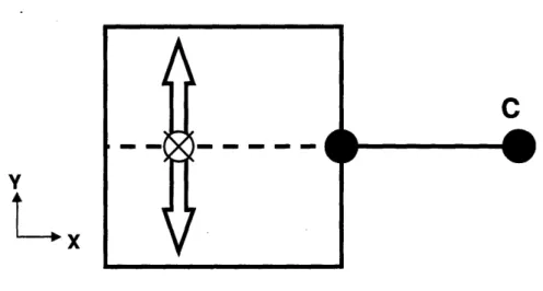
Constraints on a body may be modeled as a single line. Constraints govern the movement of rigid bodies. They allow the points that are inside the object and along the constraint line to only move perpendicular to the constraint line. Those points cannot move along the constraint line [1]. A two-dimensional representation of this concept is shown in Figure 2. The line labeled "C" is the constraint line, and the white arrows show the
directions in which this body is allowed to move.
- - -
-4
C
Vr
Figure 2: Motion allowed by a single constraint line.
If multiple constraints are placed on the same plane of a certain body, their intersection point marks the instant center of rotation about which the body has a rotational degree of freedom. When two lines are parallel, they intersect at infinity. An instant center of
L
Y
rotation at infinity forces a body to move in an arc of infinite radius. The body's motion therefore emulates pure translational motion for small movements.
When constraints are non-redundant, the addition of each one represents the loss of a degree of freedom. There are six degrees of freedom (DOFs) in a three-dimensional body: pure translation along the x, y and z axes, and pure rotation about each of these axes. Equation 1 can determine the DOFs in any given body:
R=6-C (1)
Where R is the number of independent DOFs and C is the number of non-redundant constraints [2].
The Rule of Complimentary Patterns, originated by Blanding [1] states that every freedom line intersects every constraint line. This rule was further refined by Hopkins and Culpepper [2] as the basis for the FACT methodology. Hopkins and Culpepper used constraint sets and freedom sets instead of lines; the standard geometry of which are shown in Figure 3. Each constraint or freedom set contains a geometry filled with redundancies. Any line will be equivalent to another line in that set, and thus will not add an independent degree of freedom or constraint. In this classification, freedom sets shown as such
represent translational motion with hoops, and rotational motion with lines. A body will translate along the axis of a hoop, and will rotate along the axis of a line.
Figure 3: Freedom and constraint sets as illustrated by Hopkins and Culpepper [2].
1.4 Theory of Flexures with Single Screw Degree of Freedom
In screw flexure systems, the constraint lines and freedom lines do not intersect, but the freedom sets are obtained by finding whatever degrees of freedom are complimentary to all constraint sets. The flexure used in this project and its freedom and constraint topology are illustrated in Figure 4. There is only one degree of freedom, a coupled pitch of rotational and translational motion that goes through the center of the upper stage.
Applying a force to this flexure system will cause it to deflect as shown in the bottom right section of Figure 4. (4) ()
-~1·l~lp
Z -C DFigure 4: Topology of constraint and freedom sets of a screw flexure and its physical geometry and expected motion [2].
A more detailed mathematical foundation for screw theory and the mathematics behidn flexures with a single screw degree of freedom may be found in the Hopkins and Culpepper paper on FACT [2].
I
4
1-ý
2 Design of Pedagogic Tools for FACT
2.1 Consumer Requirements
This section describes the conditions which the design of the experimental mechanisms were obligated to fulfill. The metrological systems for this project were designed to work in conjunction with the screw flexure designed and constructed by Sarah Shivers. In order
to prove a useful educational tool, the experimental apparatus must (1) subject the screw flexure to a variety of loads ranging from one pound to five pounds, (2) measure the
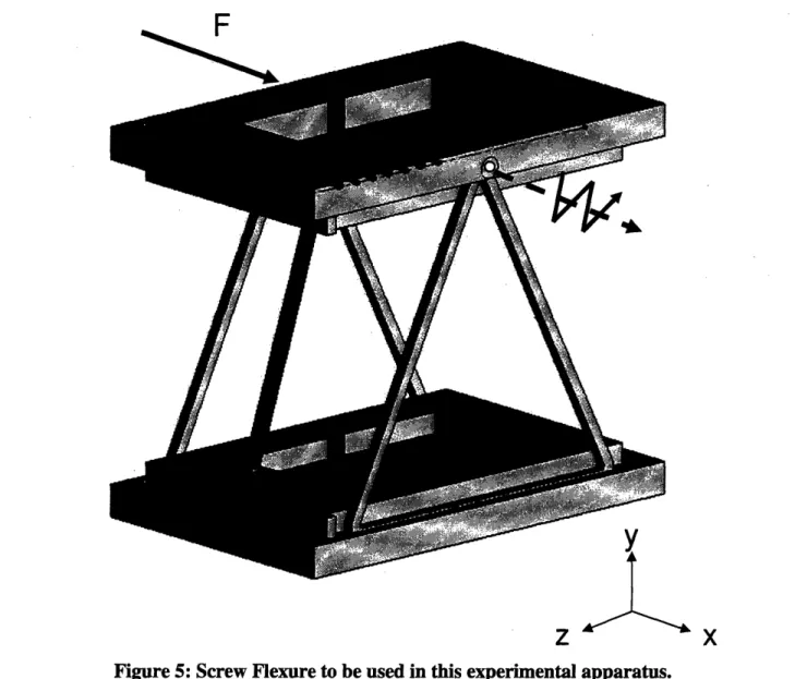
translational and rotational motions of the screw flexure under those loads, and (3) be able to be disassembled for portability. A solid model of the screw flexure to be used in this project is shown in Figure 5.
This screw flexure's behavior is such that when a force is applied to the upper stage at the specified point, it will translate in the positive x direction, and it will rotate in the positive Ox direction, thus causing the closer edge of the upper stage to move down in the negative y direction. The rotational axis goes through the center of the upper stage, and is drawn in Figure 5.
_
F
L A Figure 5: Screw Flexure to be used in this experimental apparatus.
2.2 Constraints and Functional Requirements
The screw flexure was meant to be designed to have translational deflections on the order of about one inch and rotational deflections of about twenty degrees for
approximately four pounds of applied force. The sensors and data collection apparati must have resolutions on an order of at least 10 times more sensitive than the limits listed above in order to be able to detect meaningful trends.
Design changes in the screw flexure's materials and dimensions caused it to have much smaller deflections once manufactured. When applying the requisite four pounds of force, the stage would only translate about 0.02" and rotate about one degree. This decrease in range of mobility caused difficulties in the metrological design which are described below.
2.3 Design of Metrology Systems
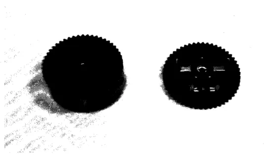
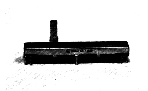
The first set of sensors used to capture the rotational and translational motion of the screw flexure was a set of potentiometers, one rotary and one linear slide. The linear slide potentiometer was Panasonic model #EWA-P1OC15A14, and the rotary was Panasonic model #EVL-HFAAO5A24. They are shown below in Figures 6 and 7.
Figure 6: Rotary potentiometer (top and bottom views) used to measure rotational deflection of the screw flexure
i i
:: ~
Figure 7: Linear Potentiometer used to measure rotational and translational deflection of the screw flexure
Measuring with the potentiometers was difficult. The linear potentiometer, because it was designed for use in audio systems, had a logarithmic output. Without the
potentiometer's governing equation, the equivalent linear motion of the flexure could not be determined. The rotary potentiometer experienced problems in its coupling system. The linkage was comprised of two interlocking plastic pieces. The two linkages were affixed to the rotary potentiometer and the screw flexure. These interlocking pieces were manufactured on the waterjet, causing enough error such that the potentiometer was unable to detect the small angular deflections that the screw flexure underwent. When the screw flexure was redesigned, its stiffness increased enough to render the potentiometer's sensitivity insufficient.
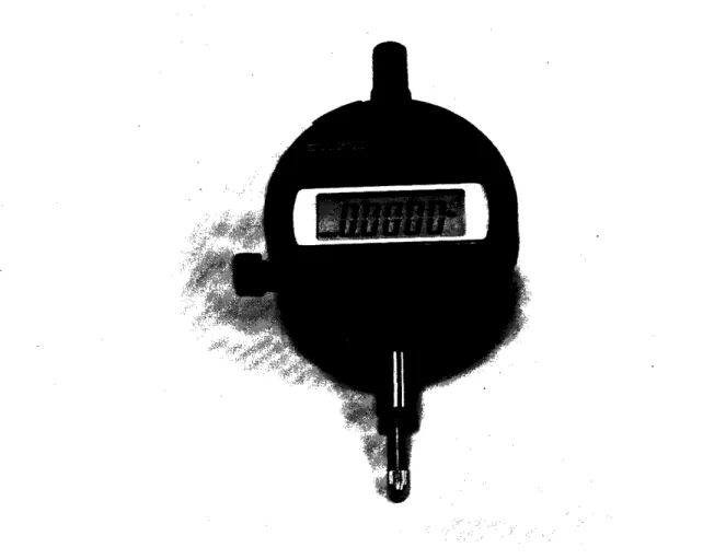
The solution to the heightened sensitivity requirements was to use digital dial indicators, Mitutoyo model #ID-S1012E, shown in Figure 8. With resolution of 0.0005 inches, they were adequate for the needs of the redesigned screw flexure.
Figure 8: Dial indicator to measure deflection of the screw flexure
Two separate dial indicators were used in the measurement of both rotational and translational displacement of the screw flexure. The one used for translational
displacement was lined up to the edge of the upper stage, and measured the deflection that way. The second dial indicator was situated on the far edge of the screw flexure's side, such that when the flexure rotated, the upper stage would compress the plunger of the dial indicator. Figure 9 shows arrows indicating the locations in which the deflections were
measured. The second dial indicator measured the vertical translation due to the rotation of the upper stage.
Figure 9: Diagram of geometric measurement techniques for Dial Indicators
Where d is the variable distance between the axis of rotation and the location of the side Z constraint piece, y is the vertical distance the edge of the stage moved, 0 is the angle about which it rotated, and x is the horizontal distance the stage moved forward.
The angle of rotational displacement 0, was found by taking the inverse sine of the quotient of the vertical displacement over the arm length between the axis of rotation and the edge piece of the flexure as in Equation 2.
S=
sinm-
(2)
The distance d, illustrated in Figure 9, was variable depending on where the sliding side constraint was positioned.
3 Experimental Setup
3.1 Description of Experimental Apparatus and Procedure
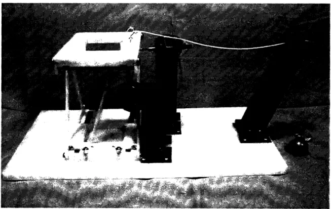
The experimental apparatus consisted of the screw flexure and the two dial indicators fastened to a baseboard with the necessary support structures. To apply force to the screw flexure, lead weights of sizes /4pound to 2 pounds were hung in various combinations from a string that was tied to a hook connecting to the screw flexure. The entire system is shown in Figure 10.
To test the characteristics of the screw flexure, the weights were hung from the connecting string in increments of 1/4 or ½2 pounds, from zero to four pounds, and in the case with the fully extended side Z constraint piece, zero to five pounds. The resulting translational and rotational deflections were recorded from the dial indicators. Up to three separate measurements were taken for each weight level.
This process was completed three times with different values of d, the distance between the rotational axis and the position of the side constraint piece. The screw flexure was designed to be adjustable such that different pitches could be obtained by varying d. Equation 3 describes how to find the ideal pitch of each setting.
Pidea = d tan 0 (3)
Where p is the pitch, and + is the included angle of the Z-shaped side constraint piece. For this design, tan(ý)=3, and d had values of 3.5 inches for fully extended, 2 inches for half-way extended, and 0.125 inches for at the central position. Therefore the expected pitches were 0.375, 6, and 11.5 inches per radian.
The measured pitch was found by dividing the linear displacement by the rotational displacement as shown by Equation 4.
Pexp = (4)
Where 0 is measured in radians so that the units [in/rad] are equivalent to those in Equation
4 Testing the Apparatus
4.1 Sample Group Test Plans and Progress
A sample group was invited to test the experiment in order to ascertain the success of the design, and to determine what improvements might be made to improve educational value of the kit. Two volunteers came, listened to a short presentation on the theory and principles of FACT, and performed the experiment. Before and after the tests were performed, the two subjects were encouraged to play with the screw flexure to develop a better understanding of its physical characteristics and its motion.
The volunteers were solicited based on the qualifications of (1) educational background in mechanical engineering for at least two years, (2) knowledge of basic kinematics and beam bending, and (3) understanding of general principles of flexures, and their constraints and degrees of freedom. This enabled the volunteers to begin the experiment with an understanding of Constraint Based Design equal to the professional engineers in general.
During this test the potentiometers were used to obtain displacement values. Therefore the data collection portion of the experiment suffered, and was of little value to the
volunteers' experience. The experiment was successful in qualitatitvely demonstrating the concepts that had been discussed in the presentation.
4.2 Data
The first test of the experimental apparatus was unsuccessful at obtaining viable data. The second test employed the dial indicators to measure displacement and achieved
worthwhile results. Measurements of linear displacement and rotational displacement were taken for three separate cases: (1) when the side Z constraint piece was positioned at its
fully extended location, 3.5" away from the center axis, (2) when the side Z constraint piece was at its half-way extended location, 2.5" away from the center axis, and (3) when
the side Z constraint piece was in its completely unextended position, 0.125" away from the central axis. The following Figures 11, 12 and 13 show the data obtained from the second test. They show the linear deflection and rotational deflection vs. the weight applied to the screw flexure.
.0 4-a0 ·rl týi (U .5 4m..)_.O 0 *14 .5 Od) 4oa4-a 0I
Weight Applied [lb]
0.15
0.05
I I
00o
Linear Deflection
ooo Rotational Deflection
[
B.
I
B
-
I
10
0 A V 4Weight Applied [lb]
Figure 12: Graph of force vs. rotation and displacement for half-way extended Z component 0.1 0.05 1 0 O 0 .5 0
Weight Applied [lb]
Figure 13: Graph of force vs. rotation and displacement for completely unextended Z component 0 o C. a5) .5 O d
ooo Linear Deflection
/
ooo Rotational Deflectioni
0
S I , I M a 5 · · • n I. O, R iAll three plots show the linearity of deflection vs. applied weight in both the rotational and translational cases. For loading of four pounds, the screw flexure linearly translated 0.176" in case where the side constraint piece was fully extended to 3.5" away from the center axis. In the halfway extended case when the side piece 2" away from the center axis the flexure translated 0.169", and in the unextended case when the side piece was 0.125" away from the center axis, the screw flexure translated 0.107". The screw flexure also
rotated 0.960, 1.020, and 0.520 in the fully extended, halfway extended, and unextended
cases, respectively. 0.25
. 0.20
0o 0 ® 0.150o
. 0.10 I' 0.05 I-0 I-0I-00v.v 0.00 0.01 0.01 0.02Rotational Deflection [rad]
0.02 0.03
Figure 14: Graph of translational deflection vs. rotational deflection for the case of fully extended Z component o..4 4. oIP °•"+ nI n lJn P
0.01 0.01
Rotational Deflection [rad]
0.02 0.02
Graph of translational deflection vs. rotational deflection for the case of halfway extended Z component
0.00 0.00 0.01 0.01 0.01
Rotational Deflection [rad]
Figure 16: Graph of translational deflection vs. rotational deflection for the case of completely unextended Z component
- ' 0.18 0.16 0.14 0.12 -0.10 0.08 0.06 0.04 -0.02 -0.00 Figure 15: 0.12 0.10 0.08 -0.06 0.04 0.02 -0no_ -4. *' 4.· *4. 0.00 -· · · · I I u.0u -. .
-Figures 14, 15 and 16 show plots of the translational deflection vs. the rotational
deflection for each of the three cases. The slope of the linear fit line gives the experimental value of the pitch obtained from the measured data. The pitch found for each of the three cases was determined to be 10.51, 8.19, and 8.90 inches per radian for the fully extended, halfway extended, and unextended cases, respectively. The predicted values for pitch based on the dimensions of the screw flexure were calculated based on Equation 3 to be
11.5, 6, and 0.375 in/rad for the fully extended, halfway extended, and unextended cases, respectively, for a percent difference of 9.4%, 31.9%, and 95.8%.
4.3 Discussion
Only the measured pitch for the case with the fully extended side Z constraint was within 10% of its predicted value. The halfway extended case showed just over a 30% error, but was still on the same order of magnitude. The unextended case exhibited a pitch that was one order of magnitude different from the predicted value. The theory behind the
screw flexure states that there should be virtually no rotation when the side constraint is situated at the center, and that the screw flexure should demonstrate pure translational motion only.
The main reason why the flexure may be suspected to not exhibit the characteristics of an ideal screw flexure model is that it is not a perfectly rigid body and it is not an ideal situation. This flexure will not be kept perfectly rigid within the degrees of constraint in which it is not supposed to move. This lack in perfect rigidity is because the components are not ideal constraints. They behave similarly to the ideal constraint of the line and body
expected in the demonstration. FACT is a mathematical model for infinitesimally small motions and infinitely rigid constraints. Even the strongest materials and the tightest constraints are never infinitely rigid in any direction.
Another source of error was that the piece that held the side Z constraint into the entire flexure was held in place by nothing more than magnets. The magnets could have been able to hold it together, but some of them had fallen out in previous tests because they were too strong to permanently affix inside the flexure and would frequently pop out and jam the sliding mechanism. To mitigate this problem, the base piece of the side Z constraint piece was held down physically during the tests, but it may be suspected that the forces of up to four pounds were still too much for it to stay down, thus adding rotational error.
5
Conclusion and Future Work
5.1 Areas of Improvement
The potentiometers, as described before, were the main source of technical difficulty in this project. The linear potentiometer was functional at taking measurements, but the data was made useless by the fact that it had been measured logarithmically and could not be reinterpreted to show the linear deflection. The governing equation was unavailable in the manufacturer's specifications, undoubtedly because as an audio potentiometer, this
component was only every planned to be used to obtain logarithmic outputs, and therefore such information is unnecessary to the average consumer. In the future it would be beneficial to find a potentiometer of the same shape and dimensions that does not have a logarithmic output.
The rotary potentiometer presented a more uncompromising difficulty. Without a coupling system that could transmit the rotational deflection of the screw flexure to the rotary potentiometer without error greater than 0.0050, the system fail to give effective data. Such a system would require manufacturing precision and design that was unobtainable with the resources available to this project at this time.
The problem with the rotary potentiometer could be significantly diminished by changing the design of the screw flexure. By choosing materials and dimensions based on a desire for flexibility, the range of motion under expected applied loads of about four pounds could be increased to include rotational motion upwards of 20-250, obviating the need for precision in angular displacement lower than 0.50 maximum.
An force gauge was designed to be incorporated into this experimental setup as the original sensor for determining the load applied to the flexure. It was comprised of two thin beams housed in a larger structure and connected together at the force application point. Each thin beam was to have a strain gauge attached, coupled to an amplifying circuit which would then be fed into an analog to digital converter along with the potentiometer signals. The solid model of the force gauge is shown in Figure 17.
Due to difficulty with the electronics, the force gauge was never fully completed and calibrated. The system described previously in the experimental procedure of attaching weights to a pulley system was then used as the primary load-applying system. Due to the precision in loads that could be achieved with the weight and pulley system, it was
determined to be sufficient for the purpose of the experiment and the force gauge was set aside. For the benefit of those using this experimental apparatus to learn about screw flexures, the force gauge would only provide worthwhile data if it could be coupled with
functional electronic sensors to create graphs on a computer. Applying the forces by hand with the force gauge and trying to read the deflections off of the dial indicators would not be a straightforward enough system for taking measurements and would only lead to poor data and frustration.
Figure 17: Solid model of original force gauge designed for experimental setup
The dial indicators took extremely precise measurements and were more than
sufficiently able to compensate for the miniscule motions of the screw flexure. The only difficulty that arose with them is the need to take data down by hand for each individual point.
The only difficulties for the volunteer test subjects during the experimental were those closely coupled with the technical difficulties. During the sample group test, the electronic sensors failed to give meaningful data to the volunteer subjects, and they ended up
scrapping the experimental procedure in place of simply playing with the flexure and its motion by hand.
Recording data from the dial indicators proved tedious and time-consuming. For the purposes of testing and documentation, a larger amount of data points were taken than would be required when using this experimental apparatus for educating engineers.
Writing the numbers down would be an inconvenience, but it would not be such a time sink when taking roughly 10 points as opposed to 30-60. Nonetheless, it would be worthwhile to consider developing the other system of measurement for the final version of this
experimental apparatus in order to enhance the overall experience of learning from this kit. If the difficulties with the electronics systems could be minimized by selecting better potentiometers and increasing the flexibility of the screw flexure, such a system would be the most desirable.
The volunteer subjects found the experimental apparatus fascinating and very useful for visualizing the screw theory of FACT, despite the technical difficulties which prevented them from obtaining useful data.
5.2
Discussion of Results
With the side Z constraint fully extended to the farthest point it can travel from the central axis, the screw flexure exhibited the expected physical behavior and demonstrated a pitch of 10.512 inches per radian. This value falls within 10% of the expected pitch of 11.5 in/rad calculated theoretically. The halfway extended and unextended cases demonstrated pitches of 8.185 and 8.898 in/rad, which differed 30.2% and 95.7% from the predicted
Improvements could be made to the data acquisition systems, by developing a functional set of electronic components that could interface with a computer in order to capture the measurements on a spreadsheet for easy analysis. This would be easier to do with a screw flexure that was redesigned to be more flexible to exhibit wider ranges of motion, on the order of about an inch of linear displacement and 20 degrees of rotational displacement when applied with about four pounds of force.
The numbers show that this experimental apparatus is able to demonstrate some of the most important concepts of screw theory from the Freedom and Constraint Topology models. The data and the input from test subjects has confirmed that this experimental apparatus is an informative teaching tool for educating students and professional engineers about the theory and physical properties of screw flexures. Using this experimental kit to teach professional engineers about screw flexures would facilitate the understanding of the concepts and theory behind screw flexures and FACT methodology.
6 References
[1] D. Blanding. Exact Constraint: Machine Design Using Kinematic Principles. ASME
Press, 1999.
[2] J. Hopkins, and M. Culpepper. "Synthesis of Multi-degree of Freedom Flexure System Concepts via Freedom and Constraint Topologies (FACT)", 2007.
[3] L. Hale. "Exact-Constraint Design" Chapter 2.6 in "Principles and Techniques for Designing Precision Machines", pp. 67-81.
7 Appendices
This section contains the complete data tables for all measurements taken of the screw flexure during experimentation and data collection done with the dial indicators. Table 1 contains the measurements from the first condition, where the side Z constraint piece was fully extended. Table 2 contains the measurements from the second condition, where the side Z constraint piece was halfway extended, and Table 3 contains the measurements from the third condition, where the side Z constraint piece was completely unextended.
Table 1: Measurements from the first condition, where the side Z constraint piece was fully extended. Y Position X Position [in] [in] 0.0385 0.0380 0.0375 0.0425 0.0410 0.0410 0.0455 0.0455 0.0455 0.0505 0.0505 0.0505 0.0555 0.0560 0.0555 0.0605 0.0600 0.0590 0.0610 0.0610 0.0605 0.0675 0.0675 0.0670 0.0720 0.0720 0.0705 0.0770 0.0785 0.0770 0.0120 0.0110 0.0110 0.0180 0.0155 0.0155 0.0230 0.0230 0.0230 0.0315 0.0310 0.0320 0.0450 0.0455 0.0445 0.0570 0.0565 0.0550 0.0680 0.0660 0.0655 0.0815 0.0815 0.0805 0.0945 0.0935 0.0925 0.1065 0.1060 0.1055 Y Deflection [in] 0.0005 0.0000 -0.0005 0.0045 0.0030 0.0030 0.0075 0.0075 0.0075 0.0125 0.0125 0.0125 0.0175 0.0180 0.0175 0.0225 0.0220 0.0210 0.0230 0.0230 0.0225 0.0295 0.0295 0.0290 0.0340 0.0340 0.0325 0.0390 0.0405 0.0390 X Deflection [in] 0.0007 -0.0003 -0.0003 0.0067 0.0042 0.0042 0.0117 0.0117 0.0117 0.0202 0.0197 0.0207 0.0337 0.0342 0.0332 0.0457 0.0452 0.0437 0.0567 0.0547 0.0542 0.0702 0.0702 0.0692 0.0832 0.0822 0.0812 0.0952 0.0947 0.0942 Table 1 (Continued) Weight [Ibs] 0.00 0.00 0.00 0.25 0.25 0.25 0.50 0.50 0.50 0.75 0.75 0.75 1.00 1.00 1.00 1.25 1.25 1.25 1.50 1.50 1.50 1.75 1.75 1.75 2.00 2.00 2.00 2.25 2.25 2.25 Rotational Def. [rad] 0.0001 0.0000 -0.0001 0.0010 0.0007 0.0007 0.0017 0.0017 0.0017 0.0029 0.0029 0.0029 0.0040 0.0041 0.0040 0.0051 0.0050 0.0048 0.0053 0.0053 0.0051 0.0067 0.0067 0.0066 0.0078 0.0078 0.0074 0.0089 0.0093 0.0089 Rotational Def. [deg] 0.0033 0.0000 -0.0033 0.0295 0.0196 0.0196 0.0491 0.0491 0.0491 0.0819 0.0819 0.0819 0.1146 0.1179 0.1146 0.1473 0.1441 0.1375 0.1506 0.1506 0.1473 0.1932 0.1932 0.1899 0.2226 0.2226 0.2128 0.2554 0.2652 0.2554
Y Position X Position [in] [in] Weight [Ibs] 2.50 2.50 2.50 2.75 2.75 2.75 3.00 3.00 3.00 3.25 3.25 3.25 3.50 3.50 3.50 3.75 3.75 3.75 4.00 4.00 4.00 4.25 4.25 4.25 4.50 4.50 4.50 4.75 4.75 4.75 5.00 5.00 5.00 0.0820 0.0810 0.0805 0.0850 0.0860 0.0875 0.0915 0.0925 0.0920 0.0965 0.0970 0.0965 0.1000 0.1020 0.1030 0.1035 0.1060 0.1055 0.1105 0.1110 0.1115 0.1155 0.1165 0.1150 0.1190 0.1220 0.1200 0.1240 0.1210 0.1205 0.1305 0.1300 0.1315 0.1175 0.1165 0.1150 0.1220 0.1225 0.1230 0.1360 0.1370 0.1365 0.1490 0.1500 0.1480 0.1600 0.1620 0.1630 0.1805 0.1710 0.1720 0.1880 0.1855 0.1895 0.1990 0.2000 0.1995 0.2105 0.2150 0.2100 0.2220 0.2270 0.2280 0.2305 0.2300 0.2335 Y Deflection [in] 0.0440 0.0430 0.0425 0.0470 0.0480 0.0495 0.0535 0.0545 0.0540 0.0585 0.0590 0.0585 0.0620 0.0640 0.0650 0.0655 0.0680 0.0675 0.0725 0.0730 0.0735 0.0775 0.0785 0.0770 0.0810 0.0840 0.0820 0.0860 0.0830 0.0825 0.0925 0.0920 0.0935 X Deflection [in] 0.1062 0.1052 0.1037 0.1107 0.1112 0.1117 0.1247 0.1257 0.1252 0.1377 0.1387 0.1367 0.1487 0.1507 0.1517 0.1692 0.1597 0.1607 0.1767 0.1742 0.1782 0.1877 0.1887 0.1882 0.1992 0.2037 0.1987 0.2107 0.2157 0.2167 0.2192 0.2187 0.2222 Rotational Def. [rad] 0.0101 0.0098 0.0097 0.0107 0.0110 0.0113 0.0122 0.0125 0.0123 0.0134 0.0135 0.0134 0.0142 0.0146 0.0149 0.0150 0.0155 0.0154 0.0166 0.0167 0.0168 0.0177 0.0179 0.0176 0.0185 0.0192 0.0187 0.0197 0.0190 0.0189 0.0211 0.0210 0.0214 Rotational Def. [deg] 0.2881 0.2816 0.2783 0.3078 0.3143 0.3241 0.3503 0.3569 0.3536 0.3831 0.3863 0.3831 0.4060 0.4191 0.4256 0.4289 0.4453 0.4420 0.4748 0.4780 0.4813 0.5075 0.5141 0.5042 0.5304 0.5501 0.5370 0.5632 0.5435 0.5402 0.6057 0.6025 0.6123
Table 2: Measurements from the second condition, where the side Z constraint piece was halfway extended.
Y Position X Position Y Deflection
[in] [in] [in]
Weight [Ibs] 0.00 0.00 0.25 0.25 0.25 0.50 0.50 0.50 1.00 1.00 1.00 1.50 1.50 1.50 2.00 2.00 2.00 2.50 2.50 2.50 3.00 3.00
3.00
3.50 3.50 3.50 4.00 4.00 0.0245 0.0240 0.0300 0.0300 0.0290 0.0335 0.0320 0.0335 0.0435 0.0440 0.0445 0.0535 0.0540 0.0545 0.0660 0.0655 0.0650 0.0750 0.0775 0.0770 0.0890 0.0880 0.0870 0.0990 0.0955 0.0945 0.1030 0.1020 0.0010 0.0010 0.0070 0.0090 0.0075 0.0120 0.0125 0.0140 0.0275 0.0305 0.0315 0.0465 0.0480 0.0490 0.0730 0.0705 0.0705 0.0885 0.0900 0.0925 0.1130 0.1165 0.1095 0.1295 0.1345 0.1385 0.1715 0.1710 0.0003 -0.0003 0.0058 0.0058 0.0048 0.0093 0.0078 0.0093 0.0193 0.0198 0.0203 0.0293 0.0298 0.0303 0.0418 0.0413 0.0408 0.0508 0.0533 0.0528 0.0648 0.0638 0.0628 0.0748 0.0713 0.0703 0.0788 0.0778 X Deflection [in] 0.0000 0.0000 0.0060 0.0080 0.0065 0.0110 0.0115 0.0130 0.0265 0.0295 0.0305 0.0455 0.0470 0.0480 0.0720 0.0695 0.0695 0.0875 0.0890 0.0915 0.1120 0.1155 0.1085 0.1285 0.1335 0.1375 0.1705 0.1700 Rotational Def. [rad] 0.0001 -0.0001 0.0013 0.0013 0.0011 0.0021 0.0018 0.0021 0.0044 0.0045 0.0046 0.0067 0.0068 0.0069 0.0095 0.0094 0.0093 0.0116 0.0122 0.0121 0.0148 0.0146 0.0143 0.0171 0.0163 0.0161 0.0180 0.0178 Rotational Def. [deg] 0.0016 -0.0016 0.0377 0.0377 0.0311 0.0606 0.0507 0.0606 0.1261 0.1293 0.1326 0.1915 0.1948 0.1981 0.2734 0.2701 0.2668 0.3323 0.3487 0.3454 0.4240 0.4175 0.4109 0.4895 0.4666 0.4600 0.5157 0.5091Table 3: Measurements from the third condition, where the side Z constraint piece was completely unextended. Weight [Ibs] 0.00 0.25 0.25 0.25 0.50 0.50 0.50 1.00 1.00 1.00 1.50 1.50 1.50 2.00 2.00 2.00 2.50 2.50 2.50 3.00 3.00 3.00 3.50 3.50 3.50 4.00 4.00 4.00 X Deflection Y Position [in] 0.0300 0.0335 0.0325 0.0320 0.0345 0.0350 0.0345 0.0405 0.0410 0.0420 0.0455 0.0465 0.0455 0.0535 0.0530 0.0540 0.0585 0.0570 0.0575 0.0620 0.0620 0.0635 0.0660 0.0655 0.0655 0.0685 0.0690 0.0710 X Position [in] 0.0500 0.0520 0.0510 0.0510 0.0540 0.0545 0.0550 0.0615 0.0630 0.0640 0.0710 0.0715 0.0715 0.0645 0.0635 0.0865 0.1015 0.0995 0.1005 0.1110 0.1115 0.1130 0.1295 0.1280 0.1270 0.1580 0.1550 0.1565 Y Deflection [in] 0.0000 0.0035 0.0025 0.0020 0.0045 0.0050 0.0045 0.0105 0.0110 0.0120 0.0155 0.0165 0.0155 0.0235 0.0230 0.0240 0.0285 0.0270 0.0275 0.0320 0.0320 0.0335 0.0360 0.0355 0.0355 0.0385 0.0390 0.0410 0.0000 0.0020 0.0010 0.0010 0.0040 0.0045 0.0050 0.0115 0.0130 0.0140 0.0210 0.0215 0.0215 0.0145 0.0135 0.0365 0.0515 0.0495 0.0505 0.0610 0.0615 0.0630 0.0795 0.0780 0.0770 0.1080 0.1050 0.1065 Rotational Def. [rad] 0.0000 0.0008 0.0006 0.0005 0.0010 0.0011 0.0010 0.0024 0.0025 0.0027 0.0035 0.0038 0.0035 0.0054 0.0053 0.0055 0.0065 0.0062 0.0063 0.0073 0.0073 0.0077 0.0082 0.0081 0.0081 0.0088 0.0089 0.0094 Rotational Def. [deg] 0.0000 0.0229 0.0164 0.0131 0.0295 0.0327 0.0295 0.0688 0.0720 0.0786 0.1015 0.1080 0.1015 0.1539 0.1506 0.1572 0.1866 0.1768 0.1801 0.2095 0.2095 0.2194 0.2357 0.2325 0.2325 0.2521 0.2554 0.2685
![Figure 1: An example of a flexure system with screw motion [2].](https://thumb-eu.123doks.com/thumbv2/123doknet/14684993.560010/9.918.156.703.111.604/figure-example-flexure-screw-motion.webp)
![Figure 3: Freedom and constraint sets as illustrated by Hopkins and Culpepper [2].](https://thumb-eu.123doks.com/thumbv2/123doknet/14684993.560010/13.918.229.703.90.655/figure-freedom-constraint-sets-illustrated-hopkins-culpepper.webp)
![Figure 4: Topology of constraint and freedom sets of a screw flexure and its physical geometry and expected motion [2].](https://thumb-eu.123doks.com/thumbv2/123doknet/14684993.560010/14.918.117.793.218.708/figure-topology-constraint-freedom-flexure-physical-geometry-expected.webp)