Design of a Four-Point Seat-Belt Presenter
byMiguel Angel Chavez
Submitted to the Department of Mechanical Engineering in partial fulfillment of the requirements for the degree of
Bachelor of Science in Mechanical Engineering
at the
MASSACHUSETTS INSTITUTE OF TECHNOLOGY
_ May 2001
(© Massachusetts Institute of Technology 2001. All rights reserved.
Signature of Author ...
. r -... . ....'!Wpartmente chaic
hgxneering
May 11, 2001
.n
Certified by ... .... ... ... , c. W... .-
c____2Z___-.i~esto E. Blanco
Adjunct Professor of Mechanical Engin eering
Thesis Supervisor
Accepted by ...
....
I . ... . ...Professor Ernest G. Cravalho
Chairman of the Undergraduate Thesis Committee
MCI4WES,
JIN. 2 8 001
LIBRARIES I __ .. _I .. ,.~_I ... *L
Design of a Four-Point Seat-Belt Presenter
byMiguel Angel Chavez
Submitted to the Department of Mechanical Engineering in partial fulfillment of the requirements for the degree of
Bachelor of Science in Mechanical Engineering
Abstract
The ambition of this thesis was to design and prototype a seat-belt presenter of a four-point seat-belt system for the Lear Corporation. The seat-belt presenter designed is to be implemented in automobile seats in order to facilitate putting a four-point seat belt. The worked perform is the culmination of both Petr Petri and myself in our efforts to find a method to properly present a four-point seat-belt system. The design utilizes a magnet at the end of an aluminum arm that is pivoted below a person's knee on the seat. A sensor detects when a person sits down and begins a series of actions to present the seat belt. The device uses a set of four mechanical sensors to locate the position of the arm, the seat belt, and on the seat to detect when a person sits down. A control system, which utilizes logic components, then decides what direction to turn the ann in and when to stop it. The prototype that was built to simulate the seat-belt presenter appears to work well but has little details that need to worked up before a product like this enters the market. Among the most important issues to be resolved is the prototyping of the second arm on the presenter, the mounting of the motor and sensors onto the mount, use of the appropriate sensors, and to address the
problem of the electrical components overheating. Thesis supervisor: Emesto E. Blanco
Acknowledgements
I would like to take this moment to thank all the people who helped make this thesis a reality. In my heaviest semester load as an undergraduate, many have contributed much of their time to help me stay on track in all my classes. Though I started this project late, it was to all these people that managed to finish all my work.
First, I wish to thank Professor Blanco and the Lear Corporation for allowing me to work on this project. To Professor Blanco, thank you for providing me with the many ideas and guidance I needed whenever I worked with you, for it would not have been possible to get to where I am right now without you. I truly thank you for all your help and patience in all the times we worked together. To the Lear Company, thank you providing me with all the materials and funding necessary to construct the prototype.
To my friends in the Electrical Engineering Department, Sauparna Das, Baris Erkmen, and Rogelio Palomera-Arias, I thank you for all your help. Thanks for providing me with the electrical components necessary to construct the control system part of my thesis. Rogelio, thanks for sharing your time and knowledge, as they were both instrumental in completing the electronic part of my project. Sauparna, the I-I-Bridge provided truly simplified the project and helped make the control system simple. Again, thanks for all your help.
Lastly, and most importantly, I dedicate all my work on this project and in all my four years here to my parents. You are reason why I have gone this far in my education. WVh-ere it not for our support, I could never have made through this school. I know the last four years have been hard on all of us, but I thank you for being there every time I needed you.
Table of Contents
I
Introduction ...
...
...
...
1.1
.Motivation
for the Design of a Seat-Belt Presenter
...
1
1.2 Background ... ... 2
1.3 Scope of D esign ... ... 5
1.4 Design Goals ... 5
2 Mechanical Design Component Overview ... ... ... 7
2.1
Seat bel...,
...7
2.2 Motor and Sensors Mounting ... 8
2.3 Mechanical Arm Assembly... ... 11
2.4 Operation Process ... ... ... ... ... 12
3 Electrical Circuit Design Overview ... ... 16
3.1 Pow er Source ... ... ...16 3.2 Logic ... ... 16
3.3 H-Bridge
.
...
... 20
20...
4
Further Work ...
...21
4.1 Seat-Belt Presenter ... ... 21 4.2 Motor... ... 214.3 Changes to the Control System ... ... 22
5 Appendices . ... ... 23
.1 Appendix A (Part Drawings) ... ... 23
5.2 Appendix B (Electrical Components ) ... ... 25
5.3 Appendix C (Control System Calculations) ... ...26
. 4 Appendix D (Ford Windshield Wiper Motor Specificationsj ... 27
List of Figures
Figure 1: U.S. Seat Belt Use Rates (Source National Highway Traffic Safety Administration
Homepage http://wvxv.nhtsa.dotgov/) ... 1... 1
Figure 2: Comparison of 3-point and 4-point seat-belt designs ... 3...3
Figure 3: Device to center seat belts on four-point seat belt (by Petr Pet)i) ... 4
Figure 4: Seat belt assembly of male part (protoype by Petr Petri) ... 7
Figure 5: Hand drawn assembly of belt ... ... ... 8...
Figure 6: Arm and sensors (top and bottom stops) attached on mount... Figure 7: The Mechanical Assembly of the four-point seat belt ... 9
Figure 8: Bottorn view of motor and sensors mount ... 10
Figure 9: Top sensor attached to mount with arm rising up ... 10
Figure 10: Bottom sensor attached to mount ... ... ... 11
Figure It: Arm-agnet assembly ... ... ... 12
Figure 12: Mechanical arm and magnet assembly ... ... 12
Figure 13: Original Position for Seat Belt Presenter ... 13
Figure 14: Person sits down and arm rotates up ...1 4 Figure 15: Seat belt is presente... ...14
Figure 16: Removing the seat belt from magnet activates the motor to rotate back dow-n. 15 Figure 17: Person has buckled up and seat belt presenter returns to doxvn position ... 15
Figure 18: Circuit Diagram of Control Sstem ... ...19
Figure 19: C(ontrol System of Seat Belt Presenter (Top View ) ... 19
Figure 20: Control System of Seat Belt Presenter (Side View) ...20
Figure 21: LND 18200 being used in the control system ...20
Figure 22: Part Drawing - Top View of 1Mechanical Arm ... ... 23
Figure 23: Part D)rawng - F;ront View of MXechanical Arm ... ... 232... Figure 24: Part Draing - Top View of Mounting Plate . ... 24
Figure 25: Part Drawing - Front View of Mounting Plate ... ... 24
Figure 26: Part Drawing - Side View of Mounting Plate . ... ... 24
Figure 27: Calculation of required resistance into logic ... 26
Figure 28: Ford Motor Part Drawing ...28
A Motor Vehicle Occupant Safety Survey released in March of 2000 reports statistics on the non-use of seat belts. Of the drivers polled that did not use seat belts all the time, more than half said the eitheer were driving only a short distance (56%) or simply forgot to put to put seat belt on (53°0). Among the other top reasons given were drivers being in a hurry (40%), belt being uncomfortable (37%), and only driving in light traffic (240 o). Among non-users of seat belts, the main reason given for not using seat belt was belt being uncomfortable (65°%o).
There is a need for a wax to remind automobile users (drivers and passengers) to buckle up when they sit down on a seat. In addition, current seat belt designs (three-point systems) are somewhat uncomfortable to users and could use a change in design. The Lear Corporation has designed a new four-point seat-belt system that appears to be comfortable and is more secure than the three-point seat-belt systems. The method of how to provide automobile users with a reminder to buckle up urill be the purpose of this thesis.
1.2
Background
T11he I.ear Corporation's four-point belt system is a change to normal three-point seat-belt systems. To begin the four-point seat-seat-belt systems restrain occupants from both shoulders and the waist, instead of just one shoulder and the waist
in
three-point systems. 'ahis change reduces the forces the impact forces experienced b users in a car accident since force is now distributed through both shoulder belts. In addition, the users are now restrained better for side imnpacts. Figure 2 illustrates the difference between the two seat-belt systems.Seat bIel dbdaM
P*' to! trWots V VptWW OCC.SWS At* U nWWbP *CA tbM
a1 SM9t1, Ovwnpoasklht mA'o1coMts Win woih IW ow ndOid -aw s od tt wow umo M OW to o WfMy Asa tw et h. sh
Tna#awbe Ovtvn4.*dpt PhaftA bum cbwbt .hEP iCrh
edsrbtwen tnffmwad naoaka ndbrc*Vl ;
WhAtbghndntdo h. nhw *td rsad flCsasb.
stop, tA tWteagwirn Om id o w ite t bwA
Opf w#s L; hmnokCwow , t.n t tfv oel afus dhnc
Figure 2: Comparison of three-point and for-point seat-belt deigns (Source Detroit News Online,
htp:/ / detnevs.com/ 2000/ autos/ sael O 6eat ea. hm)
The disadvantage of the four-point seat-belt system is that buckling up is more complex than that for a three-point seat-belt system. In addition, the user must also center the belt in order to
insure that it does not cause any discomfort. In order to resolve the issue of centering the two
belts, Petr Petri worked on designing a coupling device that will automatically center the seatbelts. The device, pictured in figure 3, operates by having the coupled seat belts unwind and wind at the same rate, so whenever the seat belts are extended, they are extended to the same length. The two seat belts are coupled by a torsion like spring connecting the two belt assemblies. The coupling device was built and presented for the Fall 2000 semester to the Lear
Corporation for the course 2.72, Elements of Mechanical Design. In order to facilitate buckling up, a seat-belt presenter xxili be designed.
Figure 3: Coupling device to center seat belts on four-point seat belt (designed and built by Petr Petri)
A seat-belt presenter is a device that presents a seat belt to a person in an automobile seat. The device facilitates a person's ability to place a seat belt on. At first glance, the device appears to only servne in reducing the number of physical actions required to put a seat belt on, but indirectly, and more importantly, it also provides the person in the automobile with a visual indication of putting the seat belt on. With the reason of forgetting to buckle up accounting for about 56%, the seat belt presenter could increase seat belt usage and therefore reduce automobile injuries and fatalities. Seat belt presenters already exist and are used in some automobiles using normal three-point seat belts but the shoulder belt seems to impose an uncomfortable feeling to users and results in the seat belt not being used.
As with the coupling device, the seat-belt presenter was started by Petr Petri. He began designing and prototyping the seat-presenter in the Fall 2000, but did not finish. His work got as far as prototyping the arm out of lexan, finding the means attaching the seat belt to the arm
-4-(magnet), and remade the connecting part of the belt out of steel in order to make it attachable to the magnet. Since time ran out, he was not able to implement his design to a chair.
1.3
Scope of Design
The intention of this undergraduate thesis is to design and prototype a seat-belt presenter. Although they are for use in automobile seats, for our purposes we will mount our design onto a normal chair. The problem is further simplified by assuming that the presenter will operate in the same manner on both sides, therefore only requiring us to work on one side of it. The seat belts that would normally be mounted onto an automobile seat, now will be attached by using duct tape on the mock car seat (chair). Using the design of Petr Petri's original presenter and centering device, we will finish the design by introducing a control system to power and control a Ford windshield wiper motor. The control system will be responsible to monitor four sensors to determine what actions to take with the motor. The design was optimized a few times to reduce the number of components in order to minimize manufacturing costs.
1.4
Design Goals
Like any design project, the objectives need to be clearly defined and prioritized in order to create a list of goals and considerations. This list is can then be turned into mechanical parameters and used for an evaluation of the design.
* Durable * Safety
* Robust * NMinimal Cost
The prototype seeks to be durable in order to last through the many time:; the seat belt will be put on and off. safety must be addressed so as to have the arm not be responsible for any injuries, lightweight in order to maintain the car weight low, must be reliable and function correctly all the time, robust to insure prototype does not fall apart during use, miniiize cost in order to make it a required feature in cars instead of just being an optional feature that is too expensive. In. order to keep this thesis project manageable, the design was kept relatively simple without trying to modify Petr Petri's original design. Instead the main focus went towards constructing a. control system to perform the appropriate actions of the motor to rotate the arm.
2 Mechanical Design Component Overview
2.1
Seat belt
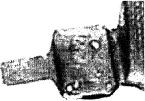
The male part of the seat belt assembly was redesigned and part of it was made out of steel in order to permit the belt to be picked up by the magnet. This change permits the presenter to automatically reset to its original position every time a user takes off the seat belt, by having the magnet attached to the arm attach to the seat belt assembly. Figure 4 shows a drawing of the seat belt.
Figure 4: Seat belt assemby of male part prototype by Petr Petri)
The belt is assembled by bringing together the plastic part show on the left of Figure 5 to enclose the aluminum sheet metal part in between the steel part on the right, creating the new seat belt, which attaches strongly to the magnet on the arms of the presenter.
Figrure 5: Hand drawn assembly of belt.
2.2 Motor and Sensors Mounting
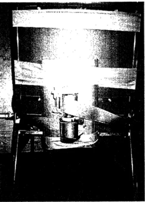
The mounting of the motor and the sensors required a light but strong metal to support their weight. It was decided to use an aluminum sheet as the mount in order to take advantage of its lightweight, ease of use, availability, and non-magnetic properties. In order to attach the mount to the uminum sheet, it was bent and laid on the chair. The mounting holes are drilled through the bent section of the aluminum sheet and the steel part of the chair using a hand drill. Using the drill press, the appropriate holes are made on the sheet in order to mount the Ford motor. Figure 6 pictures the mount with the arm and the sensors. Figure 7 pictures the motor attached to mount from a bottom view. Placing the mechanical sensors on the mount required the use of brackets. The brackets are built using the aluminum sheet leftover from the mount. Small strips are cut, bent halfxvay, and drilled twice on one of the bent sides for attachment on to the mount. Holes on the mount are also to allow the wire to be passed into the bottom of the chair and to mount the brackets. The non-drilled section is covered completely with the electrical tape to prevent the bracket from closing the circuit on the sensors when they are mounted, as can be seen in Figures 9 and 10. 1The mount, motor and sensor assembly can be seen through Figure 8.
down and seat belt is presented. The processes are described in detail as to the position of the arm and all the sensors (Note: sensor on means the mechanical switch is being pressed and off means it is not pressed). When the top and bottom position sensors are pressed the motor is stopped. For each process there is a drawing to show the position of the arm and the direction it rotates for each action.
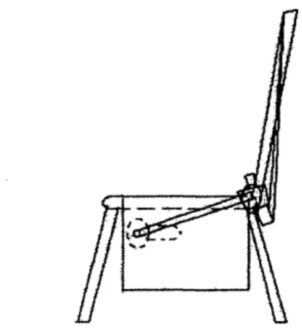
1) The seat is empty and the arm is at the resting position. Since there is no one on the seat, the seat sensor is off. The sensor that goes on the belt is on since the belt is attached to the magnet on the arm. The up position sensor is off and the down position is on since the arm is resting on it.
Figure 13: Orginal Postionfjr Seat Beft Presenter
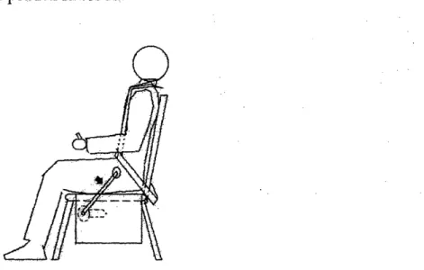
2) A person sits down and turns the seat sensor on. While the seat belt sensor remains on, the motor is activated by the seat sensor and begins to rotate the ann up. As a result this turns the down sensor off.
Fgturc 14: Person sits down and arm rotates .up
3) The arm reaches the top position and tuns on the up- position sensor. The only change between states two and state three is that the up position sensor is on- and- down position is off while person sensor and the seat belt sensor remain on.
Figure 15: Sea belt is presented
-4) Once the seat belt is removed the belt sensor is turned off. All other sensors remain the same, but the action of removing the seat belt activates the motor to rotate the arm- back down, thereby turning the up position sensor off.
Figure 16: Remoai the seat eft from magnet actiates tt motor to rotate back down.
5) After an returns to orinal position and-tumrns down position sensor on, thereby stopping the motor. The person sensor is on while the seat belt sensor is off This remains the same until the user removes seat belt and it returns to the magnet. his turns the seat sensor on and begins the cycle again.
3 Electrical Circuit Design Overview
3.1
Power Source
Originally, the control system design intended to regulate power to the motor through use of a car battery and an electrical adapter powered the logic circuitry. The design proved valid and demonstrated its capability to work as planned but failed to be simple and reduce cost since it required two power sources. The problem was resolved by using a 5-volt voltage regulator to power input to the logic. This permitted the use of the car battery to power both the motor and the logic. Implementation of the proposed design into an actual car would require a modification of the power source from the direct connection to the battery to connecting it through a fuse.
3.2
Logic
In order to arrive at the logic required to perform the actions desired, outlined in the operation process of the seat belt present, a table chart listing all the possible sensor positions for the four
sensors is made.
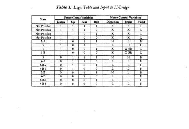
Table 1: Logic Table and Input to H-Bridge
State Sensor Input Variables Motor Control Variables Down Up Seat Belt Direction Brake PWM
Not Possible 1 1 1 1 X X L Not Possible 1 1 0 O X X L Not Possible 1 1 0 0 X X L Not Possible 1 1 O O X X L 2-A 1 0 1 1 H L H 5 1 O 1 0 L H H 1 1 0 0 1 X X(H) L 1-B 1 0 0 0 X X (H) L 3 0 1 1 1 H H H 4-A 0 1 1 0 L I. H 4-B-2 0 1 0 1 L L H 4-B-3 0 1 0 0 L L H 2-B 0 0 1 1 H L H 4-B 0 0 1 0 L L H 4-B-4 0 0 0 1 L L H 4-B-5 0 0 0 0 L L H 16
-.The logic is used to provide the input into the H-Bridge chip (discussed further in the next section), which takes as input three signals (direction, brake, and power). In addition to listing the sensor positions, for each possible combination a direction, option brake and power to the motor must be selected. The results are shown on Table 1.
The states listed on the left refer to the operational processes. The state whose number is followed by a letter indicates that it is part of a sub-process in that state. "e states that identified by a number and letter followed by another number, for. example 4--B2, are states that might occur if the process malfunctioned. This could happen if during the process of going betwveen states a variation occurs. In order to provide a control system that accounts :for such variations, a preventive measured is taken and the output to the H-bridge-is changed to account for the variation For example if the arm is rotating up to present -the seat belt but if it happens to get disengaged from the magnet, the control system then directs the motor to. stop and rotate: the- arm back to- the resting position in order to recover the seat belt. Should the seat belt not be th'ere because the user' picked it up and buckled up, then the sensors should take it to-:-fifth state, h-*the ann remains at the down position. Some of the possible variations that could occur are' having. a. per.s:on get off the seat or as-mentioned above, a seat belt gets disengaged off magnet. The states labeled 'Not Possible' show the different situations that could not occur unless a sensor broke down s-oewhere, therefore the. H-bridge inputs become irrelevant and the power to the motor is shut off. The Xs in. die input for the -I-bridge indicate that the case being referred to makes no difference as to what the output is, but .for some cases the X's were changed to off or low positions in order to simpli logic equations.
Evaluating the results of the table, we obtain the following equations for t-e direction, brake, and power inputs to the H-bridge:
SBUD +
U
+
BD
L
+SBLUD
+
SBUD = DIRECTION
Equation
1)
SBUD + SBU
D
+ SBUD + SB
UD
+
SBUD
+ SB UD =
P V
(Equation
3)
The lines above the letters indicate the sensor is off for that scenario. The letters S, B, U, and D refer to the sensors at the seat, belt, up position, and down position respectively. Equation 3, unlike the other two, indicates that the power is off whenever the cases shown arise. This reslts in the use of an inverter on the circuit to convert the signal from an off one to an on. Letters that are side by side indicate the AND logic function. For example, SBULD means that result of this will be a high (TRUE or ) only if S AND B AND U AND D are all on (1). The '+' sign in the equations is actually an OR logic function which will allow the given function to occur whenever any of those cases is true. After further simplification, the equations become the following
DIRECTION = SB (Equation 4)
BRAKE = SBUD +
SB
UD
(Equation
5)
F WM = UDS + UD
(Equation 6)
The equations were simplified to the conditions above by only having the variables (sensors) that they depend on in the equation showed. The equations can no-w be combined in order to provide the control system circuit diagram, drawn in Figure 18.
On the breadboard, the control system looks as pictured in figure 19 and figure 20.
-4 Further Work
4.1 Seat-Belt Presenter
The design proposed works to present the four-point seat-belt system well but for only one side, Work still has to be done to prototype the system for both sides. This might require coupling two motors for the two arms of the presenter to rise at the same rate. Additionally, thought has to go into whether the arms will have each react to the actions of the user jointly or separately. For example, if a user disengages the seat belt from one side first and then reaches for the other belt a couple of seconds later, whether the control system will lower both arms right after the first belt is picked up, or after both belts are picked up. The question of would each ann react individually after the belt is picked up has to be decided. Since our goal is to ensure that people buckle up, both arms should remain up until the two belts are removed from the magnets. An additional sensor should be installed on the belts in order to find out if people actually buckle up after detaching the two belts from the presenter.
In a real seat-belt presenter, the whole presenter assembly would have to be modified. 'ihe motor mount would be beneath the car seat. In contrast to our prototype, the actual seat-belt presenter would have the up/down sensors inside of the mount, underneath the seat, in order to prevent tampering. The seat sensor used for an actual presenter would have to be changed to a more appropriate one. Besides changing the method used to attach the ax;i to the motor, the arm would have to be made less wide. In addition, the magnet used worked properly but a separation of about 0.003 inches in order to make the force needed to separate the belt from it much smaller.
4.2
Motor
The Ford windshield wiper motor was used for its high torque. niual experiments conducted to find our the required torque on the seat belt presenter arm indicated a need of about 6.8 N-m to 10.2
N-m. The motor was chosen for having its stall torque of 14Nm. The disadvantage is the fact that it works at high revolutions per minute. To account for this, either the voltage supplied to the motor has to be reduced or another motor should be used. Should the Ford motor still be considered, after reducing the input voltage to an optimal quantity, tests should be done to ensure motor still has enough torque to drive the arms up and present the seat belt. In course of testing the prototype, the lap belt broke and accurate results could not be obtained. The belt failed to lock when pulled quickly. Though the motor may rotate too fast, using a 10-volt voltage regulator to reduce the input voltage into the H-bridge, which controls the motor, may be yield to desired results.
4.3
Changes to the Control System
The control system needs to be changed in order to address the issue of the second side of the presenter. The logic will now have to account for two up/down position sensors, two belt sensors, and possibly an extra sensor to determine whether the person buckled up or not. Two H-bridges might need to be used in order to drive two motors, that is unless an alternative motor can be found that can drive both arms at the same time is found (Note: Through gears, the same Ford motor could be used to drive both arms). Another issue that needs to be addressed is the introduction of delays. As is, the control system activates the motor and rotates the arm up immediately after the sensor is turned on. This poses the problem of having the arm rotate up when a person is in the process of sitting down and possibly cause harm to the person. The delay would give a person sitting down a few seconds before rotating the arm up. The LMD-18200 H-bridge being used is in need of a heat sink in order to prevent chip from burning. Though H-bridge automatically turns off once it reaches a certain temperature as a safety precaution, the correct functionality of the seat-belt presenter may be compromised. Lastly, the present control system is built on a breadboard but for use in real life, the control system would have to be put on a printed circuit and use smaller electrical components.
-5 Appendices
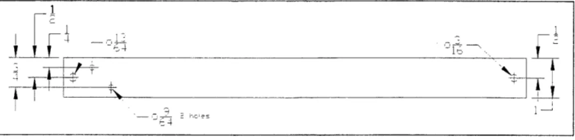
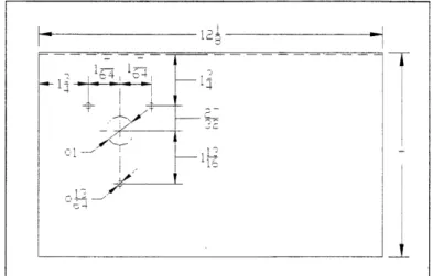
5.1 Appendix A (Part Drawings)
The following are the part drawing for the arm and the mount, two important parts of this thesis. Figure 22 and Figure 23 illustrate the top and side view of the arm. As for Figure 24, 25, and 26, they illustrate to top, side, and edge views of the mount. Of the characteristics on the mount missing from these part drawings are the holes to mount the sensors. They were not included since they are just there to serve the purpose of having the motor stop, the can be placed anywhere on a line in which the arm is desired to stop. The only requirement is that there are two holes on the brackets in order to ensure that the sensors don't rotate about one screw and have the motor not be able to come to a stop since the sensors stops it is not there anymore.
Figure 22: Part Drawing - Top Viewv of MechanicalArm
I-l I-l l, --2T i i I 4 i i I i a 4 HE he I£
Figure 23: Part Drawing - Front View of MechanicalArm
i I - ,,
Figure 24: Part Drawing - Top View of Mounting Plate
Figure 25: Part Drawing - Front View of Mounting Plate
~1
I__
:
Figure 26: Part Draring - Side View of Mounting Plate
24 -14 _ __ 113 -IP 4
?-~~~~~~~~~~I
-- - - - --1 - -- --4 n _- - - -'-- - - -I 12 i 1 -4 I , 7 1~~~~~ . 1 Ic5.2 Appendix B (Electrical Components)
The following is a list of electrical components used to built the control system: 1. Fairchild Semiconductor Hex Inverter Gates 74LS04 (1) 2. Fairchild Semiconductor Quad 2-Input AND Gate 74LS08 (2) 3. 78LO5Fairchild Semiconductor Quad 2-Input OR Gate 74LS32 (1)
4. Fairchild Semiconductor 5 Volt Voltage Regulator (1)
5. National Semiconductor 3A, 55V H-Bridge LM1D18200 (1)
6. Resistor 210 (4) 7. Resistor 470 Q (1) & Capacitor 10 nF
(2)
9. Capacitor 200 F (1) 10. Capacitor 0.33 gF (1) 11. Capacitor 0.1 j±F (1) 12. Capacitor 0.01 gF (1) 13. 3M Solderless Breadboard (1)14. Active Electronics Keyswitch (Mechanical) (4)
15. Red/\lhite Rolls 22 Gauge Wire (2)
16. Clear High Grade Speaker 16 Gauge Wire (1)
17. Electrical'Tape (1)
18. Mode Electronics 2-posinion .100" straight PC Header (2) 19. Mode Electronics 2-position wire connectors c/w contacts (2)
5.3 Appendix C (Control System Calculations)
Poweriq -te Loic.
LI · 5v: . -Swtch Open34
tfR
wift _4L SwitUi Cuza3 z*sI-Yet iO4 , -aLj-w
Yst
S
4ra.
}r,
I..r
I..
4 (v, 2e.
V). .n = T RI, 0.8 V R-T It+ zz
L. + J. 6.v .25W . R > 1t61 r tOSlFigure 27: Calul/ain tiof required resfistance into /ogic
-26
4.r Lov W
-X--jfi ;Al-
MA %
rh*esn 3.it. is Ore .J X L V f .· l t--5.4
Appendix D (Ford Windshield Wiper Motor Specifications)
The following data is for the Ford Motor used in the prototype. The motor was donated for this project by the staff of Course 2.007, Design for Manufacturing I. The data was obtained from the 2.007 Course Homepage. A part drawing of the Ford motor can be seen in Figure 28 and a Torque vs. speed graph is in Figure 29.
Clockwise:
No Load High Speed
@
13.8 volts (Yellow & White) 81 rpmStall Torque (Yellow & White) 7.5 N-m = 66.4 in-lbf
No Load Low Speed
@
13.8 volts (Black & White) 50 rpmStall Torque (Black & White) 14 N-m = 123.9 in-lbf
Counter-Clockwise:
No Load High Speed
@
13.8 volts (Yellow & White) 66 rpmStall Torque (Yellow & White) 5 N-m = 44.2 in-lbf
No Load Low Speed @ 13.8 volts (Black & White) No Data
Stall Torque (Black & White) No Data
Nominal Voltage 13.8 Volts
Overall Length 197 mm = 7.75 in Overall Height 101 mm = 4.0 in Shaft Mounting 1/4 - 20 X 1.0 Body Diameter 61 mm = 2.4 in Mounting Holes (3) 1/4 - 20 x 1.0 Overall Weight 1417 g = 3.13 lbs
Figure 28: Ford Motor Part Drawing
Figure 29: Ford Motor Torque vs. Speed curve in CW direction
28
-The Ford Wind shield W pe Mort
2
Ali dimensions in nches
Torque-Speed for Ford Motor, Black & White wires,
CW direction 14 12 10 = 8 4 2 0 0 1 0 20 30 40 50 Speed (RPM)
5.5 Appendix E (Electrical Component Data Sheets)
August 1986
Revised March 2000
BSEMICNU-Cn=cRTM
DM74LS04
Hex Inverting Gates
General Description
This device contains six independent gates each of which
performs the logic INVERT function.
Ordering Code:
OrderNumber Package Number Package. Description
DM74LS04M M14A 14-Lead Small Outline Integrated Circuit (SOl c). JEDEC MS-120, 0.150 Narrow
DM74LS04SJ M14D 14-Lead Small Outline Package (SOP), EIAJ TYPE I, 5.3rmm Wide
M74LSO4N N14A ] 14-Lead Plastic Duai-lnAine Package (PDIP), JEDEC MS-001, 0.300 Wide
Device also avalable in Tape a Reel Spci y by appendV m ihe ut ttw'" to the odg.cod.
Connection Diagram tV Al To 13 1 rl AS 12 A2 It 1 S A4 Y4 11 S AS
Di
I I'S 17 GMo I Function Table Y=A Input Output A . Y L H H LH - HIGH Lgic Levl
L LOW LIaC L
@ 2000 Fairchild Semiconductor Corporation DS006345 www.fairchildsel .li.com
r-0
X 0 X r. 01,
I.II'
--r-so.. k iI, -&.
II- r. f., -| _ _ ! . 10-L
Vb0-- - --! t 4 I I 3o Absolute Maximum Ratings(Note 1)
.4 Note 1: The 'Absolte Maximum Ratings' are those values beyond which
* Supply Voltage 7V the safely of the device cannot be guarantee. The device should not be
Input Voltage 7V operated at these Emis. The parametric values defined in the Electrical
Input Voltage 7V Characteristics tables are not guaranteed at the absolute maximum ratings. O Operating Free Air Temperature Range 0°C to +700C The 'Recommnded Operating Condllions- table wiI define the conditions
Storage Temperature Range -65C to +150°C for actual device operation.
Recommended Operating Conditions
Symbol Parameter Min Nom Max Units
VCC Supply Voltage 4.75 5 5.25 V
VIH HIGH Level Input Voltage 2 V
V1L LOW Level Input Voltage 0.8 V
IOH HIGH Level Output Current -0.4 mA
.,L LOW Level Output Current 8 mA
TA Free Air Operating Temperature 0 70 C
Electrical Characteristics
over recommended o ree artemperaturee a(unless o wise ed)
Symbol Parameter ConditIons Min TYt Max Units
(Note 2)
V Input Clamp Voltage Vcc Min, 1 = -18 mA -1.5 V
VOl HIGH Level Vcc s i, OH Mx7 2.7 3.4 3.4 V
Output Voltage VIL = Max
VoL LOW Level VCc = k I, = Max, 0.35 0.5
Output Voltage V = Min V
IOL = 4 mA Vcc " Min 0.25 0.4
It Input Curent Max Vcc Max. V = 7V 0.1 mA
nput Voltage
IIH HIGH Level Input Current Vcc Max. V 2V .7VA 20
tL LOW Level input Current VCc = Max, V - 0.4V -0.36 mA
los Short Circuit Output Current VOc = Max (Note 3) -20 -100 mA
CCH Supply Current with Outputs HIGH VCC = Max I1.2 2.4 mA
fCL Supply Current with Outputs LOW Vcc = Max 3.6 651 mA
Note 2: All stypits are at VCC 5V. TA 25°C.
Note 3: Not more than one output should be shoed a a tne. and the duratiorn should not exceed one secnd.
Switching Characteristics
at Vc = 5V and TA 25C
0I _________________________________RL=2kQ
Symbol Parameter CL 15 pF CL= 50 pF Units
{ Min Max Mln Max
tH Propagation Delay Time 3 10 4s
LOW-4o-HIGH Level Output
j
Propegation Delay T me10 3 . .HIGH-to-LOW Level Output
_ _ _ _ _ _ _ _ _ _ _ _ _
www.fairchildsemi.com 2
Physical
Dimensions
inches (millimeters) unless otherwise noted (Continued) 0.740-0.770 . . 11B6.D- 1.s5 0.090 (2.86) R1 R1'11
. r .PIN N. 1. 1/es.2 oa o.m o PAX 1
12.317) (.7?i) DEH OPTION 1 ARIA ImtX [w AIl U. PN O. 1 [DENT GRON WO2
14-Lead Plastic Dual-In-Line Package (PDIP), JEDEC MS-001, 0.300 Wide
Package Number N14A
Fairchild does not assume any responsibility for use of any circuitry described, no circuit patent licenses are implied and Fairchild reserves the right at any time without notice to change said circuitry and specifications.
LIFE SUPPORT POLICY
FAIRCHILD'S PRODUCTS ARE NOT AUTHORIZED FOR USE AS CRITICAL COMPONENTS IN LIFE SUPPORT
DEVICES OR SYSTEMS WITHOUT THE EXPRESS WRITTEN APPROVAL OF THE PRESIDENT OF FAIRCHILD
SEMICONDUCTOR CORPORATION. As used herein:
1. Life support devices or systems are devices or systems which, (a) are intended for surgical implant into the body, or (b) support or sustain life, and (c) whose failure
to perform when properly used in accordance with
instructions for use provided in the labeling,'can be rea-sonably expected to result in a significant injury to the
user.
2. A critical component in any component of a life support device or system whose failure to perform can be rea-sonably expected to cause the failure of the life support device or system, or to affect its safety or effectiveness.
www.fairchildseml.com
0
z
I
X.0
5-0) Ab z (0X5
C) 0 t) to CD U) www.fairchildsemi.com 0.250i.010~~7
~~~~/
1~~~
'~6.350*0.254)
I·
;mc-
N i
TM...
DM74LS08
Quad 2-Input
AND Gates
General Description
This device contains four independent gates each of which performs the logic AND function.
August 1986 Revised March 2000
Ordering Code:
Order Number Package Number ..- Ckg" s n
DM74LSO8M M14A 14ead Sa Ouine Inegiraed ircui (SOlO).1 JSDEC S-120, 0.150 Narow DM74LS08SJ.. Mi4D 14-Lead SmaU Out inePackage (S ), AJ TYPE i, 5.3mm Wdee
DM74LS08N N14A 14-Lad Plasic DUaMLin-Une Patckage (IPti), JED*C MS01, 0.300 Wide
oeveisr also tvaisbia in Tae ad RNlI Sp5clybappadiiO ad hile Mw b _0uhL- s e. o..
Q0 'D ·1 I
z
W.Connection Diagram
4 I1 A4 !-? ¥4 II M i? t0 Ii I.ThJ
-
I
I
J I-1 I'P-il
4 i a2 12 yzIIFunction Table
Y=AB Inputs utput_A ' :
l-a-
--
Y
L LL
H L L .-OW L. g L H H HLrai tOW U,~
.L:~~~~~~~~LunreH
2000 Fairchild Semiconductor Corporation S006347 www.fairchildsemt.com
- 32-vt 114 __ _____ I __ ____ ____ r I ---_
FLJ-I
-
m I 2 bAbsolute Maximum Ratings(Note
1)Note 1: The 'Absolute Maximum Ratings are those values beyond which Supply Voltage 7V the safety of the device cannot be guaranteed. The device should not be
Input Voltage 7V operated at these kalts, The parametric values dened In the Electrical
CharacteristIcs tables are not guaranteed at the abaute maximum ratings. Operating Free Air Temperature Range 0°C to +70°C The 'Recomnended Operatng Conditions' table will define the conditions Storage Temperature Range -65°C to +1500C fore devc o tn.
Recommended Operating Conditions
Symbol Parameter Min Nom Max Units
_/CC Supply Voltage 4.75 5 5.25 V
VIH HIGH Level Input Voltage 2 V
VnL LOW Level Input Voltage .. ... 0.8 V
10H HIGH Level Output Current -04 mA
IOL iLOW Level Output Current 8 mA
TA . Free Air Operating Temperature 0 ... __ 70 C
Electrical Characteristics
over rommended operain. ree aL- temperaur . (urt.eeoh ie noed. . ...
Symbol Pareaeter Conditions Min T Max Units
_______
~~~~~~~~~
2.)~~~~~~~~
_ _ _~~
_~~
_~~(Not.
VI Input Clamp Voltage Vcc =Mln.Ij u 18 A -1.5 V
VOH~ HIGH Level VC MmiN w Max. 2.7 3.4
Outpu Voltage VIM - in
VOL LOW Lve VCC il'n. 4X-Mx. 0.35 0.5
Ouput Voag VIL max V
_______ _____________________ I 0
4
vAV
C0=Mi0.25
OA______ Inut Current a Max Input V~ltage V Max, VI 7 V 0.1 naA
HIGH Level npt Curren V,- a Max. V = 2.7V 20 tiA
LOW Level Input Curren Vcc a Max. V1 = O,4V -0.36 MA
IS Short CWnA Output Current Vcr a Max (Note 3) -0-100 rnA
tCCH Suppy Curent with Outputs HIGH
1/00. MAX 2.4 4.8 rn
Ic jStpplyurrerw th uqpi" OW Va max 4.4 8.8 mA
Switching Characteristics
at V0 0 = 5V and TA __________________5C___
Symbol Parameoter CL115 pP CIL $0 pF Units
M~in Max MAin Max:
t" Pfopagaso Delay Tme 4 13 6 is8n
LCWto-HGH~ Level Outpu
tpHL Propagation Delay m311 18 n
HIGH-to-LOW Level Otput
Note 2: Al ypicals are at Vcc = 5V. TA - 25'C.
Note 3- Not mn Ihar one outpul should be shorled at a te. and the duration should not exceed one second.
www.fairchildsemi.con 2 co
0
IV, C30-Physical Dimensions inches (milimeters) unless othermse noted (ontinued) n· r ~ no .,. L- -- '- W nas- is.mj --*4 I u F 5 B M M0 ri'r f
A'
W'W LU W Lt5iJ IlUW am M1R =a tm s~ _/wi 7 TW I AL am se0a (22W 4 a& z ta- s tauftLA) 'i o-amer tLo I amT.re
w
M -'' -irls-'"Ws i (aa~14-Lead Plastic Dual-in-Une Package (P2DIP, JEECMS-01, 0.300 Wide Padtage Number N4A
Fairchild does not assume any responsibiity for use of any circuitry describeld, no circuit patent licenses are implied and Fairchild reseres the right at any me without notice to change said circuitry and specifications.
LIFE SUPPORT POLICY
FAIRCHLD'S PRODUCTS ARE NOT AUTHORIZED FOR USE AS CRITICAL COMPONENTS IN LIFE SUPPORT DEVICES OR SYSTEMS WITHOUT THE EXPRESS WRITTEN APPROVAL OF THE PRESIDENT OF FAIRCHILD
SEMICONDUCTOR CORPORATION. As used herein: 1. Life support devices or systems am devices or systems
which, (a) are intended for surgical implant nto the body. or (b) support or sustain life, and (c) whose failure to perform when promperty used in accordance with instructions for use provided in the labeling, can be rea-sonably expected to resut in a significant injury to the user.
2. A Ttical component in any component of a life support
device or system whose failure to perform can be rea-sonably expected to cause the failure of the life support device or system, or to affect its safety or effectiveness.
www.fairchildsmi.com a 40
r-0
0
c) K0 C0
N.) C) U' GI) www.farchildsemi.com 5-
34 -_ __ ____ L _____ ·__J~~~~ ... __ -----n
mm]June 1986
Revised March 2000
FA I RCH ILO
SEMICONDULCOR TM
DM74LS32
Quad
2-Input
OR Gate
General Description
This device contains four independent gatos each of which
performs the logic OR function.
Ordering Code:
OrderNumber PackageNumber Package Description
DM74LS32M M14A ' 14-Lead Small Outlne Integrated Circuit (SOIC), JEDEC MS-120, 0150 Nairrow
DM74L$32SJ M14I) 14-Lead Small Oline Pacage (SOP), EMAJ TYE 1, 53mm Wide DM74LS32N N14A 14-Lead Plasic Dualn-Line Package (PDIP), JEDEC. MS-01t, 0 0 Wide
Deces elso-avabl hi Tape and Reel Spedy by appetrilng the. uflkl ia-'X'toie ordeitngod .
Connection Diagram
Function
Table
Y=A+B Inputs Output A . B Y L L L L H H H . L H H H H 1 HIGH LOg LL L f LOW LogicLvrl
0 2000 Fairchild Semiconductor Corporation DS006361 www.fairchlMdsemi.comn
a
I-V) C Os N)I
0
;4 hM tD _ _.__ _ _1__ _ · II I I I i iAbsolute Maximum Ratings(Note 1)
Note 1: The Absolute Maximum Ratings" are those values beyond which
Supply Voltage 7V the safety of the device cannot be guaranteed. The device should not be
Input Voltage 7V operated at these limits. The parametric values defined In the Electrical
Characteristics tables are not guaranteed at the absolute maximum ratings.
Operating Free Air Temperature Range 0OCC to 70CC The Recommended Operating Conditions" table will define the conditions
Storage Temperature Range DSrC to 0 50C for actual device operation.
Recommended Operating Conditions
Symbol Parameter Min Nomr Max Units
Vcc Supply Voltage 4.75 5 5,25 V
VIH HIGH Level Input Voltage 2 V
VIL LOW Level Input Voltage 0.8 V
IOH HIGH Level Output Current 0.4 mA
oL LOW Level Output Current 8 mA
TA Free Air Operating Temperature 0 70 EC
Electrical Characteristics
over recommended operating free air temperature range (unless otherwise noted)
Typ
Symbol Parameter Conditions Min ( Max Units
(Note 2)
Vt Input Clamp Voltage Vcc 0Min, II0 018 mA 01.5 V
VOH HIGH Level Vcc Min, IOH 0 Max 2.7 3.4 V
Output Voltage VIH D Min
VOL LOW Level Vcc 0 Min, IOL 0 Max 0.35 0.5
Output Voltage VIL 0 Max V
1oL 04 mA, VCC 0 Min 0.25 0.4
II Input Current @ Max Input Voltage VCC Max, VI07V 0,1 mA
IiH HIGH Level Input Current Vcc OMax, VI 02.7V 20 0A
IlL LOW Level Input Current Vcc 0 Max, V 0 .4V C0.36 mA
los Short Circuit Output Current Vcc 0 Max (Note 3) C20 5100 mA
ICCH Supply Current with Outputs HIGH Vcc 0 Max 3.1 6.2 mA
ICCL Supply Current with Outputs LOW Vcc 0 Max 4.9 9.8 mA
Note 2: All typicals are at Vcc 05V, TA 25CC.
Note 3: Not more than one output should be shorted at a time, and the duration should not exceed one second.
Switching Characteristics
at Vcc 5V and TA 025[C
RL 02 kO
Symbol Parameter CL 015 pF CL 050 pF Units
Min Max Min Max
t
PLH Propagation Delay Tlime 3 11 4 15 ns
LOW-to-HIGH Level Output
tPHL Propagation Delay Time 3 11 4 15 ns
HIGH-to-LOW Level Output
~~~~~~~~~.
_ wwwfairchildsemi.com 2 3--j
!-Physical Dimensions inches (millimeters) unless otherwise noted (Continued) PM I -t at"' 0.141-t.tO ilt"- 13.- t0a 7 z E+3t te aj ) 0W. 1l"DG~n LW LJJULIL5 .J LU a-=) iF Hw"N WR ARI N. _ se rUalwm TYP "lI.
14.Lead Plastic Dual-in-Lne Package (PIP), JEDEC MS401, 0.300 Wide Packag lIumber NI4A
Fairchild does not assume any responsibtry for use of any circuitry described, no circuit patent licenses are mplied and Fairchild reserves the fight at any time without notice to change said circuitry and specifications.
UFE SUPPORT POcICY
FAIRCHIlD'S PRODUCTS ARE NOT AUTHORIZED FOR USE AS CRITICAL COMPONENTS N LIFE SUPPORT DEVICES OR SYSTEMS WITHOUT THE EXPRESS WRITTEN APPROVAL OF THE PRESIDENT OF FAIRCHILD SEMICONDUCTOR CORPORATION. As used herein:
1. Life support devices or systems are devices or systems which, a) are intended for surgical implant into the body, or (b) support or sustain fife, and (c) whose failure to perform when properly used in accordance with instructions for use provided in the labeling, can be rea-sonably expected to result in a significant injury to the
user.
2. A criticai component in any component of a life support device or system whose failure to perform can be rea-sonably expected to cause the failture of the life support device or system, or to affect its safety or effectiveness.
www.farchildsemi.com www.airchildsemi.com
a
9
4 A br
CA (a bo JD3 1: MC; N 0) toI laC)0
.4 GD 5 _ __ ___ ___~~ _I __ _ __ -_ - __ __w i · · K ·a · l w · J. __ . . . 2 = iif r_ .W -.rv7Er. : . -J
-, , , _ . , . - . --II " ' - -' 1.. I I In
FAIRCHI O
SEMICONDUCTOR TM
www.fairchildseml.com
MC78LXXAILM78LXXA
3-terminal
0.1A
positive voltage regulator
Features
* Maximum Output Current of 100mA
* Output Voltage of SV, 6V, 8V, 9V, 10V, 12V, 15V, 18V and 24V
* Thermal Overload Protection * Short Circuit Current Limiting
* Output Voltage Offered in ± 5% Tolerance
Description
The MC78LXXA/LM78LXXA series of fixed voltage monolithic integrated circuit -voltage regulators are suitable for application that required supply current up to l100mA.
Internal
Block
Diagram
2
Rev. 5.0
©2000 Fairchild Semiconductor International
TO-92 1 "
I
d
1: Output 2: GND 3: Input 8-SOP 1: Output 2: GND 3: GND 4: NC 5: NC 6: GND 7: GND 8: Input .MC78LXXAILM78LXXA
- ~ ~ ~ ...
Absolute Maximum Rati.gs
Parameter Symbol Value Unit
Input Voltage (for Vo = 5V, 8V) VI 30 V
(for Vo = 12V to 18V) 35 V
(for Vo = 24V 40 V
Operating Junction Temperature Range TJ 0 - +150 °C
Storage Temperature Range TSTG -65 - +150 °C
Electrical Characteristics(MC78L05ALM78L05A)
(VI = IOV, lo = 40mA, 0 °C < TJ < 125 °C, Cl = 0.33 ILF, CO =0.1 pF, unless otherwise specified. (Note 1)
Parameter Symbol Conditions Min. Typ. Max. Unit
Output Voltage Vo TJ = 25 °C 4.8 5.0 5.2 V
Line Regulation 7V V 20V - 8 150 mV
*AVo . TJ = 25 °C
8V ; VI < 20V 6 100 mV
AVo 1mA rio 1 00mA - 11 60 mV
Load Regulation Tj = 25 °C
1mA
lO
mA - 5.0
30
mV7V VI 20V 1 mA ; lo 4OmA - - 5.25 V
Output Voltage Vo 7V I < VMAX 1mA 70mA 45.25 V
.(Note__2__ImA < Io < 70mA 4.75 - 5.25 V
Quiescent Current IQ Tj = 250 - 2.0 5.5 mA
Quiescent Current with line AtQ 8V SVl 5 20V _ 1.5 mA
Change f'with toad AIQ 1 mA lo 40 mA - - 0.1 mA
Output Noise Voltage VN TA = 25 C, 10Hz s f c 100KHz ' 40 - V
Temperature Coefficient of Vo AVO/AT lo= SmA - -0.65 - mV/°C
Ripple Rejection RR f = 120Hz, 8V < VI s 18V, Tj = 25 °C 41 80 - dB
Dropout Voltage VD. TJ = 25 'C - 1.7 - V
_
_ _. _ _ _ _ _ _ _ . . . I . , ,,
Notes:
1. The maximum steady state usable output current and input voltage are very dependent on the heat sinking and/or lead length
of the package. The data above represent pulse test conditions with junction temperature as indicated at the initiation of tests.
MC78LXXAILM78LXXA
Typical Application
INPUT
'( )': 8SOP Type Notes:
1. To specify an output voltage, substitute voltage value for "XX".
2. Bypass Capacitors are recommend for optimum stability and transient response and should be located as close as possible to the regulator
n
MC78LXXAILM78LXXA ..
~~~
... . ..Mechanical Dimensions
Package
TO-92
+0.25 4.58 -0.15 i' '"-L
0 <. 1.27TYP [1.27 ±0.20] 0.46 ±o.10 1.27TYP [1.27 ±0.20 L I +0.10 0.38 -0.05 ., . !i
L---. ...December 1999
National Semiconductor
LMD18200
3A, 55V H-Bridge
General Description
The LMD18200 is a 3A H-Bridge designed for motion control applications. The deviceis built using a mult-technology pro-cess which combines bipolar and CMOS control rcuitry with DMOS power devices on the same monorhlcslucture. Ideal for driving DC and stepper motors; the MD18200 ac-cornmmodates peak output crents up to 6A. An innovative circuit which facilitates low-loss sensing of theoutput current has been knplemented.
Features
mDelive rs up to 3A continuous output mOp erates at supply voltages up to 55V
· Lo w R {(ON) tyiically o.3n per switch aT TL and CMOS compatible nputs
*No shoot-through' current · T hermal warning -flag output at 145'C UT hermal shutdown (outputs off) at 170'C
win temal clamp diodes USho ted load protection
*in temal charge pump with external bootstrap capability
Applications
=DO and stopper motor drives uPosilfo n and velocity servomechanismsF actory automation -robots wNum etically controied machinery aCorn puter printers and ploters
Functional Diagram
T4ERUL FAG OUTPUT BOOTSTP
9 1
DIRECON
PWu
OUTPUT t Vs OUTPUT 2 800TUP 2
2 6 10 t1 CURRENT a8 SSE OUTPUT 7 GROUND
FIGURE 1. Functiona Block Diagram of LMD18200
1999 Natonal Sec uctor Crporadion DS010588
42
-
r-0
WI8
I -. Q1.3to
CD olastMa w.Moni.com _ __ __ ___Connection Diagrams and Ordering Information
BOOTSTRAP 2
.) OUTPUT 2
THERMAL FLAG OUTPUT
i· CURRENT SENSE OUTPUT
, __ ) GROUND VSPOWER SUPPLY PWM INPUT · BRAE INPUT . DIRECTION INPUT - OUTPUT 1 '...7 BOOTSTRAP 1 MZ
IOUNTING TAB CONNECTED TO GROUND (PIN 7)
1t-Lead TO-220 Package Top View
Order Number LMD18200T
See NS Package TAlB
BOOTSTRAP A-VOUT 1A-DIRECTION A-BRAKE A-PWM VS A-VS Signal GND B-Current Sense B-Thermal Flag 8-VOUT 2B-BOOTSTRAP 25-1 2 3 4 5 6 7 8 9 11 12 24 23 22 21 20 19 18 17 16 15 14 13 -- BOOTSTRAP 2A -VOUT 2A - Thermal Flag A -Curent Sense A - Signal GND A - Power GND A - Power GND B -PWM B -- BRAKE B -DIRECTION B -VBOOTSP B -BOOTSTRAP 18 oso"a4-s
24-Lead Dual-in-Line Package Top View
Order Number LMD18200-2D-QVV 5962-9232501VXA LMD 18200-201883 5962-9232501MXA See NS Package DA248
2 C3
0
2
0
C3 -J 11 10 9 8 7 6 5 4 3 2 _ 1* D;510#582 wwwnational.corn _I I I I ii..II.'--r
l ___ - -- --eAbsolute Maximum Ratings t
If MilltarylAerospace specified devices are
please contact the National Semiconductor Sa
Distributors for availability and specifications
Total Supply Voltage (V5, Pin 8)
Voltage at Pins 3, 4, 5, 8 and 9
Voltage at Bootstrap Pins
(Pins 1 and 11)
Peak Output Current (200 ms)
Continuous Output Current (Note 2)
Power Dissipation (Note 3)
Power Dissipation (TA = 25'C, Free Air)
red, Junction Temperature, T., )
icel ESD Susceptibility (Note 4)
Storage Temperature, TST G
60V Lead Temperature (Soldering, 10 sec.)
12V
Operating Ratings(Note 1)
Vour +16V Junction Temperature, Tj
6A Vs Supply Voltage 3A 25W 3W 150'C 1500V -40'C to +150'C 300'C -40'C to +125'C +12V to +55V
Electrical Characteristics (Note 5)
The following specifications apply for V, 42V, unless otherwise specified. Boldface limits apply over the entire operating
temperature range, -40'C S Tj 5 +125 C, all other limits are for T T =2'5C.
Symbol Parameter Conditions Typ Limit Units
Ros (ON) Switch ON Resistance Output Curent = 3A (Note 6) 0.33 0.4m106 (max)
Ros (ON) Switch ON Resistance Output Current = .6A (Note 6) 0,33 0.4 0.6 _ (max)
VCLP Clamp Diode Forward Drop Clamp Current = 3A (Note 6) 1.2 1.5 V (max)
Vr Logic Low Input Voltage Pins 3, 4, 5 -0.1 V (min)
0.8 v (max)
i, Logic i.ow Input Current VR =-0.1V, Pins = 3, 4, 5 -10 . .A (max)
V, _ Logic High Input Voltage Pins 3, 4. 5 2 V (min)
12 V (max)
IH Logic High Input Current V, = 12V. Pins = 3. 4, 5 10 A (max)
Current Sense Output lT = A (Note 8) 377 3251300 pA (min)
4251450 pA (max)
Current Sense Linearity 1A S l, S 3A (Note 7) ±6 ±9 %
Undervoltage Lockout Outputs tum OFF 9 V (min)
11 V (max)
T___ Warning Flag Temperature Pin 9 5 0.8V, IL= 2 mA 145 'C
VF(ON) Flag Output Saturation Voltage Tj TT, I, =2 mA 0.15 V
I,(OFF) Flag Output Leakage v, = 12V 0.2 10 pA (max)
Tjso Shutdown Temperature Outputs Turn OFF 170 'C
Is Quiescent Supply Current All Logic Inputs Low 13 25 mA (max)
too, Output Turn-On Delay Time Sourcing Outputs, lot, =3A 300 ns
Sinking Outputs, loi, =3A 300 ns
ton Output Turn-On Switching Time Bootstrap Capacitor = 10 nF
Sourcing Outputs, IuT =3A 100 ns
Sinking Outputs, Io =3A 80 ns
toon . Output Turn-Off Delay Times Sourcing Outputs, louT =3A 200 ns
Sinking Outputs, Io = 3A 200 ns
to Output Tum-Off Switching Times Bootstrap Capacitor = 10 nF
Sourcing Outputs, lout =3A 75 ns
Sinking Outputs, lo, 3A 70 ns
tow Minimum Input Pulse Width Pins 3, 4 and 5 1 ps
Ior Charge Pump Rise Time No Bootstrap Capacitor 20 _ps
3 "3
.0
o
o3 www.ntjonal.cm 44 -_ ___ - ---- IElectrical Characteristics Notes
Note 1: Absolute Maimumn Ratings indicate limits beyond which damage to the device may ocur. DC and AC electical spectfication do not apply when
op-erating the device beyond Its rated operating conditions.
Note 2: See Application Informntlon or dels regarding current limiting.
Note 3: The maximum power dissipalon must be derated at elevated lemperatures and Is a functlon of Tj(xl, ,, and TA.The mardmum allowable power
dis-sipatlon at any temperature Is PD 1)
=
(Tj(e -TAJjA. or the number gin n he Absolute Ratings, whchever s lower. The typcal themial resistance ftom
junc-tion to case (Jc) is 1.O'C/W and from junction to ambient (A) is 30 CN. For guaranteed operation Tmx) =125'C.
Note 4: Human-body model. 100 pF discharged through a 1.5 k resistor. Except Bootstrap pins (pins 1 and 1) which are protected to 1000V of ESO. Note 5: Al lits are 100% production tested at 25'C. Temperature extreme limits are guaranteed via correlation using accepted SOC (Sattical Quality Control) methods. AI limits are used to calulata AOL, (Average Outgoing Quality Level).
Note 8: Output currents are pulsed (tw <2 ms, Duty Cycle < 5%).
Note 7: Regulation is calculated retaive to the current sense output value th a 1A load. Note 8: Salecdtons for tighter toerance re available. Conact factory.
Typical Performance Characteristics
VSAT vs Flag Current
a I 30 o it 200- I i3C-5 0
11111
1.5 20 25 3.0 5.5 D 4.S 5. rFG CUDT (mA) Supply Current vs Supply Voltage E'i
I I I 20 I Hpr i =1 1 UPUTS LOI Ii i I 10 20 30 40 50 6O SUPPtLY VOLAGE VLTS) DWWLWNe1 Rs (ON) vs Temperature -55-35- 15 5 25 45 5 s5 tOS 125JUNCTlION £AH TSURE ('c)
DSOl5 17 Supply Current vs Frequency (Vs= 42V) 181 it
i
I ' - I I2-
M to too SWITCHINGC al0UENC (z) OW10811Z0 Roa (O?; vs Supply Voltage 0.40 F k, i I I I .3- 5'C i I I 0.3.* ] " 1 " -0.3' 0.385 I , I O-SD _ 0.33 0.52°'0l
e
_;d_
10 15 20 25 30 35 40 45 50 55 SUPPLY VOLTAGE DOOSUO5-1 y Current vs irature (V8= 42V) s I I d - -I a. : -35 -30 - 20 45 70 95 20 145JUNCETI" tCfPPRATURc (OC) ODoIuDSU21 Suppil Tempe a 19
i
Current Sense Output
vs Load Current Current Sense Operating Region
~4~0.I
2.5- IIs: U ~ ~ C 2.0;- 71 ! t|Lz
,.U t D.O tw-0.0 0.5 1.3 1 2.0 235 3.0LOAD tUI.EN1T (sAMPS1
t~~al2 &cCUutCY.,h--.
EI~E
25 50 1 100 125 150 JU1ICt[I0 TElUPATUR (fC) 050D10G52 4o
cm aJ.J
-4 200 - .a ' i i -r 3i iI wvm. natiorna.rom ___ I I I fall][ I . . 6 . Nz:-i
:i 2I Ia ie 8 f 1 A A rr 11 ft I,Test
Circuit
+5
INPL
Switching Time Definitions
INPUT +5V
o-J
3A SOURCE SINK xv SENSEO-
0'-OIPinout Description
(see Connecton Diagram)Pin 1, BOOTSTRAP I Input: Bootstrap capacitor pin for half
H-bridge number 1. The recommended capacitor (10 nF) is
connected between pins 1 and 2.
Pin 2, OUTPUT 1: Half H-bridge number I output
Pin 3, DIRECTION Input: See Table 1. This input controls
the direction of current flow between OUTPUT 1 and
OUT-PUT 2 (pins 2 and 10) and, therefore, the direction of rotation of a motor load.
Pin 4, BRAKE Input: See Table 1. This input is used to
brake a motor by effectively shorting its terminals. When
braking is desired, this input is taken to a logic high level and
it is also necessary to apply logic high to PWM input, pin 5. The drivers that short the motor are determined by the logic
level at the DIRECTION input -(Pin 3): with Pin 3 logic high,
both current sourcing output transistors are ON; with Pin 3
togic low, both current sinking output transistors are ON. All output transistors can be turned OFF by applying a logic high to Pin 4 and a logic low to PWM Input Pin 5; in this case only a small bias current (approximately -1.5 mA) exists at each output pin.
Pin 5, PWM Input: See Table 1. How this input (eand DIREC-TION Lnput, Pin 3) Is used is determined by the format of the
PWM Signa. 5 46