Design of an Unmanned
Aerial Vehicle
by
Jean-Marc C. Hauss
B.S. Mechanical and Aerospace Engineering & B.A. Physics
Cornell University, 1997
Submitted to the Department of Aeronautics and Astronautics in partial fulfillment of the requirements for the degree of
Master of Engineering
at the
Massachusetts Institute of Technology
June 1998© Jean-Marc C. Hauss, 1998. All Rights Reserved
The author hereby grants to MIT the permission to reproduce and to distribute publicly paper and electronic copies of this thesis document in whole or in part
Author
Department of Aeronautics and Astronautics
Certified by
Charles Boppe Senior Lecturer, Department of Aeronautics and Astronautics
I Thesis Supervisor
Accepted by
Jaime Peraire Associate Professor Chairman, Department Graduate Committee
Design of an Unmanned
Aerial Vehicle
by
Jean-Marc
C.
Hauss
Submitted to the Department of Aeronautics and Astronautics on 22 May, 1998, in partial fulfill-ment of the requirefulfill-ments for the degree of Master of Engineering
Abstract
Information gathering is becoming one of the growing assets for the military in combat situa-tions. America's vast intelligence network provides it with a way to quickly and efficiently
per-form sensitive military exercises. One area lacking in this domain is in rapidly obtaining information on events happening not far from the frontline. For instance, today's military com-mander would have to go through far away bases to obtain information on the location of enemy troops that are a few miles away.
One of the main objectives of the project behind this thesis was to provide the US Armed Forces and more specifically the Navy with a quick, cheap way to perform visual, short range reconnaissance missions. The concept is to launch an artillery shell containing a miniature unmanned aircraft right over the desired location. The advantage of this concept is that a recon-naissance mission can be done quickly, at low cost, and without requiring any landing strip. Major considerations in obtaining such a product are the high impulse forces affecting the aircraft during the artillery launch, and having to package a fully deployable aircraft inside a size-constrained shell.
Thesis Supervisor: Charles Boppe
Acknowledgments
I would first like to thank Draper Laboratory for giving me the opportunity to take part in this project. It is not common for a group of students to be able to take part on such a large project. This has been a very beneficial learning experience for someone about to embark into industry.
I would also like to thank professors Deyst and Boppe for their help and guidance throughout the year.
I also thank the team and especially its manager Sebastien Katch for having taught me the art of making an acceptable technical drawing.
Finally, I thank my parents and my brother for supporting and encouraging me in these past few years.
Table of Contents
Abstract... ... 3
Acknow ledgm ents... ... 5
Table of Contents ... ... 7 List of Figures ... 11 List of Tables ... 13 Chapter 1 Introduction... 14 1.1 M IT / Draper Partnership... 14 1.2 Project G oals ... 15
1.3 W ork Perform ed during First Year... ... 17
Chapter 2 Project Description... 18
2.1 General Project D escription... 18
2.1.1 Concept D escription... 18
2.1.1.1 Typical M ission Scenario.. ... 18
2.1.1.2 D esign Challenges... 19
2.1.2 The Proof of Concept Test Vehicles... 20
2.1.2.1 H igh-g Vehicle... 21
2.1.2.2 Flight Test Vehicle... 24
2.2 Team Breakdow n ... 26
2.2.1 Back-End M odule... 26
2.2.2 Tail M odule ... 28
2.2.3 W ing M odule ... 29
2.2.5 Aircraft Stability and Communications... 31
2.2.6 Internal Structure... 32
2.3 Overview of Project W ork... ... 33
Chapter 3 Power System s... 35
3.1 Flight Test Vehicle... 35
3.1.1 Pow er Requirem ents... 35
3.1.2 Battery selection... 38
3.1.2.1 Battery Type Selection... .... ... 38
3.1.2.2 Battery Quantity Calculation... ... 39
3.1.3 Power M odule Design... 41
3.2 High-g vehicle ... 43
3.2.1 Power Requirem ents... 43
3.2.2 Power Source Selection... 44
3.2.3 Power Board Design... 45
3.3 Operational Vehicle... 46
3.3.1 Power Requirem ents... 46
3.3.2 Battery Selection... 48
3.3.3 Power Board Design... 49
Chapter 4 Tail A ctuators... 51
4.1 Servo-M otor Selection... 51
4.1.1 Servo Requirem ents... 51
4.1.2 Servo Testing ... 52
4.2 Gear Selection ... 56
4.2.1 Gear Specifications... 56
4.2.2 Gear Calculations... 56
4.2.3 Gear Selection ... 57
4.3 Tail and Gear Integration... 58
5.1 Defining the Need for a Back-up Plan... 61
5.1.1 Initial Selection of the M eans for Propulsion... 61
5.1.2 Status of the Gas Engine Design... 61
5.1.3 Obstacles in Gas Engine Design... ... 61
5.1.4 Advantages of the Electric M otor... 62
5.2 Electric M otor Selection... 62
5.3 Battery Selection for Electric M otor... 66
5.3.1 Battery Type Selection... 66
5.3.2 Cell Size Selection... 68
5.4 Testing and Results... 69
Chapter 6 Overall Testing Results... ... 72
6.1 Testing of Individual Components... ... 72
6.1.1 Tail M odule Testing... 72
6.1.2 W ing Testing... ... 73
6.1.3 Testing of other Components.. ... 73
6.2 System Testing ... 74
6.2.1 Flight Test Vehicle... 74
6.2.2 High-g Test... 74
Chapter 7 Conclusion... ... 76
7.1 Lessons Learned ... 76
7.2 Concluding Rem arks... 77
Appendix A: Cavity Dimension Calculation from Tool Diameter Considerations... 79
Appendix B: Matlab File Computing Motor Output Characteristics... 81
List of Figures
Figure 1: Sequence of Events Leading to a System Selection... 15
Figure 2: Sequence of Events for Concept Design and Development... 16
Figure 3: D eploym ent Sequence... ... 19
Figure 4: Concept D em onstration... ... 21
Figure 5: Air Gun at Picatinny Arsenal... 22
Figure 6: A ir G un C anister... 23
Figure 7: Configuration of FTV... ... 24
Figure 8: Control Architecture of FTV... 25
Figure 9: Shell with Six Fins Deployed and Flyer... ... 27
Figure 10: Parachute Deployed in Wind Tunnel... ... 28
Figure 11:Tail M odule... 29
Figure 12: Stowed Wing Inside Flyer... 29
Figure 13: Wing Deployment Sequence... 30
Figure 14: Propulsion M odule... ... 31
Figure 15: Software Architecture for Operational Vehicle... ... 32
Figure 16: Modular Structure of Flyer... 33
Figure 17: C am era Test A rticle... ... 34
Figure 18: B attery Lifetim e... ... 40
Figure 19: FT V B attery... 4 1 Figure 20: FTV Power Board Circuit Diagram... ... 42
Figure 21: Power Board Inside FTV... 43
Figure 22: High-g Vehicle Power Board Design... 45
Figure 23: Illustration of Moment Arm... 51
Figure 24: CAD Drawing of Test Article for Servos... ... 54
Figure 25: Test Article for Servos... ... 55
Figure 26: Worm and Worm Gear Combination Selected... ... 58
Figure 27: Positioning the Servo inside the Tail Module... ... 59
Figure 28: Servo Mounted Inside the Main Part of the Tail Module... . 60
Figure 29: Test Article for Electric Motor... 69
Figure 30: Test Article for Speed Controller. ... 70
Figure 31: Illustration of Battery Test... 70
Figure 32: Tail Module Tested in Air Gun... 72
Figure 33: Wing Section Tested in Air Gun... ... 73
Figure 34: D ahlgren G un... ... 74
Figure 35: Canister after Dahlgren Test... 75
Figure 36: Flyer after Dahlgren Test...75
Figure 37: The Author Holding the Flyer before High-g Testing... 77
Figure 38: Illustration of Gap Due to Tool Diameter... ... ... 79
List of Tables
Table 1: FTV Power Requirem ents... ... 35
Table 2: Determining the Total Power Requirements... ... 37
Table 3: Rechargeable Batteries Characteristics... 38
Table 4: Battery Lifetime vs. Number of Batteries... 40
Table 5: High-g Vehicle Power Requirements... 44
Table 6: Operational Vehicle Power Requirements... ... 46
Table 7: Operational Vehicle Maximum Power Required... ... 47
Table 8: Eagle Picher High-g Batteries... 48
Table 9: Servos Tested in A ir G un... 53
Table 10: Testing Results for Servos... ... 55
Table 11: Possible Gearing Combinations... 58
Table 12: M otor Characteristics... ... 66
Table 13: Eagle Picher Thermal Batteries... 67
Introduction
This thesis serves as an overview of the work done by the WASP (Wide Area Surveillance Projectile) team on the design of a surveillance projectile. It will describe, in greater details, the work done by the author.
The first chapter will give a background of the project and how it came about. It will also go over the work performed in the first year of this two year project. It briefly describes how the con-cept of a gun launched unmanned aircraft was selected.
Chapter two gives a more detailed description of the technical aspects of the project. It includes the different tests used to demonstrate the validity of the design. This chapter discusses the different project components. An overview of the author's work on the project is then pro-vided.
The next three chapters go into details describing the author's part of the project. Chapter three describes how the power systems for the different vehicles were designed. Chapter four goes over the system selected for the tail actuators. Chapter five looks into the backup plan for the pro-pulsion system.
Chapter six goes over all the testing results for the different parts of the project. The results for the final system testing are also included.
Chapter seven discusses the conclusions and the lessons learned for the project.
1.1 MIT-Draper Partnership
The project behind this thesis is funded and supervised by Draper Laboratory. The association between Draper Laboratory and MIT is long-standing as Draper Laboratory initially was an inte-gral part of MIT. The MIT/Draper Technology Development Project was created in the Summer of 1996 to consolidate this cooperation between Draper and MIT's Aeronautics and Astronautics Department.
About ten students were to work on a project for two years. There were five Master of Science students and another five Master of Engineering students, with a few undergraduate UROPs help-ing out. The Master of Engineerhelp-ing is a one year program. Two different sets of MEng students worked on the project. Being one of those Master of Engineering students, the author joined the team for the second year.
1.2 Project Goals
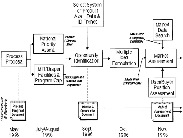
The project's main requirement was to design a nationally important aerospace system in two years time. One of the project's characteristics is that it had to include a high level of "unobtain-ium," or a high level of risk. For the first set of students working the first year, the initial task was to come up with a set of projects satisfying these requirements and perform a feasibility analysis. This was done during the first six months of the project. Figure 1 shows the tasks performed for this first part.
Select System
or
Product
Avail.
Date
&
ID Trends
Market
Data
''
Search
National
'
-
er
Jcm.PPriority
Process |
1 .1 Opportunity
Multiple
Market
Proposal
Identification
Formulation
Assessment
MIT/Draper
Formulation
Facilities &
Program
Cap.
C, ,,,,
A
,,,, ,,,,, ,
Userwuer
UseriBuyer
Position
Assessment
Process
Pr ornk
"
Maket
Prooal qOporiall A essment
Docurni o11 an I Docu C t1
May
July/August
Sept.
Oct.
Nov.
1996
1996
1996
1996
1996
Figure 1: Sequence of Events Leading to a System Selection
At this point, the fast response surveillance projectile was selected. This marks the beginning of WASP. During the next six months, the team came up with different concepts for the flyer. The final concept chosen was that of a vehicle fitting inside an artillery shell. This marked the end of
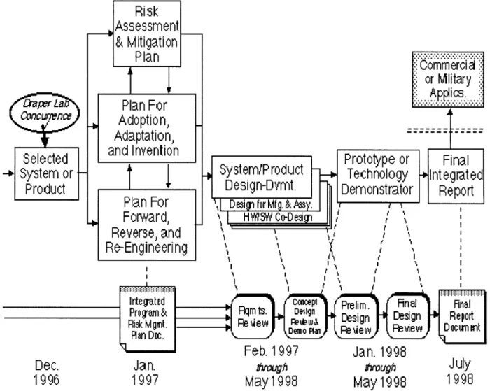
the work for the first year students. At this time, the second set of students, joined the project team. In the first six months of the second year, the detail design of all the different components was performed. Finally, the last six months comprised experimental testing of all the parts, and putting together all the components into a system. The sequence of events for the second part of the project, the design of WASP, can be seen in figure 2.
Risk
Assessment
Feb. 1997
Jan. 1998
Dec.
Jan.
arough
trvughJuly
1996
1997
May
1998
May
1998
1998
Figure 2: Sequence of Events for Concept Design and Development
The final objective was to come up with a working prototype demonstrating the feasibility of the concept.
5 r
1.3 Work Performed during First Year
First year work consisted mostly of selecting a system to design, and an initial analysis of the feasibility of this design.
The team first looked at different concepts that fit the requirement to design a high risk proto-type satisfying a national need. Some of the concepts considered were a solar sail, a search and rescue vehicle, and a method to send vehicles into orbit by launching them from the high atmo-sphere. As discussed, the final concept selected was a rapid response vehicle that could provide short range reconnaissance. The system's benefits were that it would provide a reconnaissance capability in a short amount of time, and could do it for a fraction of the cost of existing systems.
To provide a rapid response, the projectile would be launched from a gun. Different concepts were then considered. Some of the options were to use a composite shell, have a sabot protect the flyer when inside the gun, or have the flyer inside an artillery shell until it is to be deployed. This last option was chosen.
Another important task completed during the first year involved selecting what technology should be used to perform different functions in the final vehicle. This consisted of an analysis of different ways to perform different operations. For example, an analysis was performed on how to propel the flyer. Rockets, gas engines and electric motors were all considered as candidates. By
analyzing the advantages and disadvantages of each mode of propulsion, the gas engine was selected. Another such analysis was performed on how to stow the flyer's wings before being deployed.
Project Description
The goal of the project was to design a fast-response reconnaissance unmanned aircraft. The underlying method is to fit the aircraft inside an artillery shell. This chapter gives a description of the project as a whole and where the author's responsibilities lie.
2.1 General Project Description
2.1.1 Concept Description2.1.1.1 Typical Mission Scenario
With the work performed during the first year of the project, a relatively accurate mission sce-nario was obtained. This description of a typical scesce-nario will give a good feel of what this project is about. The following description represents the project as it stood when the author joined the team in September 1997. As aforementioned, the vehicle is initially inside a five inch Navy artil-lery shell and is stored that way until it is to be used. The shell is fired at the request of the ship's captain or battalion commander. As the projectile exits the gun barrel at 680 m/s, fins located at the back of the shell deploy to allow for a stable projectile. Then somewhere around the peak of the trajectory, the back part of the shell separates with an explosive bolt. Shortly thereafter, a para-chute is deployed to decelerate the vehicle from 340 m/s to around 50 m/s. The parapara-chute also has the effect of removing the flyer from the surrounding shell. Once the vehicle is outside the shell, a propeller driven by an engine starts, two foldable wings deploy and two tails deploy. Once the vehicle is a deployed flyer, the engine and the electronics are started. From here, the aircraft flies on its own and takes pictures which are relayed back to a ground station. An illustration of this
Separation
Parachute
Flyer
Deployment
Separation
Wing Unfold/
Controlled Flight
c
Launch
Mission
Figure 3: Deployment Sequence
This represents the backbone of a typical scenario. Different considerations were taken to allow for different missions. For instance, the parachute could be deployed at different times, or the plane could perform different search patterns from its deployed state.
2.1.1.2 Design Challenges
The major technical requirement was to design a vehicle that could withstand the initial artil-lery launch. This initial force can be separated into different components. First there is the for-ward axial acceleration which is a seventeen millisecond pulse of 15000 g's. This is the largest force and hence the one given the most consideration. Then there is a backwards axial accelera-tion represented by a shorter pulse of 4000 g's, called setback. This comes about from the com-pression of the shell under the initial acceleration. The rear of the shell accelerates faster than the
front which compresses the shell. Finally there is a radial vibration with a peak amplitude of 1000g's. This comes from the spinning of the shell inside the gun barrel. This g-loading require-ment applies to the whole vehicle and was a major concern.
Another main design challenge is to have all the components fit inside a standard military shell which is the five inch shell in the case of this flyer. The five inch shell was chosen since it is the one used most often by the intended customer, the Navy. This means that the flyer has to be even smaller than the five inch diameter, two feet long shell. Everything from the wings to the propulsion system and the electronics have to fit inside this small volume.
These requirements make for a state-of-the-art design problem with nothing of the sort ever having been done. Some projectiles using the concept of firing something inside an artillery shell have already been designed. For instance, there exists an illuminating round which is used to illu-minate a battle field. This is basically a flare inside an artillery shell which is fired, deploys, and then slowly descends while being held up by a parachute. Ideas from this design, such as the design for the back of the shell were used. But this design comes nowhere near the complexity of having a small scale aircraft deploying from a shell.
2.1.2 The Proof of Concept Test Vehicles
The demonstration of the functionality is done by performing two types of tests. For all the structural and flyer separation demonstration there is the high-g test. For the avionics and aerody-namic performance, there is the Flight Test Vehicle. These two series of tests are then put together into the operational vehicle, which is the final working vehicle (figure 4). This operational vehicle is only a paper design because most of the high-g qualified electronics were still unavailable at the time of the design.
Operational Vehicle
@Complete Design
SChallenges:
1. High-g survivability
2. Hying qualities
High-G Vehicle (HGV)
Flight
*G-hardened structural, mechanical,
@Demons
propulsive, and deployment systems
aerodyna
*Onboard electronics proven on CMATD
@"Off the
augmenti
cost
Test Vehicle
(FTV)
trate flying qualities and
mic performance
shelf" electronics for stability
ation system and telemetry to reduce
/
.1
Figure 4: Concept Demonstration
2.1.2.1 High-g Test Vehicle
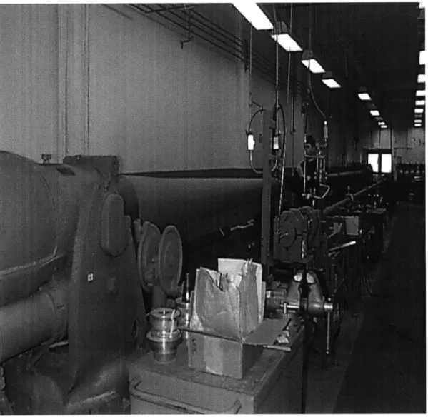
The high-g test vehicle is used to verify the structural response of the operational vehicle under the gun launch. It is also supposed to verify all the separation mechanism. This includes extracting the flyer out of the shell, deploying the wings, and starting the engine. First there is a series of high-g tests for individual components to see if they can withstand a gun launch. To this extent, the Air Gun at Picatinny Arsenal in New Jersey was used (figure 5).
Figure 5: Air Gun at Picatinny Arsenal
The air gun can give the 15000 g's with a two ms pulse. This isn't identical to the real Navy gun characteristics. The Navy gun has about a seventeen milliseconds pulse and in addition gives the 4000 g set-back acceleration which isn't felt in the Air Gun. Nonetheless the Air Gun was used since the cost is $1000 per test compared to around $40000 for the real gun. In addition,
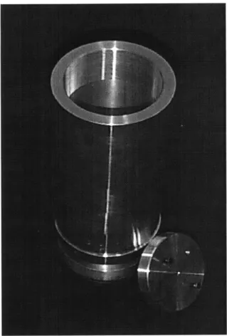
since the project is performed by a university, the team was able to secure twenty-eight of these tests for free. For this series of tests, the component to be tested is placed inside a specific canister (figure 6) that fits inside the Air Gun. The typical procedure is to test an article at different accel-erations. To this extent each test article would usually be tested three or four times, starting at accelerations around 5000 g's and slowly increasing the acceleration to about 15000 g's.
Figure 6: Air Gun Canister
A second series of tests would be used to verify the separation sequence. There are a few options for this. A drop test could be performed where the shell is dropped and the separation is performed at the right speed. Another option is to fire a real shell to verify the separation. At the time this thesis was completed, these tests had been deferred, mostly because the separation required the use of explosives. The team had difficulties obtaining the services of professionals qualified to handle explosives.
All of these tests are combined to verify the system as a whole. At first, the plan was to have the whole flyer, without the avionics, put inside a shell and fired from the real gun. The goal was to have the flyer come out of the shell and fly. No pictures were to be taken and the avionics
weren't supposed to be included since none of these components would be available in g-hard-ened form. Eventually because of costs, and concerns with the explosives to be used in the
deployment sequence, this test would be scaled back to a canister test in the real gun. The advan-tages of this test relative the air gun tests were that the real gun acceleration would be felt by the flyer, and the whole assembly would be tested.
2.1.2.2 Flight Test Vehicle
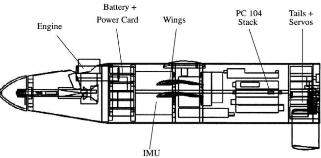
The Flight Test Vehicle (FTV figure 7) is supposed to test everything that could not be tested in the high-g environment. This includes the aerodynamic performance, the stability augmenta-tion, the unmanned vehicle aspect and taking pictures with the camera. To that extent the FTV is
an aircraft similar to the final operational vehicle that is not high-g qualified. At first, the aircraft will be a remote controlled aircraft commanded by a ground based pilot. This will allow for the testing of the aerodynamics and stability augmentation. Once this is done, the aircraft will no longer be controlled by the pilot but by the on-board CPU. This will prove the un-manned aspect. Finally, the camera will be integrated and will relay the pictures taken back to a ground station. This is to prove the ultimate functionality of the flyer.
The FTV is a 128% scaled up version of the final vehicle because some of the avionics, such as the IMU selected, could not fit inside the real vehicle. This scaling was done while keeping all the important aerodynamic characteristics identical.
Battery + PC 104 Tails +
Power Card Wings Stack Servos
Engine
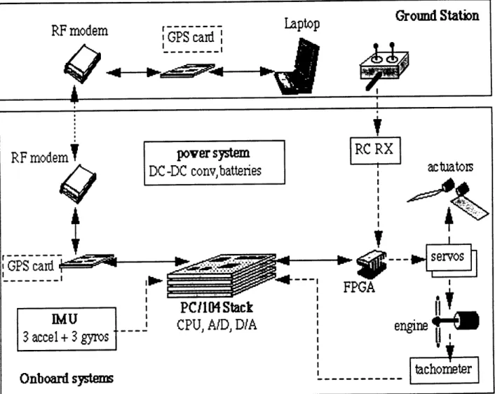
Figure 8 shows how the FTV will operate. There are two ways to control the aircraft. Either the pilot sends the command to the aircraft through the transmitter, or the aircraft is controlled by the on-board computer. An FPGA chip allows the pilot to toggle between these two control modes. There are three actuators that allow for the control of the aircraft. There are the two tail servos and the engine servo. All of this is very similar to what is supposed to happen on the final operational vehicle. The main modification is the use of a transmitter and the FPGA chip. In the operational vehicle, all commands are given by the computer, and there is no pilot.
Ground Station
RF modem
GPS card
-
Laptop
RF modem
pover
system
RC RX
DC-DC convy,batteries
actuators
GPS card ;79Pv
PCIl04Stack
i
c U
CPU, AID DIA
engine
3 accel + 3 gyros
Onboard systemsach
2.2
Team Breakdown
The work was broken down according to parts of the design. One big part dealt with the back part of the shell. This part comprises work on the parachute, the retrieval of the aircraft from the
shell, and the stabilizing tail fins. Another part is designing the wings. This includes the aerody-namics as well as the folding mechanism. Next, there is the propulsion system which comprises designing the engine and everything that comes with it (starter, gas tank, glow plug and propeller deployment). Another important section is the stabilization of the aircraft and the avionics that
comes along with it. Finally everything has to be put together, meaning that some sort of internal structure of the aircraft had to be designed. Each of these sections were assigned to specific teams. The break up of the work lead to the modularisation of the vehicle, with a certain section of the vehicle being assigned to different teams. This allowed the teams to move ahead with their designs without being affected too much by the design changes of some other part. These differ-ent parts are described hereafter in more detail.
2.2.1 Back-End Module
The team taking care of this part is made up of Garret Shook and Rodney Chiu. This is the module that fits on the end of the shell and is separated from the rest of the shell before the flyer is deployed. There are many important parts to this module.
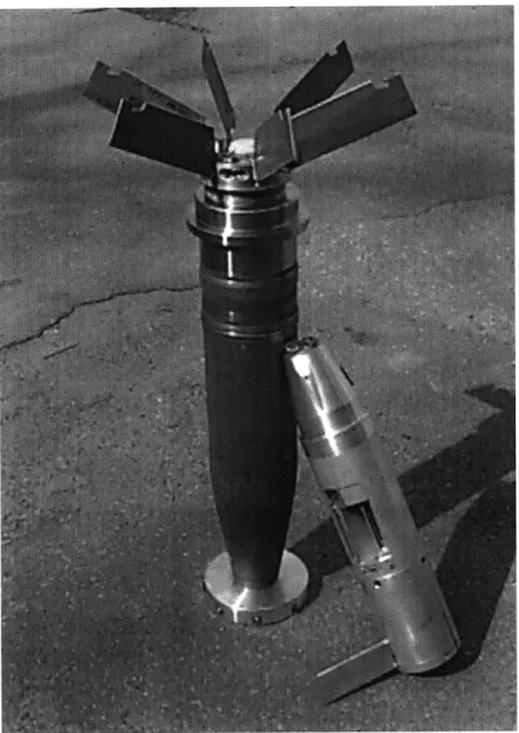
First there are the stabilizing fins. Without any fins, the shell is unstable since the center-of-pressure is in front of the center-of-gravity. Although the fins make the shell stable, they increase the drag, which reduces the overall range. In addition, the fins have to deploy as soon as the shell exits the barrel. Six finsi are used in the design as can be seen in figure 9.
1. Shook, Garrett, Design, Assembly and Test of a Launch and Flight Support and Deployment System for a Gun-Launch Reconnaissance Vehicle, Massachusetts Institute of Technology, Cambridge, MA, June,
Figure 9: Shell with Six Fins Deployed and Flyer
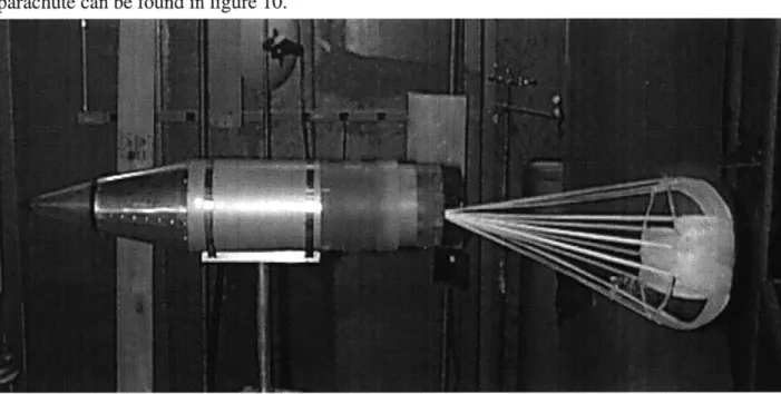
Then the parachute is an integral part of this back end. The parachute has two tasks. It must slow down the vehicle from a velocity of Mach 2 to 50 m/s. It must also pull the flyer out of the shell. Calculations showed that this required a force of 300N. The parachute was designed with the help of Butler Parachute Systems which designs parachutes for military applications. The final
result was a kevlar parachute attached to the flyer with a swivel joint1. Wind tunnel testing of the parachute can be found in figure 10.
Figure 10: Parachute Deployed in Wind Tunnel
The final task for the back-end was to design the attachment of the back-end to the rest of the shell as well as the separation mechanism.
2.2.2 Tail Module
The tail module includes the tails and most of the electronics. The team taking care of this part comprised Sebastien Katch and myself. This team had the responsibility of designing the deploy-able tails and packaging most of the avionics in the tail (figure 11). At first two V-tails were cho-sen as the lone control surfaces for the aircraft. With V-tails, both longitudinal and lateral control could be obtained with only two control surfaces. Later on, the design incorporated a set of two rudders because of lateral instabilities. While the two V-tails are control surfaces (provisions were made so that they can rotate), the rudders are only there for stability purposes and remain fixed during flight. All the rudders and V-tails are designed to deploy as soon as the flyer exits the shell. This is done with a spring loaded pivot. The design of the motion for the V-tails was performed by the author and will be discussed in more detail later on.
1. Chiu, Rodney, WASP Deployment Sequence, Massachusetts Institute of Technology, Cambridge, MA, August, 1998
Figure 11: Tail Module 2.2.3 Wing module
The team designing the wings was Stacey Jenkins and Thierry Casiez1. To this extent, the whole middle section of the vehicle was reserved for the wings. For the wing design, the major constraint is that they have to be completely enclosed within the five inch shell diameter (figure
12). Two concepts that were initially studied were the foldable wing and the inflatable wing. Dur-ing the Summer, the foldable wDur-ing concept was selected and incorporated into the design.
Figure 12: Stowed Wing inside Flyer
1. Casiez, Thierry, Compact, High-g, High Efficiency Folding Wing for a Cannon-Launched
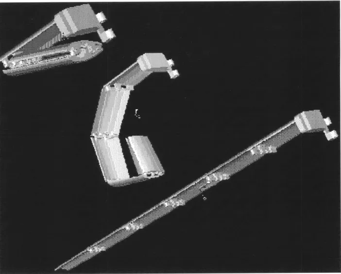
The wings consist of six airfoil sections attached together by hinges. These spring loaded hinges allow for the whole wing to unfold (figure 13).
Figure 13: Wing Deployment Sequence
2.2.4 Cone Module
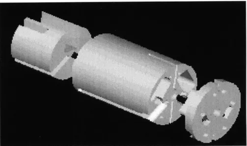
The design of the cone module was performed mostly by Torrey Radcliffe. This cone module includes most of the propulsion unit, which is a gas engine. After testing a few engines in the Picatinny Air Gun, the two-stroke was selected. In addition to incorporating this engine in the cone, a foldable propeller, a staring mechanism, a gas tank, a glow plug and a servo for the carbu-retor are all needed (figure 14).
Figure 14: Propulsion Module
2.2.5 Aircraft Stability and Communications
The team taking care of all the software and the aerodynamic control of the aircraft is made up of Tan Trinh and Vladislav Gavrilets'. The responsibility of this team was to design the control law to stabilize and steer the aircraft. This included the autopilot capabilities and all the imple-mentation of this control law in software. Since this part of the project dealt with a lot of software issues, it also included the communications aspects. Therefore a ground station had to be designed so that the flyer could communicate with personnel on the ground and relay all the information such as pictures and flyer position (figure 15).
1. Gavrilets, Vladislav, Development of Avionics Systems for Small Unmanned Aircraft, Massachusetts Institute of Technology, Cambridge, MA, June, 1998
C-1aD1
Flight uplink oo0 ps uplink
Control
1
receiver
transmitter
INS
Computer
Ground Control
Computer
Dovnlink
dovnlink
dovlink
camea
Computer Iransmitter
-h--.- - --.- . transmitter Figure 15: Software Architecture for Operational VehicleThe FTV was created to be able to prove much of this.
2.2.6 Internal Structure
This part of the project consisted of putting all the different parts together; including design-ing the connections between the different modules and keepdesign-ing track of all the interfaces. The combination of all the modules is shown in figure 161.
1. Katch, Sebastien, Concept Development, Mechanical Design, Manufacturing and Experimental Testing
for a Canon Launched Reconnaissance Vehicle, Massachusetts Institute of Technology, Cambridge, MA,
June, 1998
Signals
-
electrical
---...
radio
...
mechanical
engine
...
le~ngoe I |Figure 16: Modular Structure of Flyer
2.3 Overview of Project Work
The author's work was mostly centered on the tail module. This included the design of the tail actuators and design of the power systems. The work on the power system was to make sure that all different components of the flyer got the right current and voltages. For the tail actuators, a servo had to be selected and tested. Then, a set of gears had to be designed to transmit the torque from the servos to the tails.
Another part of the author's work was to look into a backup plan for the propulsion. This included looking for an electric motor and batteries that fit into the design. Finally this combina-tion had to be tested.
As part of these different responsibilities, a few test articles had to be designed and manufac-tured to test different components in the Picatinny air gun. Some of the individual components tested include batteries, servos, cameras (see figure 17) and an electric motor.
Power Systems
The different test vehicles and the final operational vehicle have different components that require electric power for operation. These components, such as the IMU, CPU and explosive bolts, all require power at different voltages and currents. Such a vehicle usually has one or two power sources or batteries. The goal in the design of power systems is then to distribute this elec-trical power at the right current and voltages to the different components of a vehicle. In addition, the electrical noise coming from the power regulation has to be acceptable to the component. If the electrical noise is too large, the electrical component might not function properly.
This chapter will go over the steps in the design of the power system for the Flight Test Vehi-cle, the operational vehicle and the High-G VehiVehi-cle, which all have different power needs.
3.1 Flight Test Vehicle
In designing the power system for any vehicle, the power requirements of all the components have to be identified. The battery choice will then depend on the power requirements, and the time duration that these components have to be powered.
3.1.1 Power Requirements
Table 1: FTV Power Requirements
Component IA) U (V P[W) GPS Receiver 0.28 5 1.40 GPS Antenna 0.05 15 0.75 IMU 0.23 15 3.50 0.23 -15 3.50 IMU filters 0.01 15 0.15 0.01 -15 0.15 CPU 0.98 5 4.90 Ethemet 0.4 5 2.00 Serial Ports 0.4 5 2.00 AD 0.01 5 0.05 0.01 12 0.12 0.01 -12 0.12 Modem 0.2 5 1.00 Servos 0.3 5 1.50 RC receiver 0.014 4.8 0.07
The Flight Test Vehicle contains most of the avionics included in the final operational vehicle. The different power demands of the components of the FTV are included in table 1.
Of note, the camera's power requirements are not included in this table although it is a part of the FTV. The camera was included in the FTV in the later stages of design. It would be part of the flyer only once all the aerodynamics and automatic piloting have been proven. Therefore, the camera has its own compartment with its own battery.
The RC receiver and the servos are other components that will not be powered by the main battery. The receiver is a mission-critical component of the flyer. If it fails, the system no longer has the option of activating the parachute servo. Such a scenario would probably lead to the destruction of the vehicle since it was not made to survive a landing without a parachute. A backup system was implemented, where, if the CPU no longer receives a command from the receiver, it engages the parachute deployment. In case the main battery fails, the back-up no longer works since both systems are powered from the same source. Hence, it was decided to have a separate battery for the receiver, which would then also power the servos. The receiver and ser-vos have a relatively low power draw, so this secondary battery would always run out of power after the main battery.
Unlike the final operational vehicle, the engine glow plug does not have to be powered by an on-board source. The glow plug has to be turned on for a few seconds before starting the engine. It can then be powered from an outside power source.
Before selecting a battery, the maximum power draw has to be determined. In light of this, the different operating modes of the flyer have to be considered. For the FTV, all of the components might be on during some phase of the flight. The battery therefore has to be able to provide a max-imum power equal to the sum of all the individual power requirements. This can be seen in the following table (table 2).
Table 2: Determining the Total Power Requirements
Component I(AlI U(V) P(W
GPS Receiver 0.28 5 1.40
GPS Antenna 0.05 15 0.75
IMU 0.23 15 3.50
0.23 -15 3.50
IMU filt ers 0.01 15 0.15
0.01 -15 0.15 ... ...
w r
.. T.... h Modem 0.2 5 1.00 TOTAL 19.64 Battery efficiency x 1.2 Conversion efficiency x 1.33 Total Power Required 31.34In addition to summing up all the power requirements, an allowance must be made for effi-ciency losses in between the battery output and the component inputs. A 1.2 factor is included for
any losses in the batteries, called battery efficiency. Another allowance of 1.33 is included because of losses in the power board. This corresponds to an efficiency of seventy five percent
which is a high estimate for typical DC/DC converters.
The significance of these factors is that the battery must provide more power to overcome these losses. These factors are only a first order estimate of the losses and allow for a first iteration
in the battery and DC/DC converter selection. Once these two components are selected, the approximations can be re-evaluated and eventually verified.
The next step was to select a battery capable of providing a maximum power of 32W for a period of twenty to thirty minutes. This time includes the setup time to place the flyer on the ultra-light, the time to have the ultra-light take off and release the flyer at the right altitude, and finally the effective flight time. The battery will have to provide power during this whole sequence.
With all the power requirements for the FTV set, it is now possible to select the right battery.
3.1.2.1 Battery Type Selection
In addition to fulfilling the power requirements of the FTV, the batteries should be low weight and low volume. Since the FTV will be flown on different occasions, it was preferable to have rechargeable batteries to limit costs.
There are necessary for ing table.1
different rechargeable batteries that could provide the high discharge rates that are the FTV. The different options and their implementation can be found in the
follow-Table 3: Rechargeable Batteries Characteristics
Lithium Metal batteries seem to be the most viable option. These batteries are relatively new. The re-charging mechanism has yet to be refined; only two of these cells can be recharged in
series. Since twelve of these cells are needed to make up the battery, the battery would have to be disassembled to have it re-charged. There is also a considerable lead time for the procurement of these batteries.
Nickel Metal Hydride batteries seem to be the next best alternative. They present a 20% higher capacity than the best Nickel Cadmium batteries. They also have been on the market for a longer time. Therefore they do not present some of the inconveniences of the Lithium Metal
bat-1. Pnina, Dan, How to Choose a Rechargeable Battery
Nickel Nickel Lithium Lithium
Cadmium Metal Hydr. Ion Metal
Energy 45 55 100 140
Density (Wh/Vol)
Cost 150 180 225 300
teries. It was later found out that there are doubts as to whether these batteries can withstand engine vibrations. There were instances in the Aircraft Radio Control market, where some nickel hydride batteries would explode due to engine vibrations. The batteries would then expunge gases at 3000C.
These results were not experimentally verified, but for risk management, it was not worth hav-ing this happen durhav-ing a test flight. The currents required for the given application (about 2A) are pushing the envelope of these batteries since they usually only give about 0.5 C or 0.65A.
The Nickel Cadmium batteries ended up being the best option since they can provide high cur-rents and have been used in the RC Aircraft industry for a while.
Having picked a battery type, the cell size must now be selected. From an analysis on the power density done for the electric motor, the AA size cells are the most efficient size when it comes to power per unit volume. This analysis can be found in detail in chapter five. The KR 1100 was therefore selected as it is a AA cell with a 1.1 A.h capacity (slightly higher than that of the
N-3US).
3.1.2.2 Battery Quantity Calculation
The main specifications usually available for a battery are its capacity and voltage. The capac-ity is the current that the battery can provide for one hour. For the calculations, the power that can be provided by each battery is given by:
The discharge rate is given as a factor of the capacity. There are empirical curves that give the capacity as a function of discharge rate. Using these curves for the KR 1100, the following results are obtained.
Table 4: Battery Lifetime vs. Number of Batteries
For different discharge rates, the number of cells necessary to obtain 32 W is computed. From here, the lifetime of the battery can be obtained from the capacity. Using this table, the run time at thirty-two watts can be plotted vs. the number of batteries used (figure 18).
Figure 18: Battery Lifetime
It can be seen that the relationship is nearly linear. The effects of lower voltage and reduced capacity at the higher discharge rates are not noticeable. Extrapolating between the extreme
val-Number of Discharge Maximum Time (min) Cells Rate (C) Power (W) @ max P
120 0.2 32.7 300 24 1 31.7 54 6 4 32.2 12 3 8 30.9 5.25 300 ' 250 200 S150 100 50 0 0 50 100 150 Number of batteries
ues of the curve, 11.9 or twelve batteries are necessary to run at 32 W for thirty minutes. Conse-quently, a battery pack of twelve batteries was used for the FTV. A safety margin is not necessary here. 32 W represents the maximum power drawn from the batteries, meaning that less power will be drawn for most of the time.
The cells were formed into a welded battery pack by the same company the cells were ordered from (figure 19). After assembly, the final battery pack has a voltage of 14.4 V.
Figure 19: Picture of FTV Battery
3.1.3 Power Module Design
The design of the power module is divided in two. First the power board is designed. Then, the power board and battery are incorporated into the rest of the FTV design.
For power distribution, five different voltages are needed: 5V, +12V, +15V, -12V, -15V. Some components of the FTV such as the CPU, ethernet and A/D converters need good power regula-tion. They can not accept wide variations in voltage and noise. On the other hand components such as the IMU and GPS units are more robust and can accept a greater range of voltages and noise in the input signal.
For the sensitive avionics, there exists a PC 104 card which acts as a DC/DC converter giving voltages of 5V and +/-12V. This card is usually paired with the CPU used and was selected to power the CPU, ethernet, serial ports and analog to digital converters. For the PC 104, the input range is very wide (eight to thirty volts DC), and does not require any voltage regulation at its input. The card can be considered a black box with an input from the battery and outputs to the different components.
The other components require 5V and +/-15V. These voltages are obtained with a DC/DC converter and no filtering of the output. A commercially produced triple output DC/DC converter which can give up to 20W of output power was selected. For the DC/DC converter, the input volt-age range was 9-18 V therefore placing the 14.4V of the battery pack close to the middle of the
acceptable range.
The layout of the power board with all the connections is represented in figure 20.
The DC/DC converter was soldered along with connectors onto the board itself. Use of con-nectors was advantageous since all of the components could be plugged and unplugged during assembly and testing.
Figure 21: Power Board inside FTV
The power board was screwed on to the backside of the engine mount, as seen in the above picture (figure 21). With the use of foam, the battery is fixed into place next to the power board.
3.2
High-g Vehicle
3.2.1 Power Requirements
The power requirements for the high-g vehicle are much different since the high-g vehicle does not contain any of the avionics. The high-g vehicle needs power primarily to engage differ-ent mechanisms in the deploymdiffer-ent sequence. These are mostly explosives that require high power for very short periods of time.
Table 5: High-g Vehicle Power Requirements
Time Resistance Component Voltage (V) Current (A) Power (W)(s) (ohms)
Explosive 5 5 25 0.01 1 Bolt Shape 5 5 25 0.01 Charge Glow Plug 1.25 2.5 3.125 15 Piston 1.6 0.15 0.24 0.01 4-9.5 Actuator Gas 5 5 25 0.01 Generators
3.2.2 Power Source Selection
The power requirements for the high-g vehicle can be achieved in multiple ways. A battery could be used to deliver short pulses of 25W. But as with the operational vehicle, there is the prob-lem of finding a battery giving off such high currents. A battery of the size of the operational vehi-cle's battery would then have to be used.
Another option is to use capacitors. Capacitors can give off the high discharge pulses required. There are two ways to use the capacitors. They can be charged up with a battery during the flight. This has the advantage of only requiring one capacitor. Another option would be to pre-charge the capacitors before the launch. This requires as many capacitors as there are discharges, five for the high-g vehicle. A disadvantage of pre-charging a capacitor is that the shell with the pre-charged capacitors would have to be fired in a timely fashion. The capacitors discharge with time and would lose much of their charge after a few months. This is not a big issue for the high-g vehicle, since the capacitors would be put into the shell and pre-charged only a few days before the launch. The advantage of the pre-charged capacitors, is that an extra electronic circuit, to obtain the right charge-discharge sequence from the capacitor, is not required. Another advantage is that pre-charged capacitors can be pre-charged to higher voltages than capacitors pre-charged by the on board
bat-tery. This means that smaller capacitors could be used since they contain as much energy as larger capacitors charged by the on-board battery.
3.2.3 Power Board Design
The design of the power board for the high-g vehicle is as follows (figure 22).
Shape Charge
Figure 22: High-g Vehicle Power Board Design
The five components to be powered are shown. The sequence of events for the activation of the different components is as follows. A high-g switch engages the circuit when the shell is fired.
This switch closes when it senses a g-loading above 400 g's. The closing of this switch starts a digital timer. When the clock reaches the deployment time of a certain component, it sends a small current to the N-Gate. The role of the N-gate is to act as a switch when it receives a small current from the third channel (the clock). This closes the circuit and discharges the capacitor through the component.
The design of this power board is only preliminary since the plan for the high-g vehicle changed from being a deployed flyer to a canister test in the real gun. This canister test no longer
required any activation from a timer so this power board is not required for the first high-g test at Dahlgren.
3.3 Operational Vehicle
The power system for the operational vehicle will be very similar to that of the FTV. The main difference is that the operational vehicle's power system has to be g-hardened. Also, the opera-tional vehicle's components are also slightly different than the FTV's.
3.3.1 Power Requirements
The power requirements for the operational vehicle can be found in table 5.
Table 6: Operational Vehicle Power Requirements
Component (A) U(V) PW
GPS Receiver 0.64 5 3.20 CPU 0.053 12 0.64 + otherDraper 0.046 -12 0.55 components 0.6 5 3.00 IMU 0.024 12 0.29 0.024 -12 0.29 0.48 5 2.40 Servos 0.2 4.8 0.96
Engine (glow plug) 1.25 1.5 1.88
UH F Transmitter 0.3 12 3.60
Camera 0.1 12 1.20
Modem 0.8 5 4.00
The components of the operational vehicle are different than the ones for the FTV, hence they require different amounts of power. Of note is the addition of a glow plug for the engine since the
engine has to be started in flight and cannot be started externally on the ground, as in the FTV. Also, some components require significantly more power because of the different functionality of the FTV. For example the power requirement of the modem is four times greater for the opera-tional vehicle since that vehicle will have to communicate over much greater distances. Similarly, the power requirements of the servos are greater for the operational vehicle since it flies faster, resulting in higher dynamic pressure loads on the control effectors.
As will be seen in the following section, there was a need to reduce the maximum power drawn from the electronics. This maximum power had to be reduced from just being the sum of all the powers. The glow plug power could be removed from the total power requirements since it did not have to be on with all the electronics. The glow plug would be turned on before all the electronics are started. It therefore does not figure into the total maximum requirements.
The different operating conditions were identified to see if the total power requirements could further be reduced. A scenario was envisioned where the UHF transmitter and camera are turned on intermittently. The camera would take a picture and then turn off. At this point the transmitter is turned on and sends the data from the camera. In this sequence, the camera and transmitter are never turned on together. Therefore the camera power is removed from the maximum power requirement.
With these considerations, the following table is obtained to determine the total power
requirements. Again there is a 1.2 allowance for battery losses, and a 1.2 allowance for conversion losses. It should be noted that the conversion loss for the operational vehicle is lower than for the FTV, which had a factor of 1.33. It was assumed that the operational vehicle will have a more
expensive, higher quality DC/DC converter. These converters usually have efficiencies in the 80-85% range (corresponding to a 1.2 factor).
Table 7: Operational Vehicle Maximum Power Required
Component U(V) P(W, GPS Receiver 0.64 5 3.20 CPU 0.053 12 0.64 + otherDraper 0.046 -12 0.55 components 0.6 5 3.00 IMU 0.024 12 0.29 0.024 -12 0.29 0.48 5 2.40 Servos 0.2 5 1.00 UHF Transmitter 0.3 12 3.60 Modem 0.8 5 4.00 TOTAL 18.96 Battery efficiency x 1.2 Conversion efficiency x 1.2 Total Pover Required 27.31
With these adjustments, the maximum power required from the operational vehicle battery is about 27.3W. The goal was for the battery to provide this much power for twenty minutes of flight time.
3.3.2 Battery Selection
For the operational vehicle, there exists some batteries on the market capable of withstanding 15,000 g's. Eagle Picher has a division dealing only with military batteries. And according to Carlo Venditi at Draper, their batteries were the best on the market for this application. An attempt was made to contact other possible manufacturers of high-g batteries without any success.
Eagle Picher basically markets two types of batteries that are relevant to the operational vehicle. There are primary batteries which are Lithium Thionyl Chloride in this case. These batteries offer the high rate of discharge necessary for this application. The different types of cells and batteries that are relevant to this project are included in the following table (table 7).
Table 8: Eagle Picher High-g Batteries
Pait#
Voltage
Capacity PeakDis-
Volume gloading Volumeto
deliver Volumeto
deliver
*(Yj
(Ah)
charge(A) (cm
(9.8mis
27.3Wpeak(cm9
27.3Wor20min
LTC-511
3.65
0.375
0.6
5.74
15,900
74.6
40.2
MAP-9217
3.65
0.0011
0.01
0.1212
23,000
90.7
274.8
MAP-9233
36.5
0.375
0.6
102
15,900
204.0
102.0
GAP-9146
14.8
1.1
0.025
83.4
18)000
6171.6
83.4
GAP-9218
3.65
0.001
0.01
0.123
23,000
92.0
306.8
GAP-9246
18
0.00146
0.1
1.93
17 800
30.9
669.7
GAP-9254
11
0.294
6
91.68 30,000
22
0.073
0.07
91.7
183.4
Two different numbers can be derived from the information on the batteries. One of them is the battery volume required to provide the 27.3 W of peak power. The other important value is the battery volume required to provide maximum power for twenty minutes. This second number depends on the total energy of the battery and does not depend on the maximum power the battery can discharge. The battery will have to satisfy the two requirements, therefore it will have to occupy the larger of the two volumes. The LTC-511 and the MAP-9233 are the two best options.The problem with the LTC-511 is that they are cells, and will take up much more space when many of them are put together. The MAP-9233 combines ten LTC-51 s, but takes up much
more space than ten LTC-51 s. Therefore the best solution using these batteries was to use two MAP-9233s.
Thermal batteries are another existing high-g battery type. The main advantage over primary batteries is that they have unlimited lives. The down side is that their run time is very short. They can give very high rates of current for about ten minutes before running out. An analysis on the thermal batteries is included in the electric motor chapter. This will show that the thermal batteries do not provide power for a long enough time, and that they have not been tested to the g-levels that are required.
Finally the last option is to use off-the-shelf batteries that were tested to see if they could with-stand the g-loads. Nickel Cadmium and Nickel Metal Hydride were the best choice because they provide the highest current. Nickel Cadmium can give off many times their capacities. One of the Nickel Cadmium and a Nickel Metal Hydride batteries were tested in the Picatiny Air Gun at
loads of 15000 g's. After a first test the Nickel Cadmium battery, a Sanyo 1300 KR, did not sur-vive. More on this test can be found in chapter 5. The Nickel Metal Hydride survived the first launch. It gave the same voltage reading after the test as it did before the test. A second test at a little over 15000 g's was inconclusive. The battery was not checked immediately following the test. When the battery was withdrawn from the canister three days later, the battery had no voltage reading. A third test of this battery failed. This meant that the Nickel Metal Hydride could not sur-vive the acceleration with high reliability. Hence it could not be included in the design.
It was also found during the late stages of the design that the typical Duracell 9V battery had survived gun launches and was being used on other similar projects. These nine volt cells could provide enough power and flight time while reducing the space required. Four of these batteries were tested in the final Dahlgren test.
3.3.3 Power Board Design
Since the PC-104 card was not g-hardened, the power board of the operational vehicle would have to distribute the power to the very sensitive items such as the CPU. Therefore this power board also required some additional filtering of the power after the DC/DC converter. To do this, the noise tolerances of all the components would have to be experimentally determined. Since
most of the high-g electronics were not available to the team, this could not be done with rigor. Also, the design of a high-g power board for the operational required much more knowledge and experience than the author had. Therefore the final design of the power board was deferred to Draper, once the MIT part of the project was complete, and all the components were available.
Tail Actuators
The flyer requires actuators to rotate the two V-tails. To be able to control the aircraft, the tails have to be able to rotate through some angle at a certain rate. First, a servo-motor had to be selected to be able to perform this task.With the servo-motor selected, it was then possible to con-nect the servo to the tail with a worm gear mechanism.
4.1 Servo-motor Selection
4.1.1 Servo Requirements
The technical requirements for the servo-motors are as follows:
-static torque = 0.0916N.m
This comes from the aerodynamic data and the way the tails were designed. The axis along the pivot, about which the tail would rotate, does not pass through the aerodynamic center of the tail. Therefore, under static conditions, the tail will exert a moment on the servo. The servo has to be able to provide enough torque to counterbalance this moment (figure 23).
Pivot I Aeroodyna mic
Axis I ICenter Ax is Tail Pivot Moment I Arm
This value of 0.0916 N.m comes from multiplying the moment arm by the maximum lift force on the tail (at the maximum angle of attack) at a cruise speed of forty seven meters per second. Since work on the servos was started at a preliminary stage of the design, this is actually an over-estimation. Indeed, the final cruise velocity was around 39 m/s. Since lift is proportional to veloc-ity squared, the required static torque is then 0.0631 N.m for the final cruise speed. The tails will have to rotate which means that a larger torque is required for the dynamic case. Any extra torque determines how fast the tail will move from one position to another. Since dynamic calculations are much more complex and no requirements on servo response times were available, it was decided to find a servo supplying a torque greater than the static torque required.
-range of motion = +/- 80
This comes from the controls' team and the aerodynamic characteristics of the airfoil used for the tail. The tail stalls at some angle-of-attack. After the stall point, the tails no longer generate any extra lift and therefore control capability can degrade. To be sure that the design would still work if this requirement changed, it was decided to design a servo with a range of motion of +/-100.
-space constraints
At the time the servo design was started, the tails and their location were already designed. Hence, the servos had to be positioned around that. A pivot allowing for the tail to deploy had to be placed between the servo and the tail. Because of geometry, the servo rotation axis could not be placed along the same axis as the pivot. To make the servo fit in the tail module, the rotation axis of the servo had to be orthogonal to the axis of the pivot. Hence, a gearing mech-anism is necessary to transmit torque between orthogonal axes.
4.1.2 Servo Testing
Servos are made up of a motor and gearing system to allow for the motion, and an electronic card to allow for the position control of the motor. Coming up with a g-hardened motor-gear-elec-tronics combination was beyond the scope of this project. Upon disassembly of an off-the-shelf, commercially produced servo usually used for R/C aircraft, it was apparent that it might be
possi-ble to g-harden the servo. Draper uses epoxy to g-harden their electronics. It is accepted that if none of the electronics have overheated during the placement of the epoxy, then an electronic card will survive the gun launch. The way the servo was made, this epoxy could easily be inserted to immobilize all non-moving parts. It was decided to test a few of these commercial servos in the Picatinny Air Gun after g-hardening with epoxy. Three very different types of servos that could provide more than enough torque were selected, not knowing which servo characteristics would survive better under a gun launch.
Table 9: Servos Tested in Air Gun
Type
Main
Characteristics
Max
Torque (N.m Dimensions (inches)
Cost
(8
53101
Micro
precision servo
0.2118
0.5x1.06
x
1.12
28.99
59101
Coreless,
ball
bearingservo
0.2944
0.77x 1.52x 1.36
59.99
59203 Coreless,steel
gearservo
0.5394
0.79x
1.59x
1.48
99.99
A micro-servo was selected because of its small size, which means it could more easily be integrated in the tail. The S9101 represents the typical servo used on most R/C aircraft. It has a coreless motor which might better survive the g-loading. The last servo was selected because of its steel gears. It is a high-performance servo since it gives considerably more torque than the reg-ular servos. Since the gears are made out of steel, the servo might survive the g-loading better. On the other hand, the gears are much heavier which means they might not withstand their own weight.
A test article was designed so that all three servos could be tested at once. The servos were put in the same position as they would eventually be inside the flyer: with the rotation axis parallel to the g-loading axis, and with the shaft pointing out the end of the test article. A test article was machined out of aluminum with three cavities to place the servos. Cavities were machined so that the servo would fit as closely as possible into the cavity. Perfect rectangular cavities can not be machined with traditional machine tools. The minimum radius of a square cavity is the radius of the mill tool used. This leaves a gap along each side of the cavity. Using geometry, the minimum gap size can be calculated as a function of the tool radius. The corresponding calculations can be found in Appendix A.
Each cavity was closed with thin aluminum plates screwed on to the aluminum block. The plates keeping the servos inside the cavities did not need to be very strong since there is no set-back acceleration in the air gun. Holes were placed at the bottom of each cavity so that the servo shaft could stick out through the end of the test article. This allowed for the opportunity to check whether each servo was still working in between tests. The depth of these holes was made so that the shaft could then rest on the canister itself. If the shaft was not left supported like this, then the servo shaft would probably just rip out of the servo during the firing. For the testing, the epoxy was put inside the servos as well as inside the cavities of the test article (outside the servos).
3,5939 " 1,7507 1,3007 -0,7175 -0,5175 ROJ250 R0,297 -3.0388 3.8388 2.7489 ,2 1,9207 1.67071,4207 RO 815- 18e756 0,5775 0, 3275_ -0.8684 1.1168 -2,7800 3,0299
Figure 24: CAD Drawing of Test Article for Servos (dimensions in inches)
The gears of the micro-servo were broken during the g-hardening phase, therefore it was not verified if that servo could survive the g-loading. But it was later verified that the motor was still working. Even though it was not confirmed that the servo could survive the gun launch, it was still incorporated in the engine module as the servo for the carburetor. Its survivability was eventually tested in the real gun canister test at Dahlgren. The 2nd servo survived all four gun launches at: