Design and Control of a Surface Wave Actuator for Bedridden Patients by
William H. Finger
B.S. Mechanical Engineering Rensselaer Polytechnic Institute, 1997SUBMITTED TO THE DEPARTMENT OF MECHANICAL ENGINEERING IN
PARTIAL FULFILLMENT OF THE REQUIREMENTS FOR THE DEGREE OF MASTER OF SCIENCE IN MECHANICAL ENGINEERING
AT THE
MASSACHUSETTS INSTITUTE OF TECHNOLOGY JANUARY 1999
@ 1999 Massachusetts Institute of Technology. All rights reserved.
Signature of Author:
Deprtment of Mechanical Engineering January 15, 1999
Certified by:
H. Harry Asada Professor Mechanical Engineering s Supervisor
Accepted by:
Ain A Sonin Professor Mechanical Engineering
Design and Control of a Surface Wave Actuator for Bedridden Patients by
William H. Finger
Submitted to the Department of Mechanical Engineering on January 15, 1999 in Partial Fulfillment of the Requirements for the Degree of Master of Science in
Mechanical Engineering
ABSTRACT
A new mechanism for transporting a bedridden patient in an arbitrary direction while
lying comfortably on the bed is developed. A wave-like periodic motion is generated on a mattress surface by activating the individual coil springs comprising the mattress. The whole or part of the patient body is moved by this periodic surface movement. Varying the periodic trajectory and coordination pattern yields various movements of the patient, i.e. translation and rotation of the whole body, changing the posture of the limbs, etc. First, functional requirements for active mattresses are provided, and a prototype system is designed and built. A variety of control algorithms are developed for moving a patient in various ways. Periodic trajectory and coordination patterns are optimized in order to move the patient smoothly despite uncertainties in load distribution and actuator
dynamics. Experiments using two prototype mattresses demonstrate smooth body motion in both the x and y directions and rotation within the plane of the mattress surface.
Thesis Supervisor: H. Harry Asada
Table of Contents
Table of Figures... 4
Introduction... 5
Design Objectives ... 7
Design Concept... 7
Design Param eters and Equations... 11
Requirements...11
Physical Node Design ... 11
Nodal Trajectory Design ... 14
Choices for Nodal Trajectory...15
Rectangular...17 Trapezoidal...17 System Design ... 19 Control M odes ... 21 Im plem entation ... 26 Mechanisms...26 Electronics...32 Control...34 Software ... 43
Experim ental Results ... 45
Conclusion...52
Acknowledgem ents... 54
Reference...55
Appendix...57
Table of Figures
Figure 1. Surface wave actuation of an object 8
Figure 2. Nodes distributed on bed surface. 8
Figure 3. Phase shift# between nodes. 9
Figure 4. Periodic motions of nodes for motion in the +x direction. 9
Figure 5. Decoupled axes. 12
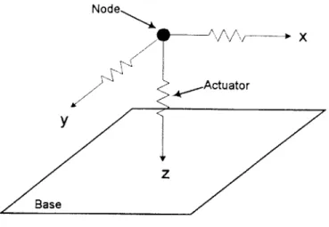
Figure 6. Tripod arrangement. 13
Figure 7. Actuator stroke usage. 13
Figure 8. Hypothetical trajectory of horizontal motion. 15
Figure 9. Circular trajectory. 16
Figure 10. Rectangular trajectory geometry. 17
Figure 11. Trapezoidal trajectory. 18
Table 1. Minimum number of node sets N,n as afunction of desired functionality. 21
Figure 12. An active, instrumented coil spring. 26
Figure 13. Top level of surface wave actuator. 28
Figure 14. DC motor setup. 28
Figure 15. Cable connections. 29
Figure 16. Nodal connections. 29
Figure 18. A pneumatic surface wave actuator. 31
Figure 19. Current control circuit. 32
Figure 20. Pressure sensor linearization circuit. 33
Figure 21. Multiplexer circuit. 33
Figure 22. Estimation of deflection. 35
Figure 23. Petri net for node set coordination. 38
Figure 24. Overall control architecture including global body positionfeedback, discrete state feedback
and local actuator feedback. 41
Figure 25. Comparison between rectangular and trapezoidal trajectories, position. 46 Figure 26. Comparison between rectangular and trapezoidal trajectories, velocity. 47 Figure 27. Plots of node set motion & states. 48
Figure 28. Rotation of an object. 49
Figure 29. xy plot of centroid's trajectory. 50
Figure 30. Evaluation ofprediction/estimation ofposition algorithm, trapezoidal trajectory. 51
Figure 31. Patient transfer using SWA. 53
Introduction
Patient mobility is a growing concern for health care facilities in the United States. In nursing homes alone, there are 1.5 million bedridden patients [1]. These patients require assistance for even simple tasks, and must be turned every two hours to prevent decubitous ulcers, or bedsores, from forming. 25% of all patients in nursing homes will suffer from these painful sores [2]. Other patient handling tasks include transfer between wheelchairs and beds, transfer between wheelchairs and toilets, and changing the patient's clothing. According to one study, on average a nursing assistant must perform
50.8 such labor intensive tasks every eight hour shift [8].
In order to meet the needs of the patients, caregivers are forced to move the patients manually, a very labor intensive task. According to a survey by Garg, one out of two nursing assistants surveyed received treatment for back injuries in a three year period, and one out of three lost at least one work day [8]. In terms of Lost Work Day injuries, being a nursing home employee was the most dangerous service job in America in 1996, with 8.2 full time employees losing a day for every 100, on average [2]. Many of these injuries are to the back or shoulder; 1 in 22 nursing assistants lost a workday from a back or shoulder injury in 1994 [4]. These are only the injuries which are reported; surveys of nurses and nursing assistants have revealed a tendency for these personnel to put the needs of the patients before themselves. "Nurses come to work even if dead," said one nurse in an interview [10]. Surveys show that 66 to 75% of back injuries go unreported
[9,8]. These injuries result in a cost of $24 billion each year [11].
There have been efforts to train nursing assistants in the proper ways to lift and manipulate patients. However, one biomechanical analysis suggests that the stresses required to move patients manually will always be unsafe for nurses of average strength
[8,12]. Therefore, there is a need for mechanical devices to reduce these stresses. These
devices are arranged in three main categories: assistive devices, such as belts, slings, and draw-sheets; hoists; and other devices such as conveyors, turntables, and rollers [13]. Although many such devices are available, it has been determined that 98% of patient transfers are performed with manual techniques [8]. Many reasons are associated with this lack of use: insufficient training, danger to patients, uncomfortable for patients,
insufficient personnel to man the equipment, strength requirements, excessive transfer times, lack of space, and lack of equipment. Hoists, such as Hoyer, Trans-Aid, and Ambulift were avoided because psychogeriatric patients could cause the hoist to topple
[8]. In terms of transfer time, manual lifting operations typically require 18s, while setup
and use of a hoist requires about 120s. [13]. Garg's study also indicates that the use of hoists may, at least qualitatively, be as stressful as manual lifting techniques.
However, efforts are underway to develop better systems to increase patient mobility. To eliminate bed-wheelchair transfer, a hybrid bed/chair system, RHOMBUS, has been developed and tested [7]. Recently an active bed with a mechanical linkage mechanism succeeded in moving a human lying on the bed by creating a surface wave in one direction [6]. Despite these endeavors, aids for the bedridden that provide diverse functionality have not been developed. A perfect system could move the patient in two dimensions and move individual limbs separately, all while the patient lies comfortably within the plane of the bed.
The research conducted for this thesis was aimed at developing such a system. The following sections describe the solution that was developed, the Surface Wave Actuator. The functional requirements and design parameters of the system are discussed. The notation needed to describe the surface waves, and algorithms used to control them are introduced. The two proof of concept prototypes built at MIT are described, and experimental results obtained from them are evaluated.
Design Objectives
The objective of the our patient motion system is to assist caregivers in positioning and transporting bedridden patients. Accomplishing this objective requires that the following functional requirements be met:
1) The system must be comfortable and appropriate for long-term care, and must not
detract from the comfort of the patient while not in use. The system should be appropriate for home and hospital settings, to maximize applicability.
2) The whole patient body must be moved in an arbitrary direction on the bed surface without lifting the body from the surface. Arbitrary motion is desired so that the patient can be moved to any position, under any circumstances. If the bed is to be installed in homes, arrangements of bedrooms may vary considerably. Arbitrary motion includes rotation, which allows for the patient to be reoriented on the bed if necessary. The body is not to be lifted from the surface, as this has been found to be extremely unsettling to most patients [8].
3) The limbs of the patient must be moved individually while lying on the bed. This
allows for periodic therapeutic massage to occur to certain parts of the patient, without disturbing the main body.
4) The motion must be smooth, with minimal jerk and disturbance of the patient. Systems that are not comfortable to patients will not be used.
Design Concept
To meet the above requirements, we introduce the Surface Wave Actuator. This is a new type of active bed that provides both high mobility and sleep comfort. Actuators embedded in the mattress surface generate periodic surface movements that transfer the bedridden in an arbitrary direction. By actuating the bed itself, we can move the patient without removing them from the bed. By using many independent actuators, we can create localized surface waves, which move only selected parts of the body. Since the system is designed directly into the bed, comfort can be readily obtained.
Surface wave motion is accomplished by nodes, which are distributed across the surface. See Figure 1. A node is an element of the surface which contacts the body and supports it, yet is free to move in the horizontal directions. Each node can also move in the z direction to detach from the patient. The coordination of motion in the horizontal and vertical directions allows the node to form a rectangular or circular trajectory. At the top of the path, the node contacts the body and accelerates it in the desired direction. At the end of its stroke, the node retracts away from the body so that it can return to its starting position.
Direction of Object M otion Direction of Motion at Crest
Figure 1. Surface wave actuation of an object
Bed Surface
Figure 2.
Nodes
Nodes distributed on bed surface.
Figure 2 shows the layout of individual nodes across a two-dimensional bed surface. Notice that each node may move in five directions from its initial starting position; four horizontal displacements, and a vertical displacement. The nodes shown in Figure 2 are grouped into two or more sets, called node sets. All nodes in a set are in phase with one another in their periodic motion, and nodes in adjacent node sets are out of phase. The members of the set will be distributed evenly across the bed surface. In this manner some
nodes will always remain in contact with the body. See Figure 3. The number of node sets is designated by N.
Figure 3. Phase shift <} between nodes.
(a)
(b)
)--
--- - - - )
(d)
Figure 4. Periodic motions of nodes for motion in the +x direction.
Figure 4 shows the periodic motions needed to generate motion of a body in the +x direction. The nodes in this example are implemented as coil springs, as found in many commercial mattresses. First, one set of nodes (shown in solid lines) is moved in the +x
direction (a). Second, it is detached from the body (b), then moved in the -x direction to its starting position (c). Lastly the node set is reattached (d). If the second set of nodes (shown with dotted lines) moves 1800 out of phase with this motion, the body may be moved continually in the x direction. Combined with similar motions in the y direction we can generate body motion in arbitrary directions. Furthermore, changing the state of z-axis actuators in coordination with the horizontal axes can cause the body to rotate, or generates localized body motions, as will be addressed in later sections.
The terminology used above can be described mathematically using some simple notation. Each node is numbered 1 through n. The coordinates of the tip of the k node are denoted (xk, yk, zk), k = 1,..., n.
Each node is controlled in the z direction to take either a high or low position. In this analysis, we assume that the node is sufficiently stiff to support the body without significant deflection. Otherwise, the node would be unable to disconnect from the body
in its Z,0 position.
zk =Z : high position, attached to the body
Z1 :low position, detached from the body
The horizontal coordinates of the k node are varied from its unforced position, xk and yk, to a deflected position by the horizontal actuators driving the k node:
x k=x +Ax,
(2)
where Ax, and Ay, are deflections generated by the ih actuators of the x and y axes, respectively. As mentioned before, nodes are grouped together into node sets for horizontal movements, and are driven by several independent actuators. Let N be the number of node sets, and Si be the i* node set, 1<s i < N, containing all the node numbers, k, of the nodes moved simultaneously by the same horizontal actuators.
As mentioned before, nodes are grouped together for horizontal movements, and are driven by several independent actuators. A set of nodes moved simultaneously by the same horizontal actuator is referred to as a node set. Let N be the number of node sets,
and Si be the i node set, 1 i 5 N, containing all nodes driven by the i* actuators of both the x and y axes.
Si = {k
I
All nodes connected to the i horizontal actuators} (3)Note that two actuators are used for moving the nodes in Si in both the x and y axes. Note also that any actuator node sets Si and Sj are exclusive, and every node belongs to one and only one actuator node set.
Design Parameters and Equations
Requirements
Every surface wave actuator must satisfy certain minimum requirements in order to function correctly. The nodal path must be reciprocative, that is, can be repeated an infinite number of cycles. This allows the patient's body to be moved with respect to the bed, with no net motion of the bed surface. The nodes must be able to detach from the body, so that they can regain stroke for another cycle of patient movement, without affecting the patient's movement due to other nodes. The nodes must be divided into at least two independent node sets, each of which is controlled by at least two horizontal actuators per axis, and one vertical actuator. This allows the node sets to perform three degree of freedom motion, as is explained in section 5.
Physical Node Design
Actuator Arrangement
A critical issue regarding actuator design is the orientation of the actuators with respect to
the axes of motion. Two feasible possibilities have been explored in this research. The first possible arrangement are decoupled axes, as shown in Figure 3.
Node x Actuator y z Base
Figure 5. Decoupled axes.
Each direction of motion is controlled by one independent set of actuators. The advantage of this system is that motion in the principle directions is simple to control, and sensors mounted to the actuators will provide direct feedback of the appropriate direction. This arrangement is well suited to square node trajectories. There are several disadvantages to this configuration, however. The actuators will tend to interfere with each other in the horizontal directions. Because they must be located at the edges of the bed in order to have a stationary reference from which to pull, the actuators must be connected to the nodes with cables. These cables will overlap nodes lying in the same row or column of the matrix. Therefore, the cable attachment locations must be slightly offset between nodes of the same row or column. The cables must be placed below the plane of the surface, so they do not interfere with the z axis motion of other nodes. Another disadvantage is that if a passive force is used to support the body, which is a likely situation in cases of many dense actuators, each vertical actuator will be required to overcome that force to cause z axis motion.
Node
Actuator
z
Base
Figure 6. Tripod arrangement.
In this arrangement, the actuators must cooperate in order to generate motion in the horizontal or vertical directions. There are several important advantages to this design. Actuator interference is reduced, allowing higher node density. All three actuators cooperate to produce z-axis motions, reducing the size requirements of the actuators. There are also several disadvantages. The control of the system is more difficult, as the actuators must be well coordinated for planar motion to occur. Accurate sensing of the stroke of the actuators is required. Also, the range of output motion will be reduced, since the actuators are at angles with the directions of motion. See Figure 5.
/x
sin
0
t
+-Sx
cos
0
0
Figure 7. Actuator stroke usage.
This arrangement is well suited for circular trajectories, since motion in the vertical and horizontal directions are coupled for them.
Actuator Properties
A surface wave actuator contains many nodes, each of which may contain several
independent actuators. Since these nodes are packed closely together, they must occupy a small space. As they are cooperating to move a heavy object, they must be able to exert a considerable in the horizontal directions, and either support the human actively when connected, or overcome passive support of the human body when disconnecting. Combined with our first requirement, this implies that a high power density is desired. Lastly, the actuators must have sufficient stroke to detach the node from the body. The exact amount of this stroke depends on the compliance of the body, and the spacing and phase difference between adjacent nodes. In order to ensure proper coordination of the nodal trajectory, the nodes should also have good positioning capabilities in the horizontal directions, and repeatable vertical actuation, although feedback is not needed. Randomly distributed vertical actuation velocities leads to improper disconnections and reconnections, and will cause the system to fail.
Nodal Trajectory Design
As mentioned previously, the key to surface wave motion is the action of the nodes distributed on the bed surface. Many possibilities exist for the path which these nodes follow. This section of the thesis will discuss how an effective trajectory was developed.
Fixed versus Flexible Trajectories
A trajectory may be implemented either as a rigid path, which the node will follow
regardless of other nodes or the body, or it may be adaptive, in that it coordinates its motion with the nodes adjacent to it and according to loads placed on it by the body.
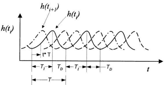
A fixed trajectory can be plotted as a mathematical function versus time, such as in
Figure 8. The position of the node is only dependent on time. Each node is represented
by a function h, which represents its horizontal position, and z, which represents its vertical position. The functions are monotonically increasing for the period of T, and monotonically decreasing for the period of TD. The N functions are out of phase, with
and z functions. If a z function is derived, such that the node set is in contact with the body during the period T, and detached from the body during the period TD, then motion of the body will result.
h(t +)
h(t)
h~t,)
t*T
T T T TD
T
Figure 8. Hypothetical trajectory of horizontal motion.
Fixed trajectory motion is demonstrative of the surface wave concept, and is the actuation method of choice for a system with a very dense set of actuators. In this case, system complexity is large, and a fixed trajectory may allow for open loop command of trajectory motion.
However, for systems with very discrete nodes, this manner of control would be ineffective. The motion of the nodes needs to be actively coordinated to ensure that the body is translated successfully, despite uncertainties from actuators or the effects of the environment and the load, the human body. These are referred to as flexible trajectories, and some possible choices are described below.
Choices for Nodal Trajectory
Any two-dimensional geometry could be implemented as a surface wave nodal trajectory, but only those satisfying the requirements listed at the start of this chapter will be effective. The trajectories which were investigated during this research are described below.
Circular
Figure 9 shows a circular trajectory in a vertical plane. Without loss of generality, we assume the plane of the trajectory is parallel to the x axis. The periodic function h(t) introduced in section 3.2 is simply the projection of this circular trajectory onto the horizontal plane. Namely, h(t) = R sin(cotd.
X
Z
x
Figure 9. Circular trajectory.
This trajectory is similar to the motion caused by natural waves observed on the surface of bodies of water. In these waves, water molecules travel through circular trajectories. The circular trajectory is fairly smooth during horizontal motions, as long as the number of node sets N is large and the phase difference between adjacent node sets is small. However, as N becomes smaller, there is an undesirable z-axis motion created by the transfer of weight from one set of nodes to another. The total magnitude of this motion is dependent on the phase difference between the nodes and the radius of the trajectory, as given by:
AZ = R( - cos(A 2 / (4)
where A# is the phase lag between adjacent nodes, and R is the radius of the trajectory. The circular trajectory can be created by mechanical linkages, such as a piston and crank mechanism, and was used for the surface wave actuator [6].
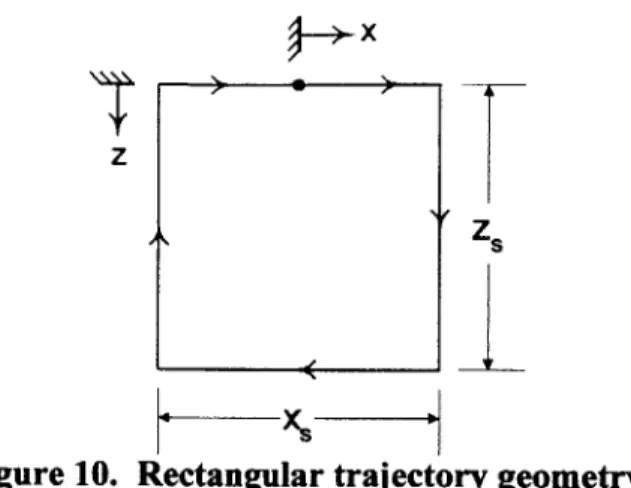
Rectangular
x
T
Zs
Figure 10. Rectangular trajectory geometry.
To eliminate this unwanted vertical perturbation, we can employ a rectangular trajectory, as shown in Figure 10. This trajectory causes no vertical perturbation, since the path in contact with the body is a straight line. Another advantage to this trajectory is its simplicity. It can easily be implemented with a bed system with decoupled arrangement of actuator axes. Also, with two node sets at 180 degrees of phase difference, the nodes are always travelling in opposite directions with this trajectory, so only one actuator per axis is needed. The node sets would be geared so that they move in opposite directions. The simplicity of this trajectory allows it to perform complex maneuvers that might otherwise require many actuators per axis. See Table 1.
The disadvantage of this trajectory is that at the end of each horizontal motion the node must come to a stop, and wait for the adjacent node to complete its motion. Also, at the end of each vertical motion the node must be accelerated quickly, inevitably causing jerky motion. Therefore this trajectory violates our fourth functional requirement.
Trapezoidal
To overcome the limitations of the previous trajectories, a hybrid trajectory has been designed. This trajectory has the benefits of zero vertical perturbation of the body, due to the straight line body contact path, combined with smooth horizontal motion. The horizontal motion is smooth since before the node makes contact with the body, it has obtained the velocity of the body; therefore, the body need not come to a stop for reconnection to occur. The same occurs during disconnection, but in reverse; the node
disconnects, and then begins to change its horizontal velocity. This section describes the expressions needed to create coordinated motion using this trajectory.
r
X MoveFwd FwdEndZone z xXS _Xcon 5 R 2 4 3 BwdEndZone MoveBwdFigure 11. Trapezoidal trajectory.
Let vfrd be the horizontal velocity of each node set moving forward (from point (5) to (2)
in Figure 11), and vbo the velocity moving backward (from point (2) to (5) ). While
moving backwards, the nodes do not support the body. Therefore increasing the backward velocity vboJ reduces the duration when the nodes are not in contact with the body. Reducing this non-contact period means that more node sets may be supporting the body. This results in higher stability and comfort for the patient. Let obtain conditions on the velocities vpj and vbd so that only KdW node sets are in time-average
disconnected from the body, and (N - d) node sets are supporting the body during the transfer process.
Let x, be the horizontal stroke of each node, as shown in Figure 11. Assuming instantaneous horizontal accelerations, we can derive the following equation for the period of the trajectory:
T- + Xs (5)
The time spent by each node set when disconnected or being disconnected from the body is given by
T XS -~XB XS
Td, - + (6)
V'fW Vb-K
In time average, the fraction of T,, to T agrees with the fraction of the number of disconnected node sets Nd,, to the total number of node sets N.
Tdis _ dis (7)
T N
Substituting equations (5) and (6) into equation (7) yields:
vN - Nd.,
(8)
vM Ndi,+ N(b -1) where b is the stroke usage fraction:
b
= Xc"" (9)xs
Note that in order to reduce the average number of disconnected node sets, the ratio of backward velocity vbd to forward velocity vjw must be increased. Note also that although the number of node sets is small, the body can be continuously supported by many node sets, as much as N - 1, if the backward velocity is much faster than the
forward velocity.
System Design
Design Parameters
Many parameters need to be considered in the design of the system as a whole. The number of nodes used, the number of actuators per axis, and the manner of feedback signals to be obtained need to be considered at this level of design.
The number of nodes in the bed is an important design consideration. It is a function of the area of the bed and the density of nodes within it. The density of the nodes is limited
by the size of the actuators, and their arrangement.
The preload needed in each node is a function of the number of nodes in the bed. This force is defined as the minimum force needed per node to support the densest weight that the bed might carry. It is given by the following relationship:
F= WAb (10)
Aonfhigh
where F is the preload, W is the weight of the load, Ab is the area of the entire bed, Ao is the area of the projection of the object onto the bed, and ~high is the average number of nodes in the high position on the bed surface during body transfer. Clearly, the higher the ratio of Ab to n, the less preload is required in each spring. Another parameter affected by the number of nodes is the maximum allowable horizontal stroke. If we assume that the nodes are evenly distributed on the bed surface, then the maximum stroke xm, will be:
x.= = (11)
n
Another design parameter to consider is the number of actuators to use. For a tripod arrangement, at least three actuators are necessary per node to obtain two-dimensional surface wave motion. More actuators would be redundant. Three actuators per node are sufficient to perform all possible motions; since every node is independent from all others, they can be grouped into any number of node sets.
For a decoupled arrangement, the horizontal actuators typically control a fixed node set, without overlap. That is, every x axis actuator is paired with a y axis actuator, and is connected to n/N nodes. The z axis for each node can be independently controlled, or the z axis for all the nodes in a node set may be linked together. Table 1 lists the minimum number of horizontal actuators per axis needed to perform various modes of motion. (The modes of motion are described in detail in the next section.) Note that the number of actuators per axis corresponds to the number of node sets, N. These minimums were calculated using the following general guidelines. First, intermittent linear translation,
which is produced by the square trajectory, requires only one actuator per axis since the other node set can be merely placed by hardware to be out of phase by 180 degrees. Smooth motion, as produced by the trapezoidal trajectory, requires two actuators per axis, since they must move at different velocities. Localized motion requires one more node set than the equivalent whole body motion; this node set merely remains stationary. Independent z axis actuators are required to detach stationary nodes from the moving body. Intermittent rotation or divergent motion is possible with only one actuator per axis, provided independent z axis actuators are available. The z actuators effectively set the horizontal motions out of phase, so that actuators which are disconnected on one side moving forward are connected on the other side of the body. Smooth rotation or divergent motion requires four node sets, since each direction of movement requires a pair of actuators working in coordination, and two directions are needed simultaneously.
Functionality
Ni IndependentZ?
Intermittent Translation 1 no
Intermittent Rotation/Divergent Translation 1 yes
Smooth Translation 2 no
Smooth Rotation 4 yes
Intermittent Localized Translation 2 yes
Smooth Localized Translation 3 yes
Smooth Localized Rotation 5 yes
Table 1. Minimum number of node sets N,,,m,, as a function of desired functionality.
Control Modes
Once the number of nodes and actuators has been determined, the control modes for two dimensional surface wave motion which are feasible for the design can be ascertained. These control modes are described below.
Whole Body Translation
In this case we wish to move a body horizontally in the direction of angle 0 from the x axis. The node sets are coordinated such that:
Ax, = h(t,)cos0 (12)
Ay, =h(ti)sin9 (13)
where h(t) is a periodic continuous function of time ti that generates a reciprocative motion in the horizontal direction. An example was given in Figure 8. All node sets move along the same trajectory, and therefore use the same function h, but have different phase angles. The time ti is given by:
= t + T -i (14)
2;r
where Tis the period of the function h, and
#, is the phase difference between node sets i
and i-1. The node sets will typically be equally spaced in phase:# = 1,i 1,..,N (15)
N
Figure 8 illustrates a group of hypothetical functions, h(t), h(t2), ... h(tN). The functions
are monotonically increasing for the period of T and monotonically decreasing for the period of TD. The N functions are out of phase, with 2n/N of phase difference between them. The vertical motion of each node is synchronized with the horizontal motion so that the node is attached to the body only when the function h(t) is increasing. (i.e., the period T1 shown in Figure 6.) In this way only forward motion is transmitted to the body.
If the k node belongs to the id node set, the z axis of this node is commanded to take the
ZT Zhigh' T Z' low' o Thf i (16) Z1,; otherwise where ' T 2r (17)
Note that the operator [e] takes on a value between 0 and 1, and ti* represents a time index, normalized by period T and shifted by phase angle *i/2n. Nodes in the i* node set move forward for 0< ti* < T1/T, and the z axis is at Zhish during this period, so that the
node is attached to the human body and transmits horizontal motion to the body.
The above control scheme requires all the z axis actuators to be moved, but those actuators that are not under the human body need not be activated. To save energy they should be kept inactive. This control mode provides a general scheme for coordinating horizontal and vertical movements in order to transfer a body by reciprocative motion. Detailed control issues will be addressed in the following sections.
Local Movements
This control mode allows one or more segments of the body to be moved across the bed surface, while other parts remain stationary. To accomplish this, at least one node set is moved in the same way as in the Whole Body Translation described above, while the remaining node sets are kept stationary in the horizontal direction, so that the body is supported from beneath at all times and the rest of the body is held stationary. To combine these two functional requirements in a non-conflicting manner, the z coordinate of each node is controlled such that:
. Nodes are detached from the body if they are moving horizontally and are beneath the part of the body to be held stationary,
. Nodes are attached to the body if they are moving forward and are beneath the part of the body to be transferred,
- Nodes are detached from the body if they are moving backward in the horizontal direction, and
- Nodes that are kept stationary in the horizontal directions are attached to the body if the nodes are beneath the part of the body to be held stationary, or if there is no other node set supporting the part of the body to be moved (i.e., in the case of two node
sets, when one node set is moving backwards, the other must support the body.) Let us define a set SA as all nodes under the part of the body to be moved, and SB as all nodes under the part of the body to remain stationary. Let us assume that node sets Si, i = 1,..., Nm, move both horizontally and vertically as described in Whole Body Translation. The remaining node sets, Si, i = N,,+1, ..., N, remain stationary in the horizontal
direction. We then obtain the following expressions for this control mode: Fork e S,, 1 i NM: Ax, = h(t,)cosO Ay, = h(t,)sin0 Zhigh if k E S A and 0 t < ~'T) z k(t)) ZIOW if (ke SB) or (k e SA and Lt 1 For keS, N, +1 s i s N: Ax = Ay, =0 Z,gh; if (kCE SB)or (k E Sand zi Vj E S, u...u z k(t)= Z,0,; if (k e SA and 3j e S, u...u such that z = Ziow SN) SN. Zh,,h) (19) (18)
In general, this requires at least one additional set of nodes than is required to perform a given motion; this node set or sets remains stationary with respect to the x and y directions, and its nodes stay in contact with the stationary portion of the body, while the remaining nodes are detached from the moving portion of the body. In the special case of
N = 2, the stationary node set is required to periodically support the body, while the single moving node set is detached from the body. Note that those nodes which are not under the body (i.e., k e SA U SB) should remain inactive in order to conserve energy.
Divergent Translation of Two Body Segments
By modifying the above local movement control mode, two segments of the body can be
moved in two opposite directions, such as the legs opened or closed. Assume that body segments A and B are to be moved in opposite directions to each other. The z axis motion of the nodes beneath A, k e SA, and the ones beneath B, k e SB, are set 180 degrees out of phase so that forward motion alone may be transmitted to body A while only motion in the opposite direction is transmitted to B.
Fork ESA: T, zkZ(t) ,; 0=1 t* < T ST -, Z,"; T, < t, <1i .T (20) For k E SB:
fT
Zj""; 0: * t <, z k(t) = Zto, T high T -tTo keep the remaining part of the body stationary, i.e., the body segments other than A and B, the above control mode must be augmented by combining the local movement control mode given by equations (18) and (19). To save energy, those z axis actuators under the human body alone should be activated. A special case of this algorithm allows us to rotate the entire body: the Whole Body Rotation mode. This is done by creating two anti-parallel velocities, symmetric to and at equal distances from the center of mass of the body, perpendicular to its longitudinal axis.
Implementation
This section discusses the design of the various systems which make up the two surface wave prototypes. The decisions made in the selection of components and the interconnections between the subsystems will also be discussed.
Mechanisms
Surface Wave Actuator 2
Preload Unsprung position of ' - - retaining plate Pressure
Sensor
zFigure 12. An active, instrumented coil spring.
Surface wave 2 is a functional mockup table with 32 nodes. Each node consists of a spring extracted from a commercially available mattress, which allows us to meet our first functional requirement (see Section 2). Figure 12 shows the components of a typical
node. An SMA actuator attached to it supplies motion in the Z-direction (orthogonal to the plane of the patient), while X and Y motion is supplied using DC servo motors. Each spring initially is compressed by tension in the SMA fiber in the z-direction. One of the fundamental requirements for the active mattress is to support the patient body at all times, even while some springs are detached. Therefore, the springs in the high position must be able to bear the load of the body, without deflecting so much that the other springs in the lower position cannot be detached. To prevent excessive deflection, the coil springs are given a preload, as shown in Figure 12. Each spring can then support a weight up to the preload before any deflection occurs. In this prototype, the preload was adjusted by changing the length of the cable strung between the top plate and the shape memory fiber. The shape memory fiber was chosen because it meets many of the requirements for providing z axis motion discussed in the Node Design section. It has a high power density, able to pull nearly 20N while being only 0.2mm thick. It occupies very little space. However, its stroke is limited, so careful selection of the preload has to be made to ensure that excessive deflection does not occur.
As shown in Figure 13, the top of each node is equipped with a pressure sensor. Each pressure sensor is a small disk about 25.4mm in diameter and 0.635mm thick. To achieve proper activation of the pressure sensors when a weight is placed on the surface, a rubber anvil is mounted to the center of each pressure sensor. This ensures that weight is carried by the sensor before the rest of the node surface so accurate measurements can be made.
As can be seen from Figures 14 and 8, the x and y axis motion is provided by four DC motors, each connected to an axis and four pulleys. (The y axis motors were not installed at the time of this photo.) Two motors are needed to provide motion in opposite directions at different speeds, facilitating the trapezoidal trajectory. A cable, connected to four nodes, is wound around each pulley. Thus, each node set is connected to two motors, one for each axis of motion.
ty
CableCoil Spring
Driven by Actuator:
Ty2
Figure 15. Cable connections.
DC motors were used because the horizontal motion needs higher accuracy and faster
speed of response than that of the z axis. As illustrated in Figure 16, the individual coil springs need not be moved independently. The set of all springs can be divided into several subsets and actuated together, in order to generate periodic motions for transferring the body, as was discussed in the System Design section. Figure 15 depicts the configuration of cables connecting individual springs to servo motors. Every second row of coil springs is connected by cables and thereby moved together with the same actuator, yielding displacement Axi, while the remaining nodes are moved by a second actuator an amount Ax2. Likewise, two actuators in the y direction provide displacements
Ay1 and Ay2, respectively, for columns of coil springs.
it* node set (Driven by i actuator.) cable xk Zhigh ZIOW k" node
Figure 17 illustrates the layout of the SWA 2 prototype design. The table consists of three shelves. The upper shelf is used to support the coil springs and their payload. The central shelf serves as an attachment point for the SMA fibers, and the circuit boards will be mounted here. The space between the upper and central shelves is strung with the
SMA Disks Pulley Rod Coil Springs
Figure 17. Bed prototype.
shape memory alloy wires, and cooled with forced convection provided by a fan. The cables for horizontal motion first run over pulleys attached to rods which flank the upper shelf. The cables then run through the upper shelf, and attach to the retaining plates mounted to the springs. The lower shelf supports the power supply which provides current to the SMA alloys.
Surface Wave Actuator 3
After surface wave 2 was constructed, it was determined that a system built with pneumatic actuators would provide higher system bandwidth, and therefore act as a testbed for algorithm development. The algorithms can be run at high speed to test their stability and robustness, and then transferred to surface wave 2 for final testing.
c surface wave actuator.
Surface wave 3 consists of forty pneumatic cylinders, four AC servo motors, and sixty-four pressure sensors. See Figure 18. The cylinders are arranged in eight columns of five each, with the columns parallel with the y axis. Four linkages connect pairs of the five cylinders in the column. Every other column is attached to the same runner, which is in turn connected to the nut on a lead screw, driven by an AC servo motor. On the surface of the bed at both ends of each linkage is a pressure sensor. Like SWA 2, a rubber anvil is used to transmit force from the object to the sensors.
Electronics
A considerable amount of interface hardware is needed by the PCs that control the
Surface Wave Actuators. Surface Wave 2 uses two A/D boards that provide a total of 32 channels of A/D for the 32 pressure sensors, 4 digital input ports to read the status of the home switches, and 4 channels of D/A to control motor currents. It uses a 4 channel encoder board to read the position of the 4 motors. Lastly, it uses two D/A boards to control currents through the shape memory alloys. This voltage signal is fed into the circuit shown in Figure 19. This closed loop op-amp configuration provides a current proportional to the voltage applied.
40V
SMA
D/A+
0.10
Figure 19. Current control circuit.
Another op-amp is used to obtain a linear voltage measurement of the resistance passed through the pressure sensors. See Figure 20. The force sensing resistor is placed in a voltage ladder with a 10k ohm resistor. The voltage is then supplied to an op amp in a unity gain buffer arrangement, so as to guarantee that the correct voltage will be read despite loading from circuits attached to the output of the op amp.
Vcc
A/D
1
Figure 20. Pressure sensor linearization circuit.
Surface Wave 3 needs only one A/D board, an encoder board and one DIO board. Eight channels of A/D are used to read 64 pressure sensors, through the use of an 8 channel multiplexer. The pressure sensors are connected in a matrix, so that one terminal of each sensor in a row is connected to one terminal of each sensor of that row, and the other terminal is connected to one terminal of each of the sensors in the column. The rows are then multiplexed to the +5V power, and the columns are connected to independent linearization circuits, which were depicted in Figure 20. When a row of sensors is to be read, the digital output is selected so that power is given to that row, and then A/D conversions are made. Since the other sensors are in an open circuit, they will not affect the results of the measurement. The process is repeated for each row in the matrix, until all sensors are read. The multiplexer circuit is shown below. Note that three channels of digital output are needed to control the multiplexer.
Vcc Multiplexer To Pressure S8 Sensors INH C3 C2 C1 - 0 0 0 a 0
Two more digital outputs are used to control the z-axis of the two node sets. As described in the Mechanisms section, each node set consists of 20 pneumatic cylinders, and all are toggled via one binary pneumatic valve. The last hardware requirement is that four digital inputs are needed to read the DC motor home switches.
Control
A distinct hierarchy of control exists in the implementation of the surface wave actuators
that has been created for this research. We begin by describing the choices made regarding nodal control, as in the algorithms and trajectories used. Next, coordination between the node sets is discussed, and how it allows smooth motion to occur. Lastly, the thesis introduces the Global State Feedback architecture, and the manner in which user commands result in proper trajectory formulation.
Nodal Control
During the development of the SWA 2 prototype, the selection of the trajectory to be used to formulate the surface wave motion was of considerable importance. The system had to be designed to allow for the trajectory to be successfully implemented. The purpose of the prototype was two-fold, however; to demonstrate the feasibility of surface waves, and to test the use of shape memory alloys as an actuator. It was quickly realized during the design phase that creating a tripod arrangement of actuators would be prohibitively complex at this stage of the project. Also, the tripod arrangement works best for the circular trajectory, but since we were to make use of SMA fiber actuators, this trajectory would have been highly distorted without external feedback, which would add more complexity to the system.
Instead, the decoupled axes approach was taken, as was described in earlier sections. This then made the already undesirable circular trajectory very difficult to produce, leaving us with the square and trapezoidal trajectories. The problem of jerky motion inherent in the square trajectory meant that it too would be unable to satisfy our functional requirements of smooth motion. We therefore adopted the trapezoidal trajectory, and designed the system such that it was capable of producing it.
However, the problem remains that the z-axis does not have direct position feedback. Therefore, careful management of current is required to ensure that the node reconnects at the proper time. The node in a set must reconnect simultaneously for efficient operation. To this end, a calibration current is used to keep the nodes which cool and contract quickly slightly warm, slowing their contraction until it equals the slowest node. This current is determined experimentally.
Once all of the nodes in the set have detached, the set begins to return to the beginning to start another contact run. The z-axis continues to contract for a set amount of time, and then is allowed to cool. The amount of time required for cooling is dependant on the load placed on the body supporting nodes. A high load on the nearby nodes means that the springs are deflected, and therefore the node will contact the body sooner. The node must be moving at the velocity of the body before it touches it, or there will undesirable shear forces created. If the node begins moving prematurely, some horizontal stroke will be wasted, reducing system speed. The load on the nodes in contact is determined by the pressure sensors, and an estimate of the load above the node is interpolated from that data. See Figure 22.
F.,
F.1
i1
P
P
i-I i +1
Figure 22. Estimation of deflection.
Here we are considering the it node. The i- 1 and i+l nodes are both out of of phase with the i*h node by 180 degrees. They are in contact with the mass, which exerts a force Fi.1
and Fi+1 respectively on the nodes. This is balanced by the force in the spring. To keep
is approximately identical for all nodes. Some force is used to overcome this pre-load, and the remainder of the force compresses the spring. The resulting expression for &xi, the estimated displacement of the ih node, is then:
&i_1 +&dial Fi_ i - 2P
&, = =+& + FI (21)
2 2K
This value may be used with a model for the strain of the SMA fibers as they cool to determine the approximate time the node will contact the body.
Coordination Control
The trapezoidal trajectory has unique features which allow smooth, stable movements. To achieve these movements, however, all actuator motions must be well coordinated. Not only must the vertical actuators be coordinated with the horizontal actuators, but the node set as a whole must be coordinated with other node sets. Standard fixed trajectory controls do not apply to this system, since discrete contact/non-contact states must be controlled during the process. Sensors are needed for detecting contact and non-contact between each node and the patient body. Occurrence of connection and disconnection cannot be predicted precisely due to the unpredictable nature of the z-axis shape memory alloy and the uneven surface of the human body. As mentioned in Section 2.2, pressure sensors attached to the top plates of active springs are used for detecting contacts with the patient body in order to synchronize the multiple axes and node sets. This synchronization is based on occurrence of events rather than time, hence the system is treated as a discrete-event control system.
In this section a discrete event controller using a Petri net is developed. Petri nets are powerful tools for describing concurrent discrete-event systems containing many subsystems which are independent but are synchronized with other subsystems based on discrete events [3]. The active mattress developed in this paper consists of many subsystems, termed nodes, which are grouped together as a node set. Furthermore each node consists of horizontal and vertical axes that are controlled by different actuators. It is inconvenient to model this system as a standard finite state machine, since combining subsystems into one large finite state machine incurs complicated problems, including
redefinition of states. In Petri nets, states are defined independently for individual subsystems rather than for the whole combined system, and interactions among the subsystems are represented explicitly and effectively.
Figure 23 shows a Petri net representation for discrete-event control of the active mattress system having two independent node sets. For simplicity, only the x-axis is shown and the y-axis is eliminated in the figures. All the discrete states, along with input and output symbols, are represented by circles, termed places, and transitions among the places are shown by arcs and bars, following the standard Petri net convention. Transitions have been lettered a through n for the subsystem for node set 1 and others.
The lower part of the Petri net contains the horizontal and vertical axes subsystems comprising the following states:
Horizontal axes: MoveFwd FwdEndZone MoveBwd BwdEndZone AllCon MoveLow AllDiscon
Moving forward, from point (5) to point (1) in Figure 11 End zone of forward motion, from (1) to (2)
Moving backward, from (2) to (4)
End zone of backward motion, from (4) to (5) Vertical axes:
All the nodes in the same node set are at Zhigh and connected to the body
Moving towards the Ziow position
All the nodes in the same node set are at Ziow and disconnected from the body
Moving towards the Zigh position MoveHigh
C
Node Set
1
Node Set 2
Figure 23. Petri net for node set coordination.
The left half of the network in the figure represents the first node set; the right half is the second node set. There are two cyclic loops involved in each node set; the outer loop, MoveFwd-FwdEndZone-MoveBwd-BwdEndZone, represents the horizontal motion, while the inner loop represents the vertical motion. These two loops are synchronized at specific transitions. For example, at transition d in the network, horizontal motion is reversed from forward to backward after AllDiscon has been achieved, i.e. all the nodes have been disconnected from the body. This is to prevent the body from being pushed backwards by the nodes returning to the original horizontal position. The arc from
AllDiscon to this transition bar d requires the place AllDiscon to possess a token. Likewise transition e is prohibited unless the nodes in the first node set have arrived at FwdEndZone and all the nodes in the second node set have been reconnected to the body, as indicated by a token at AllCon in the right half network. This set of conditions assures that the patient body is supported all the time as the supporting nodes are changed from the first to the second node sets. Transition g is fired when the horizontal axis arrives at the end zone of the backward motion, i.e. BwdEndZone, and all the nodes have been disconnected. Then the vertical actuators begin to move upwards. After transition g fires, transition b is enabled, which changes the direction of the horizontal motion. This is to allow these nodes to gain the same speed as the patient body before reconnections occur. In addition to this basic coordination control, startup and termination procedures must be added to the Petri net. Since this active mattress system exhibits cyclic movements for both horizontal and vertical axes, the process cannot be stopped at an arbitrary state. Before stopping, the process must come to the state where both node sets are at the Zigh position, supporting the body, and the horizontal axes are in the middle or home position. To start the cyclic process, the two node sets must be brought to opposite states with 180 degrees of phase difference. The upper part of Figure 23 represents these procedures, which use the following additional states and inputs:
Init Input for initiating the cyclic process
Term Input for terminating the cycle
Run System is running
Stop Terminating the cycle and coming to the home state
Hold Temporarily holding the cycle
To initiate the process, a token is placed at Init. Under normal conditions, this controller holds the process by placing tokens at both AllCon and Hold in both node sets, as shown
by dots in the figure. Having a new token at Init enables transition i to fire. This
transition moves a token to Run, removes another token from AllCon in the second node set, and delivers it to MoveLow. This allows all the nodes of the second node set to be disconnected from the body and allows the transition
j
to fire, which enables the firstnode set to move forward. The cyclic movements of the two node sets then begin. To terminate this cyclic process, the token placed at Run is moved to Stop by firing transition n with an input signal placed at Term. Having a token at Stop enables either transition m and I to fire, when the horizontal axis in each node set arrives at MoveFwd. This removes the token from MoveFwd and places it in Hold. This terminates the cyclic movement of the horizontal axis. The vertical axis keeps moving until the AllCon place is reached, but is prohibited to shift to MoveLow, since FwdEndZone of the horizontal axis is no longer reached. Therefore, both node sets are brought to the home state, i.e. the Hold and AllCon states, and stopped there. The actual system includes several other states for switching between forward and backward motion and changing the direction of the motion. These states and associated transitions can be added to the above Petri net in the same way as the initiation and termination procedures. It should be noted, however, that these states act as an interface, connecting the discrete-event controller to a higher level controller that observes the human body being transferred, and generates a reference command. Based on this reference, the node set movements are switched.
Note that all of the subsystems involved in this Petri net are strictly conservative, in that the number of tokens in each subsystem is not changed by the firing of transitions. The subsystem of vertical axes, which consists of four places, contains only one token at all times. The horizontal subsystem consisting of four places plus the Hold place contains only one token as well. This can be determined by inspection, since the number of arcs into each transition equals the number of arcs out of that transition. Strictly conservative is an important property, as it allows the system to represent our discrete state framework accurately. Since the state of every subsystem is represented by a token, the state of the subsystem would be undefined if a token were to be lost. Subsystem conservation can be evaluated by counting the number of arcs which lead from places to transitions outside the subsystem. If the number of input arcs does not equal the number of output arcs, the subsystem is not conservative. Since the subsystems are conservative and only contain one token each, they are safe. Every place in a safe subsystem contains either 1 or 0 tokens. Since the subsystems are safe and distinct, meaning tokens do not pass into other subsystems, the entire net is safe.
Another important condition to evaluate is deadlock. This scenario occurs whenever no transitions are enabled to fire. The systems shown above will not reach deadlock for the
initial marking specified earlier.
Control Hierarchy
Gloal0 Body Poetion Feedk
Diet S t Feedback
Cumt Feebmd
Current Z-axis
Desired Discrete Control SMA Actuators Body Body -- Event y --- Location
Position Controller + ~ Position XY-axis Estimator Control Servo Motors
Loca ActuAor Feacack
Figure 24. Overall control architecture including global body position feedback, discrete state feedback and local actuator feedback.
Figure 24 shows the overall control architecture of the active mattress control system. Three distinct levels of control exist in the system. The lowest feedback loop is the control of individual actuators; position control of the xy axis servo motors and current control of the z axis SMA actuators. These loops are in turn fed commands from the discrete-event controller, which coordinates the actuators based on pressure measured at each node. This is dependent on the trajectory used; see the trajectory design section for more details.
The highest level control loop shown in the figure is the feedback control of the global body position. Based on the pressure distribution across the bed surface, the mass centroid of the human body is estimated. Several techniques have been developed for body posture and location estimation [14, 15]. We apply these techniques for estimating the body position, and close the feedback loop with respect to the patient's position. This allows the user to command the active mattress system at the patient position level, rather than commanding individual nodes and actuators.
The estimation technique used in the prototype is based on the existing human posture and position monitoring techniques, but is devised to meet specific requirements for the active mattress system. Like the existing techniques, the body centroid position is