Mechanical behavior of laminated
composites with circular holes
Achache Habib
1, a, Boutabout Benali
1, b, Ouinas Djamel
2, c1
Mechanical Physical of Material laboratory, University of Sidi Bel Abbes Algérie
2
University of Mostaganem Algérie
a
achachehabib@yahoo.fr, bbboutabout@yahoo.fr, cdouinas@courrier.com
Keywords: Notches, Stress Concentration Factor, Finite Element Method, Fibers Orientation, Laminates.
Abstract. This paper presents a numerical method for the evaluation of the stress concentration factor (SCF) in three dimensional laminated composites under mechanical loads. The proposed method uses the finite element formulation. The composites materials based on the epoxy matrix and reinforcing fibers are extensively used in aircraft structures due to their high specific characteristics. However, the withstanding of composite structures can be significantly reduced by the addition of geometric singularities, such as perforations or notches. To Analyses the stress concentration around geometrical notches, several studies as analytical, numerical and experimental techniques are available. The stress distribution in a laminated composite plate with the presence of a circular hole was investigated using the finite element method. In order, the results obtained by this study are compared with those reported in literature. The aim of this analysis is to evaluate numerically the factor of stress concentration under the influence of several parameters such as fibers orientation, the mechanical characteristics of composites and the distance between notches of cross-laminated.
Introduction
To achieve ever greater mechanical performance, innovative materials continue develop. Among them, composites are very successful in the industry and especially in the aerospace, laminated composites with long fibers play an integral role. This responds to environmental and economic imperatives that require the reduction of fuel consumption. On the other hand the increasing dimensions in aviation require the use of composite technology. These materials are assembled by drilling and riveting and / or bolting, and hundreds of thousands of rivets or bolts are required for the assembly of an airplane. The withstanding of these assemblies depends strongly on the quality of drilled accommodation holes and their positions. The asymmetry of the assembly generates important stress concentrations along the thickness. This phenomenon of stress concentration locally increases the stresses in an area with a geometric modification of the part. The zone of stress concentration is often the site of initiation of fatigue cracks but it can also cause a sharp break in the case of a brittle material. This requires knowledge of the variation of stress concentration factor (SCF) for the design of aircraft structures. Paul et al. [1] presented a higher order theory of shear deformation of a laminate sheet having two elliptical holes under a bending load. Younis [2] developed a systematic study using the experimental method of photo-elasticity by determining the effect of the equivalent stress around a multiple of circular holes under monotonous stresses. Xiwu et al. [3] studied the stress concentration around elliptical holes of a finished laminate using a method of Faber series expansion. Paul et al. [4] presented a theory to evaluate the stress concentration factor in a thick laminated plate using the theory of bending under transverse loading. Ting et al. [5] proposed an analytical method to analysis the stress distribution around multiple circular holes. Tubal et al. [6] studied experimentally the stress concentrations in a circular hole in a composite plate. Mahiou and Bekaou [7] studied the concentration of local stresses and the prediction of tensile failure in unidirectional composites. For plates pierced with a circular hole
All rights reserved. No part of contents of this paper may be reproduced or transmitted in any form or by any means without the written permission of Trans Tech Publications, www.ttp.net. (ID: 128.210.126.199, Purdue University Libraries, West Lafayette, USA-03/06/15,03:08:34)
subject to a state of traction in the x direction, it is known that occurs around the hole an increase in the value of the stress which is characterized by the coefficient of stress concentration Kt (ratio between the value of the maximum stress and the value of the stress far away from the hole). This coefficient is 3 for an isotropic material. Our work aims at the analysis by the finite element method
of the evolution of the parameter Kt of three 100x100 mm2 plates made of the same epoxy matrix
and different reinforcing fibers (graphite, boron and glass), whose mechanical characteristics of laminated composites are shown in Table 1 dimensions, under stress of 60 MPa applied along the y axis, consisting of eight cross-ply [θ/- θ] of 0.125 mm thickness each.
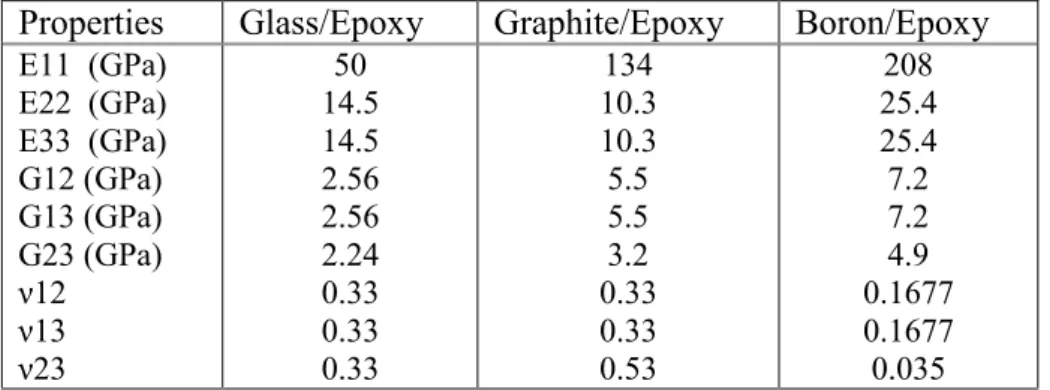
Table 1: Properties of the three composite laminates
Properties Glass/Epoxy Graphite/Epoxy Boron/Epoxy
E11 (GPa) E22 (GPa) E33 (GPa) G12 (GPa) G13 (GPa) G23 (GPa) ν12 ν13 ν23 50 14.5 14.5 2.56 2.56 2.24 0.33 0.33 0.33 134 10.3 10.3 5.5 5.5 3.2 0.33 0.33 0.53 208 25.4 25.4 7.2 7.2 4.9 0.1677 0.1677 0.035
Figure 1: Geometrical Model
To simulate the linear behavior in tension and the influence of fiber orientation and other parameters, we used the computer code Abaqus 6.7.1 [8] for the analysis of composite structures using the finite element method. This code provides a complete system, incorporating not only the actual calculation functions, also functions to build the model (preprocessor) and treatment of the outcomes (post-processor). To conduct this study, we have chosen a shell element whose elements are triangular of quadratic type.
Results and Discussion
Effect of the tilt inter-distance at 45° on the stress concentration factor
We have chosen the composite Boron / Epoxy to plot the contour of stresses with stratified layers with three orientations (0°, 45° and 90°). The composite material has two identical cavities of circular shape and is subject to tensile forces directed along the y-axis. The two notches are placed
next to each other relatively to the center of the structure and they occupy three different positions (horizontal, lateral and inclined at an angle of 45°). These are separated by a critical distance equal to 0.2 mm and their diameter equal to 6 mm.
Case of fiber orientation of 0°, 45° and 90°
Fig. 2a, 2b and 2c illustrate the amplitude and distribution of the equivalent stress on the contour of the cross-laminated composite which the stacks are oriented at 0°, 45° and 90°. Both holes are on the same line and are inclined with 45° with respect to the y-axis. It can be seen of figure 2a an increase of stresses the area that separates the two cavities, which is of the about three times greater than that of a single cavity taken separately in the cross-laminated composite. This increase in stress is probably due to the position occupied by two notches, the distance between them and the direction of reinforcement. The change in the geometrical shape of the cavity is due to a deformation of the composite material under the effect of high stresses. We notice for fig. 2b a slight deformation of the loaded area even with a stress level greater than that of stacks of 0°. This means that the laminate orientation in the same direction as the notches contribute to the structural strength of the composite.
For the case fig. 2c, there is a large deformation of the concave part of the two cavities and an important stress field on their convex portions whose intensity remains relatively less than that of the preceding stack. The reinforcements oriented at 90° have low mechanical strength, leading to very large deformations at the critical area subjected to high stress concentrations. The contours 2.4 and 6 correspond to composite boron / epoxy.
Figure 2: Contour of the equivalent stress for two circles placed on the same line, Inclined at 45° and at a critical distance of 0.2 mm (the fiber orientation: a: 0°, b: 45°
and c :90° )
We notice that the SCF reached maximum values when the distance between two holes is 0.2 mm as shown in Figure 3. Increasing the distance between two circular holes from the center of the structure leads to decrease the SCF to a constant value that is independent of the inter-circle-circle distance. This graph clearly shows that the composite glass/Epoxy with two cavities has a better resistance. For this numerical analysis, the fibers of the three composites laminated for the graphs 3, 5 and 7 are oriented at 45°
S, Mises Envelope (max abs) (Avg : 75%) +4.779e+02 +4.381e+02 +3.983e+02 +3.585e+02 +3.187e+02 +2.788e+02 +2.390e+02 +1.992e+02 +1.594e+02 +1.196e+02 +7.977e+01 +3.995e+01 +1.338e-01 S, Mises Envelope (max abs) (Avg : 75%) +9.775e+02 +8.961e+02 +8.147e+02 +7.334e+02 +6.520e+02 +5.707e+02 +4.893e+02 +4.079e+02 +3.266e+02 +2.452e+02 +1.638e+02 +8.248e+01 +1.121e+00 S, Mises Envelope (max abs) (Avg : 75%) +3.389e+02 +3.107e+02 +2.829e+02 +2.543e+02 +2.261e+02 +1.979e+02 +1.697e+02 +1.415e+02 +1.133e+02 +8.505e+01 +5.684e+01 +2.863e+01 +4.192e-01 a b c
Figure 3: Variation of the SCF versus tilt inter-distance at 45° for the three composites
Effect of the horizontal inter-distance on the SCF Case of fiber orientation of 0°, 45° and 90°
The contour of stresses in laminate stack at 0° and especially near the two holes placed horizontally and separated by an inter-distance of 0.2 mm, is shown in fig. 4a. We notice is a high stress concentration located in the critical region. As the two notches move away, the intensity of the equivalent stress decreases and the stress concentration is distributed on both sides of each notch. The fibers orientation of 0° affects slightly the variation of the geometrical shape of the two notches because in this direction the reinforcement increases the rigidity of the structure.
The fiber orientation at 45°, 4b, affects the circular shape of two cavities which changes into an ellipse, this is due to large deformations created at the critical area under the effect of a high stress field. For the case 4c we notice Von Mises stresses with intensive values at the critical zone. These stresses are superior to those with respective orientations of 0° and 45°.
Figure 4: Contour of the equivalent stress for two horizontal circles placed at a critical distance of 0.2 mm (fiber orientation: a: 0°, b: 45° and c: 90°)
0 10 20 30 40 50 60 70 80 90 100 2 4 6 8 10 12 14 16 18 20 S C F
Distance between the two holes [mm] Graphite/Epoxy Boron/Epoxy Glass/Epoxy
S, Mises Envelope (max abs) (Avg : 75%) +7.161e+02 +6.571e+02 +5.980e+02 +5.390e+02 +4.800e+02 +4.209e+02 +3.619e+02 +3.028e+02 +2.438e+02 +1.847e+02 +1.257e+02 +6.663e+01 +7.587e+00 S, Mises Envelope (max abs) (Avg : 75%) +7.353e+02 +6.742e+02 +6.130e+02 +5.518e+02 +4.906e+02 +4.294e+02 +3.683e+02 +3.071e+02 +2.459e+02 +1.847e+02 +1.236e+02 +6.239e+01 +1.217e+00 a S, Mises Envelope (max abs) (Avg : 75%) +1.163e+03 +1.066e+03 +9.697e+02 +8.732e+02 +7.766e+02 +6.800e+02 +5.835e+02 +4.869e+02 +3.904e+02 +2.938e+02 +1.972e+02 +1.007e+02 +4.116e+00 c b
Fig. 5 shows the variation of stress concentration factor based on the inter-circle-circle horizontal distance. We notice that the value of the SCF is amplified as the two notches get closer and reaches a maximum value which is about three times greater than that of a single hole placed in the structure. The increase of the distance between the two cavities decreases the level of the stress field. From the obtained results, it is necessary to separate the two cavities by a distance equal at least 16 mm in order to avoid high stress concentrations. In comparison with laminated composites Boron/Epoxy and Glass/Epoxy, the material Graphite/Epoxy has a low mechanical strength for a distance greater than 0.2 mm. We notice also that for small circle-circle distances the composite Graphite / Epoxy contributes more to the strengthening of cross-laminated structure.
Figure 5: Variation of the SCF versus the horizontal inter-distance for the three composites
Effect of lateral inter-distance on the SCF Case for fiber orientation of 0°, 45° and 90°
The contour of stresses in Figures 6a, 6b and 6c represent the intensity and equivalent stress distribution for respective fiber orientations 0°, 45° and 90°. We notice that the most significant stresses are equally distributed on both sides of both notches in the loading direction. Under the effect of high stress field, both notches deform into an oval shape, especially for 90° orientation. Unlike previous cases, a low stress field is observed in the separation zone of the two lateral cavities and especially for the 0° orientation.
Figure 6: Contour of the equivalent stress for two lateral circles placed side at a critical distance of 0.2 mm (fiber orientation: a: 0°, b: 45° and c 90°)
From fig. 7 we notice on one hand that the equivalent stress is distributed evenly between the two notches and on the other hand the lowest level of stress occurs for the composite material Glass/Epoxy because it has good mechanical strength with respect to the other two cross Composite
S, Mises Envelope (max abs) (Avg : 75%) +3.020e+02 +2.769e+02 +2.518e+02 +2.266e+02 +2.015e+02 +1.764e+02 +1.512e+02 +1.261e+02 +1.009e+02 +7.581e+01 +5.067e+01 +2.554e+01 +4.020e-01 0 10 20 30 40 50 3,0 3,5 4,0 4,5 5,0 5,5 6,0 6,5 7,0 7,5 8,0 8,5 9,0 9,5 10,0 10,5 11,0 Graphite/Epoxy Boron/Epoxy Glass/Epoxy
Distance between the two holes [mm]
S
C
F
S, Mises Envelope (max abs) (Avg : 75%) +2.768e+02 +2.539e+02 +2.311e+02 +2.032e+02 +1.854e+02 +1.625e+02 +1.397e+02 +1.168e+02 +9.394e+01 +7.108e+01 +4.822e+01 +2.537e+01 +2.512e+00 S, Mises Envelope (max abs) (Avg : 75%) +1.578e+02 +1.447e+02 +1.316e+02 +1.185e+02 +1.054e+02 +9.232e+01 +7.922e+01 +6.613e+01 +5.303e+01 +3.993e+01 +2.683e+01 +1.874e+01 +6.397e-01 a b c
We notice also an opposite behavior to that of horizontal and inclined positions of the two cavities. Indeed, when the two side notches get closer to each other, the concentration factor is reduced by 6%, 4% and 3% respectively for the composites Glass/Epoxy, Boron/Epoxy and Graphite/Epoxy. Therefore, the influence of the inter-distance notch to notch on the SCF is negligible. Increasing the distance between the two notches led to Von Mises stresses almost constant.
Figure 7: Variation of SCF versus to the inter-lateral distance for the three composites.
Effect of fiber orientation on the SCF for a critical inter distance
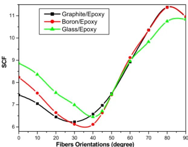
Fig. 8 represents the variation of SCF versus the fibers orientation for a critical inter-distance of 0.2 mm between the two notches. These last two are placed on a line inclined at an angle of 45° with respect to the y-axis. We notice that the shape of the curve of the SCF is the same for the three cross-laminated composites. The cross-laminated composite Graphite/Epoxy has a high level of SCF compared to the composite Glass/Epoxy and Boron/Epoxy.
Figure 8: Variation of the SCF versus the fibers orientations for critical tilt inter-distance at 45°.
The change of the SCF with the orientations of the fibers with horizontal cavities located on each side of the origin at a distance of 0.2 mm for the three composite, is represented on fig. 9. Compared with the results found previously, this curve is the inverse of that of fig. 8 and it presents a danger to the structure with fiber orientation at 90°.
0 10 20 30 40 50 60 70 80 90 6 8 10 12 14 16 18 Graphite/Epoxy Boron/Epoxy Glass/Epoxy
Fibers Orientations (degree)
S C F 0 20 40 60 80 100 3,2 3,3 3,4 3,5 3,6 3,7 3,8 3,9 4,0 4,1 4,2 4,3 4,4 4,5 4,6 4,7 4,8 4,9 5,0 5,1 S C F
Distance between the two holes [mm]
Graphite/Epoxy Boron/Epoxy Glass/Epoxy
Figure 9: Variation of the SCF versus the fibers orientations for the critical horizontal distance.
Fig. 10 shows the variation of the SCF with respect to the orientation of the laminated layers with lateral notches of circular shape. The latter are positioned parallel to the loading, each of them is at a distance of 0.2 mm from the origin of the structure. We notice that the three curves of the three SCF materials have a similar appearance. The arrangement of the notches in the direction of the y-axis results in low SCF values compared to horizontal and inclined notches at an angle of 45°, especially for glass/epoxy for 30° fiber orientation. The fiber orientation at 90° presents a risk of initiation and propagation of delaminating in cavities.
Figure 10: Variation of the SCF versus the fibers orientations for the critical vertical distance.
Conclusions
In this work, we studied the mechanical behavior of three composite cross laminates under monotonic loading: Graphite/Epoxy, Boron/Epoxy and Glass/Epoxy. Our numerical study aim is to analyze the stress concentration factor under the influence of parameters such as geometry, mechanical properties and hole to hole interaction. The two cavities are placed near the center of cross-laminated and occupy three positions (horizontal, lateral and inclined at an angle of 45°). This study allowed us to draw the following conclusions:
0 10 20 30 40 50 60 70 80 90 2,5 3,0 3,5 4,0 4,5 5,0 S C F
Fibers Orientations (degree)
Graphite/Epoxy Boron/Epoxy Glass/Epoxy 0 10 20 30 40 50 60 70 80 90 6 7 8 9 10 11 S C F
Fibers Orientations (degree)
Graphite/Epoxy Boron/Epoxy Glass/Epoxy
The interaction hole/hole has a great influence on the variation of the stress concentration factor on one hand at the area of separation of the two circular notches in positions that are horizontal and inclined at an angle of 45° and on the other hand at the convex portions of the two lateral cavities. The increasing distance between the two notches leads to Von Mises stresses which are almost constant and distributed on both sides of the circular notches. In the case where the two circular notches are placed laterally, the cross-laminated composite (Glass/Epoxy) has the lowest stress concentration factor in comparison with those of Graphite/Epoxy and Bore/Epoxy.
References
[1] T. K. Paul and K. M. Rao, Flexural Analysis of Laminated Composite Plates Containing two Elliptical Holes Using Higher-Order Shear Deformation Theory. Computers & Structures Vol. 55. No. 2. pp. 279-285. 1995
[2] N.T. Younis, Assembly stress for the reduction of stress concentration, Mechanics Research Communications 33 (2006) 837–845
[3] Xu Xiwu, Sun Liangxin and Fan N Xuqi, Stress Concentration of Finite Composite Laminates Weakened by Multiple Elliptical Holes. Inr. J. Solids Structures Vol. 32, No. 20, pp. 3001-3014, 1995
[4] Paul TK, Rao KM. Finite element evaluation of stress concentration factor of thick laminated plates under transverse loading. Computers and Structures 1993;
[5] K. Ting, K.T. Chen, W.S. Yang, Stress analysis of the multiple circular holes with the rhombic array using alternating method, International Journal of Pressure Vessels and Piping 76 (1999) 503– 514
[6] L. Toubal, M. Karama, B. Lorrain, Composite Structures 68 (2005) 31–36
[7] H. Mahiou, A. Bekaou, Composites Science and Technology 57 (1997) 1661–1672.
[8] ABAQUS Finite Element Program, ABAQUS/Standard 6.7.1. Hibbit, Karlsson and Sorensen, Inc. Pawtuket, USA, 2006.
Mechanical Behavior of Laminated Composites with Circular Holes 10.4028/www.scientific.net/KEM.550.1