FP
14 1967
1 /8RA RIE COMPUTER SIMULATION OF NEUTRONCAPTURE THERAPY
by
Arne Peter Olson
B.A.Sc., University of British Columbia (1964)
SUBMITTED IN PARTIAL FULFILLMENT OF THE REQUIREMENTS FOR THE DEGREE OF
DOCTOR OF SCIENCE
at the
MASSACHUSETTS INSTITUTE OF TECHNOLOGY
August, 1967
Signatnre of Author
Department of Nuclear Engineering, August 1967
Certified by_
COIPUTER SDAULATION OF NEUTRON CAPTURE THERAPY
by
Arne Peter Olson
Submitted to the Department of Nuclear Engineering on August 21, 1967 in partial fulfillment of the requirement for the degree of
Doctor of Science.
ABSTRACT
Analytical methods are developed to simulate on a large digital computer the production and use of reactor neutron beams f or boron capture therapy of brain tumors. The simulation accounts for radiaticn dose distributions in tissue produced by fast neutrons and by neutron capture reaction products such as gamma rays, C -particles, protons, and heavy particles. These techniques are applied to optimize the effectiveness of the M.I.T. Reactor Medical Therapy Facility through
a survey of the effects of neutron filters and of modifications to the
beam collimation system. Neutron beams reflected from thin slabs of
hydrogenous materials are shown to have an improved ability to
effec-tively irradiate a deep tumor without destroying normal tissue above it because relatively few fast neutrons are reflected. Considerable improvements in thermal neutron distribution in tissue are shown to result from surrounding the head with a neutron-reflecting annulus to reduce lateral neutron leakage.
A new numerical solution is obtained for the problem of neutron transport in finite thickness slabs with isotropic scattering. Gaus-sian quadratures are used to evaluate the neutron transport integral
equations, yielding transmission, absorption, and reflection probab-ilities, and fluxes, as a function of collision number. Collision history correlations are devised which use only five parameters to predict the fate of neutrons incident on an infinite slab having arbitrary thickness and neutron cross sections. A very fast
multi-group neutron spectrum calculation is developed by combining collision
history correlations with single-collision group transfer probabilities to directly obtain transmission and mflection matrices for multi-slab
shielding problems.
Thesis Supervisor: Gordon L. Brownell
ACKNOWLEDGEMENTS
The author is deeply indebted to Professor Gordon L. Brownell for his constant enthusiasm and advice during the conduct of this work. Helpful discussions with Professors K. F. Hansen and N. C. Rasmussen are gratefully acknowledged. Dr. Reddy and Dr. Ayyangar of the Massachusetts General
Hospi-tal Physics Research Laboratory have worked in close association with the author to the benefit of all concerned, in order to relate their experimental program to the theoretical studies in this thesis. R. G. Fairchild, of the Medical Physics Division, Brookhaven National Laboratory, has been most help-ful in comparing his experimental studies of epi-thermal neutron beams with a computer simulation by
the author. This work would not have been
possible without the Gerard Swope Fellowship awarded
by M.I.T. for academic year 1964-65. Financial
support from June 1965 to September 1967 in the form
of a full-time Research Assistantship was provided by the Physics Research Laboratory (M.G.H.). The
Physics Research Laboratory also provided computer time at the Harvard Computation Center from June 1965 to September 1966. Computing time since September
1966 has been provided by the Nuclear Engineering
BIOGRAPHICAL NOTE
The author was born in Kimberley, British Columbia, on August 9, 1939. He attended the
University of British Columbia at Vancouver, Brit-ish Columbia, Canada, from September 1958 to May
1962, and from September 1963 to May 1964. He
was graduated in May 1964, with the degree of
Bachelor of Applied Science in Engineering Physics. Aerodynamics was the minor program. The author was
employed as a Research Technician by the Reactor Physics Division of Atomic Energy of Canada, Ltd., Chalk River, Ontario, from May 1962 to September
1963 and from May 1964 to September 1964. While
at Chalk River he wrote two computer codes which have been extensively used for three-dimensional fuel management and lifetime studies of the NPD and CANDU heavy water power reactors. He is the author of three Chalk River Reports on this work:
"APOGEE - A Computer Program to Solve the
One-Group Neutron Diffusion Equation in Three Dimensions". A.E.C.L.-1799 (CRRP-1159),
July, 1963;
"PERIGEE - Computer Codes for Reactor Simu-lation in 3 Dimensions, Using 1 or 2 Neutron Velocity Groups". A.E.C.L.-1901 (CRRP-1184), Feb., 1964;
"Appendix I to A.E.C.L.-1901". A.E.C.L.-2095 (CRRP-1184), Sept., 1964.
While at Chalk River he met and married the former Carol Slater, a Second Grade teacher from Toronto.
A daughter, Jennifer, is now one year old.
The author was awarded a Gerard Swope Fellow-ship by the Massachusetts Institute of Technology for academic year 1964-65. Concurrently awarded, but declined, was a National Research Council of Canada Fellowship and a University of Toronto
Institute of Aerophysics Fellowship. He was a full-time Research Assistant in the Nuclear Engineering Department under Professor G. L. Brownell at the Massachusetts General Hospital from June 1965 to
September 1967. Some of the work performed as a Research Assistant has been reported as follotis:
"Computer Prediction of Neutron-Capture Therapy Radiation Dose for the M.I.T.R. Medical
Ther-apy Facility Beam", Trans. Am. Nuc. Soc. 9, 74 (1966).
"Selection of Neutron Beam Characteristics for Neutron Capture Therapy", A. P. Olson and
G. L. Brownell, TID-23054. Int. Conf. on the Use of Computers in Therapeutic Radiology,
14-17 June, 1966, Cambridge, England.
The author is a student member of the American Nuclear Society and the Engineering Institute of Canada.
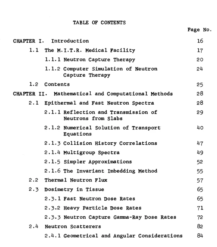
TABLE OF CONTENTS
Page No.
CHAPTER I. Introduction 16
1.1 The M.I.T.R. Medical Facility 17
1.1.1 Neutron Capture Therapy 20
1.1.2 Computer Simulation of Neutron 24
Capture Therapy
1.2 Contents 25
CHAPTER II. Mathematical and Computational Methods 28
2.1 Epithermal and Fast Neutron Spectra 28
2.1.1 Reflection and Transmission of 29
Neutrons from Slabs
2.1.2 Numerical Solution of Transport 40 Equations
2.1.3 Collision History Correlations 47
2.1.4 Multigroup Spectra 49
2.1.5 Simpler Approximations 52
2.1.6 The Invariant Imbedding Method 55
2.2 Thermal Neutron Flux 57
2.3 Dosimetry in Tissue 65
2.3.1 Fast Neutron Dose Rates 65
2.3.2 Heavy Particle Dose Rates 71
2.3.3 Neutron Capture Gamma-Ray Dose Rates 72
2.4 Neutron Scatterers 82
CHAPTER III. Test Problem Results 88 3.1 Monoenergetic Neutrons in a Thin Slab 88
(Isotropic Scattering in Lab.)
3.1.1 Collision History Correlations 90
3.1.2 Comparison with Markov Matrix 111
Method
3.1.3 Comparison with Invariant 114
Imbedding Method
3.1.4 Accuracy of the Calculations 116
3.2 Transmission of Fission Neutrons by 118
Polyethylene
3.3 Transmission of Fission Neutrons by D20 124 CHAPTER IV. Comparison with Experiment at the 130
Brookhaven Medical Research Reactor
4.1 The M.R.R. Medical Facility 130
4.2 Experimental Measurements 132
4.3 Computer Simulation 134
CHAPTER V. Results for the M. IT.R. Medical Facility 144
5.1 Introduction 144
5.2 Computer Simulation 145
5.3 Epithermal Neutron Beams 154
5.4 The Use of Neutron Filters 161
5.5 The Use of Scattered Neutrons 177
5.6 The Use of a Reflecting Annulus 208
CHAPTER VI. Conclusions 212
6.1 Computational Methods 212
A.1 MEDIPORT
A.l.1 Input Data
A.l.2 Listing of MEDIPORT
A.1.3 Sample Problems for MEDIPORT A.1.4 Gaussian Integration
A.1.5 Numerical Interpolation
A.2 TAR(N)
A.2.1 Input Data for TAR(N) A.2.2 Listing of TAR(N)
A.2.3 Sample Problem for TAR(N) A.3 LPF
A.3.1 Input Data for LPF
A.3.2 Listing of LPF
A.3.3 Sample Problem for LPF
A.4 STAR DATA REDUCTION
A.4.1 Input for SDR
A.4.2 Listing of SDR
A.4.3 Sample Problem for SDR
A.5 Modifications to CSDP
A-5.1 Listing of SEC5 for CSDP
A.6 Modifications to STAR
A.6.1 Listing of STAR Modifications
APPENDIX B. Bibliography 223 226 237 259 270 272 274 276 279 288 296 298 299 303 310 313 315 319 324 326 330 332 340
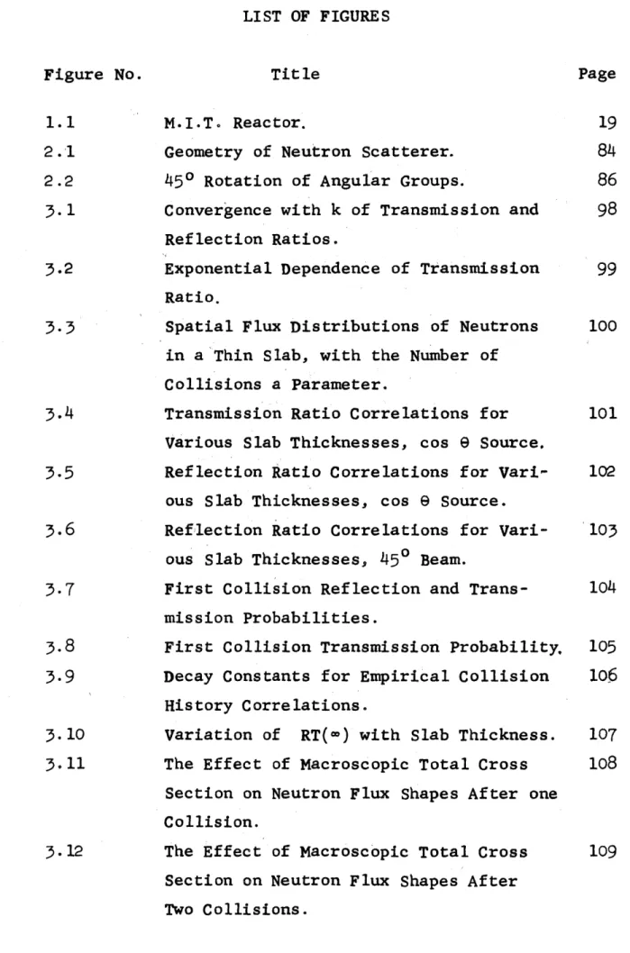
Figure No. Title Page
1.1 M.I.T. Reactor. 19
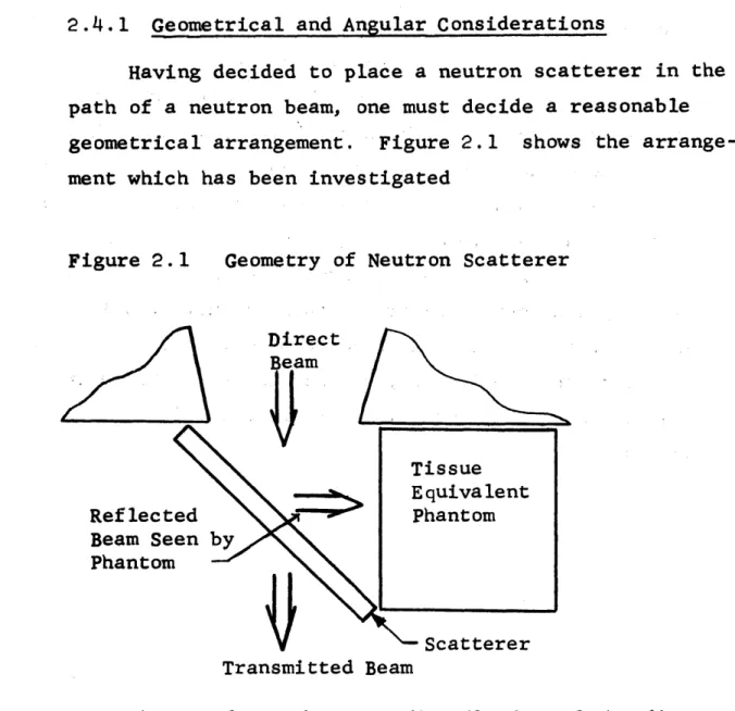
2.1 Geometry of Neutron Scatterer. 84
2.2 450 Rotation of Angular Groups. 86
3.1 Convergence with k of Transmission and 98 Reflection Ratios.
3.2 Exponential Dependence of Transmission 99
Ratio.
3.3 Spatial Flux Distributions of Neutrons 100
in a Thin Slab, with the Number of Collisions a Parameter.
3.4 Transmission Ratio Correlations for 101
Various Slab Thicknesses, cos
e
Source,3.5 Reflection Ratio Correlations for Vari- 102 ous Slab Thicknesses, cos 9 Source.
3.6 Reflection Ratio Correlations for Vari- 103
ous Slab Thicknesses, 450 Beam.
3.7 First Collision Reflection and Trans- 104 mission Probabilities.
3.8 First Collision Transmission Probability, 105
3.9 Decay Constants for Empirical Collision 106 History Correlations.
3.10 Variation of RT(w) with Slab Thickness. 107
3.11 The Effect of Macroscopic Total Cross 108
Section on Neutron Flux Shapes After one Collision.
3.12 The Effect of Macroscopic Total Cross 109
Section on Neutron Flux Shapes After Two Collisions.
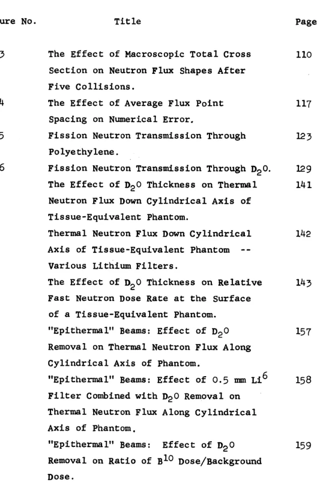
Figure No. Title Page 3.13 The Effect of Macroscopic Total Cross 110
Section on Neutron Flux Shapes After Five Collisions.
3.14 The Effect of Average Flux Point 117
Spacing on Numerical Error.
3.15 Fission Neutron Transmission Through 123
Polyethylene.
3.16 Fission Neutron Transmission Through D20. 129
4.1 The Effect of D20 Thickness on Thermal 141 Neutron Flux Down Cylindrical Axis of
Tissue-Equivalent Phantom.
4.2 Thermal Neutron Flux Down Cylindrical 142 Axis of Tissue-Equivalent Phantom
--Various Lithium Filters.
4.3 The Effect of D20 Thickness on Relative 143 Fast Neutron Dose Rate at the Surface
of a Tissue-Equivalent Phantom.
5.1 "Epithermal" Beams: Effect of D20 157
Removal on Thermal Neutron Flux Along Cylindrical Axis of Phantom.
5.2 "Epithermal" Beams: Effect of 0.5 mm Li6 158
Filter Combined with D20 Removal on
Thermal Neutron Flux Along Cylindrical Axis of Phantom.
5.3 "Epithermal" Beams: Effect of D20 159 Removal on Ratio of B10 Dose/Background
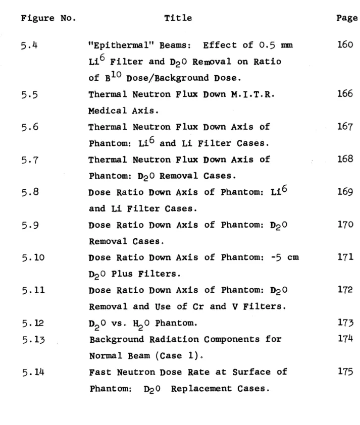
Figure No. Title Page 5.4 "Epithermal" Beams: Effect of 0.5 mm 160
Li6 Filter and D20 Removal on Ratio of B1 0 Dose/Background Dose.
5.5 Thermal Neutron Flux Down M.I.T.R. 166
Medical Axis.
5.6 Thermal Neutron Flux Down Axis of 167
Phantom: Li6 and Li Filter Cases.
5.7 Thermal Neutron Flux Down Axis of 168
Phantom: D20 Removal Cases.
5.8 Dose Ratio Down Axis of Phantom: Li6 169
and Li Filter Cases.
5.9 Dose Ratio Down Axis of Phantom: D2 0 170
Removal Cases.
5.10 Dose Ratio Down Axis of Phantom: -5 cm 171 D20 Plus Filters.
5.11 Dose Ratio Down Axis of Phantom: D2 0 172
Removal and Use of Cr and V Filters.
5.12 D20 vs. 1120 Phantom. 173
5.13 Background Radiation Components for 174
Normal Beam (Case 1).
5.14 Fast Neutron Dose Rate at Surface of 175
Figure No. Title Page 5.15 Fast Neutron Dose Rate at Portal: Effect 176
of Removal of D20 and Bi.
5.16 Integral Spectrum at Portal of M.I.T.R. 182
Medical Beam.
5.17 Epithermal and Fast Neutron Spectrum at 183
Portal of M.I.T.R. Medical Beam.
5.18 Fast Neutron Dose Transmitted by Infinite 184
Slabs of Lucite, Tissue, H20, and Polyethylene.
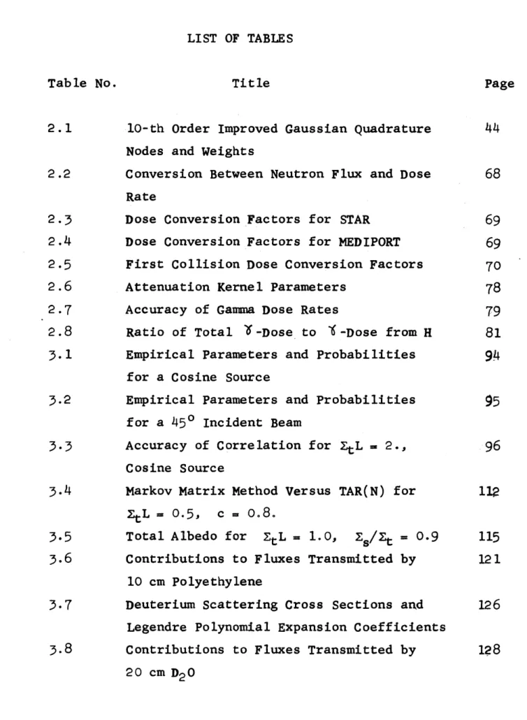
LIST OF TABLES
Table No. Title Page
2.1 10-th Order Improved Gaussian Quadrature 44 Nodes and Weights
2.2 Conversion Between Neutron Flux and Dose 68
Rate
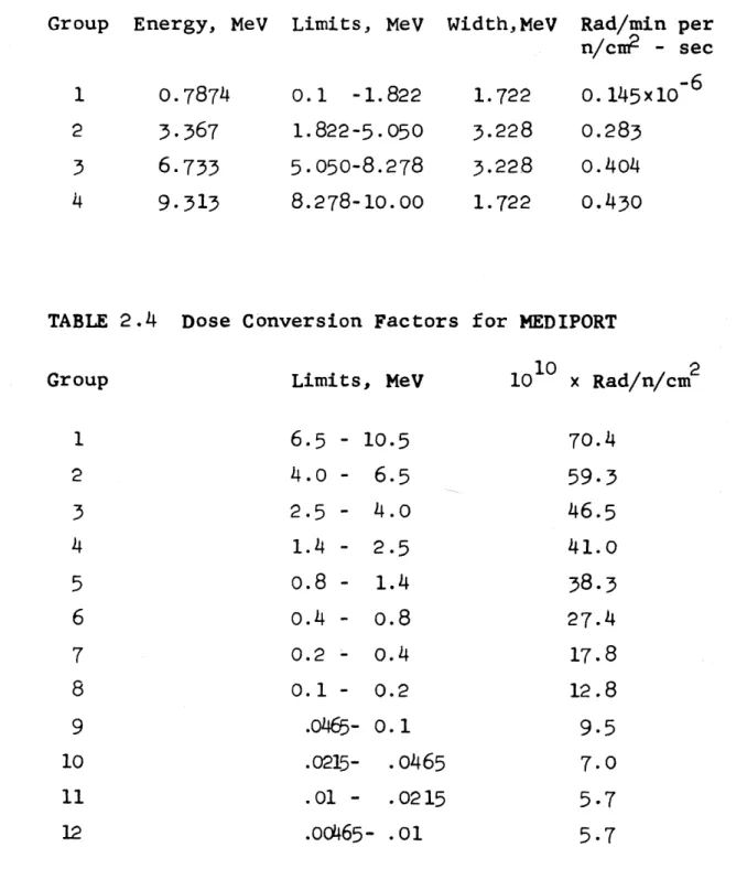
2.3 Dose Conversion Factors for STAR 69
2.4 Dose Conversion Factors for MEDIPORT 69
2.5 First Collision Dose Conversion Factors 70
2.6 Attenuation Kernel Parameters 78
2.7 Accuracy of Gamma Dose Rates 79
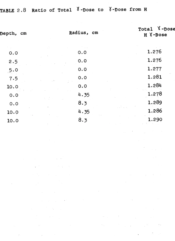
2.8 Ratio of Total 7-Dose to I-Dose from H 81 3.1 Empirical Parameters and Probabilities 94
for a Cosine Source
3.2 Empirical Parameters and Probabilities
95
for a 450 Incident Beam
3.3 Accuracy of Correlation for ZtL = 2., 96
Cosine Source
3.4 Markov Matrix Method Versus TAR(N) for 112
=tL
0
0.5,c
=o.8.
3.5 Total Albedo for ZtL = 1.0, Zs/t = 0.9 115 3.6 Contributions to Fluxes Transmitted by 121
10 cm Polyethylene
3.7 Deuterium Scattering Cross Sections and 126
Legendre Polynomial Expansion Coefficients
3.8 Contributions to Fluxes Transmitted by 128
4.1 MRR Geometry, All 18.0 cm D20 in Place 135
5.1 Medical Beam Port Geometry for Shutters 149
5.2 M.I.T.R. Cases Studied 163
5.3 Neutron Spectra Through Exact and 178
Simplified Geometries
5.4 Neutron Spectrum at Portal 179
5.5 Scalar Flux and Dose at Portal 179
5.6 Fast Neutron Spectra in Various Phantoms 185 5.7 First Collision Dose at Depth in Tissue 186
5.8 Neutron Energy Dependence of Fast 187
Neutron Dose Rate Transmitted by
Infinite Slabs of Tissue, Lucite, H20 and Polyethylene
5.9 Flux and Dose in Tissue: 450 Lucite 188
Scatterers
5.10 Flux in Tissue: 450 H20 Scatterers 192
5.11 Flux in Tissue: 450 Polyethylene Scat- 196
terers.
5.12 Perfectly Reflecting Slab: 450 Incident 202 Beam
5.13 Lucite Scatterer: Reflection Probabil- 203
ities
5.14 Flux and Dose Rates in Phantom: Direct 206
Beam, M.I.T.R.
5.15 Flux and Dose Ratesin Phantom: 0.5 cm 207
Lucite Scatterer, M.I.T.R.
5.16 Relative Thermal Neutron Flux in Phantom 210
with Reflecting Annulus (Phantom Radius 8.3 cm).
Table No. Title Page
5.17 Thermal Neutron Flux Enhancement in 211
Phantom with Reflecting Annulus (Phantom Radius 8.3 cm).
CHAPTER I
INTRODUCTION
The purpose of this thesis is twofold: to develop analytical methods for simulating, via computer, the production and use of reactor neutron beams for boron
capture therapy of brain tumors, and to apply these techniques to survey and optimize the effectiveness of the M.I.T. Reactor Medical Therapy Facility.
1.1 The M.I.T.R. MEDICAL FACILITY
The M.I.T.R. is an enriched uranium, heavy water moderated research reactor which normally operates at a power level of 5MW (thermal). The Medical Therapy Facility is a fully equipped surgical operating room
located directly beneath the reactor core, as is shown in Figure 1.1. The room has thick concrete walls, a motor-driven sliding shielded door, and an oil-filled viewing window to allow operating personnel to control, observe, and monitor the irradiation from outside the room with negligible radiation hazard.
The operating table can be elevated hydraulically to position, the patient under the neutron beam port in the ceiling. Sheets of lithium fluoride-loaded
plastic serve as a collimator to channel neutrons directly to the tissue to be irradiated, and lead sheets serve as a gamma-ray shield to protect the rest of the body.
The neutron beam passes through a collimator con-taining three shutters which are opened during irradi-ations. Radiation levels, with shutters closed, are low enough to permit working inside the room for limited
periods of time during full power operation of the reactor. The primary shield, nearest the reactor core, is a drainable tapered aluminum tank containing a thickness of about three feet of light water. Lead and boral plates located in the ceiling of the medical room comprise the
other two shutters. They shield gamma rays and thermal neutrons, respectively.
With all shutters open, neutrons leaving the core travel through 21.0 inches of heavy water, 9.81 inches of bismuth, 0.625 inches of aluminum, and 56.75 inches of air. Bismuth is used because it combines low neutron absorption with strong gamma ray attenuation. The heavy water, forming the lower
reflector for the core, is a strong moderator of fast neutrons. Hence the emergent beam is well thermalized.
DENSE
CONCRETE
GRAPHITE
-FUEL
PORT-OBSERVATION
WINDOW
MEDICALTHERAPY ROOM
CONTROL RODS NPE
1.1.1 NEUTRON CAPTURE THERAPY
The medical use of thermal neutron beams for capture therapy to destroy tumor tissue was first proposed in 1936 by Locher.1 If a suitable neutron capturing isotope could be preferentially concentrated in tumor tissue, neutron irradiation will produce a
large local radiation dose to the tumor with minimal damage to normal cells. This technique is known as neutron capture therapy. In common with all forms of radiation therapy, it uses the fact that the survival probability of irradiated cells has a marked dose threshold. In order to minimize the damage to normal cells, one must first select an isotope whose neutron absorption reaction products have a short range in tissue. Then a non-toxic compound must be synthesized which strongly concentrates in tumor tissue. Finally, a neutron beam is required which is able to deliver a
large thermal neutron flux to the tumor.
Sweet and Javid 2 demonstrated that boron could be preferentially concentrated in human brain tumor tissue to a sufficient degree to warrant attempts at
therapy. Clinical trials were carried out at Brookhaven 3 and at the M.I.T.R. and the Massachusetts General
Hospital. The disappointing results led to termin-ation of patient irraditermin-ations in 1961 although basic
chemical, biological, and physical studies have continued to the present time. The clinical trials demonstrated
10
the need for reduced B concentration in blood and blood vessels, improved dosimetry to monitor the irradiations, and improved neutron beam characteristics to maximize its effectiveness for neutron capture therapy.
The present status of boron capture therapy has recently been reviewed with particular attention to the properties of boron compoundsA 5 Many
com-pounds have recently been made and tested for toxicity and pharmacology. Both concentration and localization in tumor have been of particular interest. Three main classes of compounds have been considered:
I Boron-containing Antimetabolites A. Amino Acids B. Pyrimidines C. Purines II Borono Proteins A. Tumor Antibodies
III Alkylating Agents Containing Boron
Group I compounds may interfere with tumor meta-bolism and replication, thereby inhibiting growth. They may also be capable of mimicking normal biologi-cal constituents and become readily incorporated into the tumor cell. Boron-labeled proteins of Group II have been synthesized with 1-3% boron by weight. It has been found that I131-labeledantifibrin antibodies
localize in tissues such as brain tumors. Attempts have been made to incorporate boron in such compounds. Group III compounds are known tumor growth inhibitors which have been altered by introducing a boron atom
within the molecule. Alkylating agents interact with tumor nucleic acids. The strategic location of a
boron atom at the interaction site followed by neutron irradiation would have a profound effect on tumor
growth by destroying its ability to replicate.
Two compounds have recently been synthesized 6 which look very promising.
Compound Boron Concentration Ratio
Tumor/Blood Tumor/Brain
CS2B12HjjSH 6:1 16:1
Na2 B12HllSH 8:1 25:1
They will be tested in humans within six months for toxicity and pharmacology. Irradiations will probably take place within a year at the M.I.T. reactor.
1.1.2 COMPUTER SIMULATION OF NEUTRON CAPTURE THERAPY
The need for improvements in neutron beam character-istics for neutron capture therapy has been clearly shown by the results of the clinical trials of several years ago. The enormity and cost of modifying the existing reactor collimator structure and experimentally analyzing the beam characteristics obviously precludes this approach. If, on the other hand, a reasonable physical model of this system could be coded for a large digital computer, the effects of hypothetical modi-fications to materials and geometrical arrangements could rapidly be surveyed. In addition, the computer studies would be of value both to analyze practical experiments and
to suggest new experiments. These ideas form the rationale for this thesis.
1.2 CONTENTS
The physical model for neutron capture therapy involves describing the passage of polyenergetic neutrons from the reactor core through numerous and varied layers until finally
the neutrons penetrate tissue - or a tissue-equivalent phan-tom head. Chapter II begins with a consideration of neutron transmission through infinite slabs in Section 2.1.1.
Section 2.1.2 examines a new numerical integration solution to the transport equations based on solving for spatial distributions of neutrons suffering the same number of
collisions. Collision history correlations are discussed in Section 2.1.3 to show how the solution for monoenergetic neutrons in a non-absorbing, non-multiplying slab yields
solutions for all slabs of the same thickness but different absorption or multiplication. An approach to the problem
of polyenergetic neutron transmission through slabs is pre-sented in Section 2.1.4. Simpler approximations which have been used to obtain spectral shapes are discussed in
Section 2.1.5.
One-dimensional spatial distributions of thermal neutron flux are obtained by replacing the second-order diffusion equation by a system of three coupled, linear, first-order differential equations, which can be numerically integrated. The derivation of this equation is presented in Section 2.2, along with a discussion of boundary conditions and the
Section 2.3 is concerned with the calculation of radi-ation dose rates from all sources in a tissue-equivalent phantom head of cylindrical shape, when bombarded by a beam of neutrons.
The use of scattered neutrons, rather than a direct beam, for neutron capture therapy, has many promising
aspects. Methods used to attack this problem are discussed in Section 2.4.
Test Problem results are given in Chapter 3, Section 3.1, dealing with monoenergetic neutrons incident on thin infinite slabs which scatter neutrons isotropically in the lab. system. Comparisons are made with two other solutions to this problem which are referred to as the Markov Matrix Method and the
Invariant Imbedding Method.
Fast Neutron transmission through 30 cm of polyethylene is a more practical, and difficult, test of the methods used to calculate neutron transmission. Section 3.2 deals with this problem, and draws comparisons with Invariant Imbedding
results. Section 3.3 gives results for neutron transmission through a 40 cm thick slab of D20.
A rather extensive set of experiments was performed by R. G. Fairchild, using the Brookhaven Medical Research
Reactor to evaluate the production and use of "epithermal" neutron beams for neutron capture therapy. Chapter IV is devoted to comparisons of this work and results obtained
Chapter V gives results for the M.I.T.R. Medical Facility, and deals successively with heavy water removal effects, thermal neutron filter effects, fast neutron filter effects, and the use of scattered neutrons.
Conclusions are given in Chapter VI, while Appendix
A describes all computer codes used. Appendix B contains
CHAPTER II
MATHEMATICAL AND COMPUTATIONAL METHODS
2.1 EPITHERMAL AND FAST NEUTRON SPECTRA
Many shielding codes and methods have been developed for routine problems in reactor design. Highly accurate results are obtainable if the need justifies the cost in computer time and man-hours. However, for calculations involving numerous variations from a reference condition, such as a parametric survey, it is often easier to perform a few "bench-mark" calculations using the best possible methods, and to explore around the "bench-marks" by less accurate methods. For example, prediction of absolute neutron fluxes transmitted through a complicated shield is extremely difficult, whereas small departures from a given geometry can be predicted, relatively, with much less effort.
It is the purpose of this chapter to present a very fast method for performing polyenergetic neutron trans-mission and reflection problems, suitable for survey
calcu-lations, which has been used in conjunction with a few
bench-mark calculations obtained by the method of Invariant Imbedding.
2.1.1 REFLECTION AND TRANSMISSION OF NEUTRONS FROM SLABS
The general problem to be considered is that of neutron reflection, absorption and transmission through a homogeneous plane infinite slab or series of slabs of arbitrary neutron cross sections. For simplicity, the single slab will be considered first.
The Transmission Matrix Method described by Aronson and Yarmush7 offers a unified approach to the solution of a
large variety of neutron transport problems in plane geometry. The formulation in terms of transfer matrices can be thought
of as an alternative to the formulation in terms of the differ-ential or integral linearized Boltzmann equations. A brief
summary of the mathematical formulation of the Transmission Matrix Method is presented below, because its concepts
carry over directly to the simplified treatment developed and used in this thesis.
Let Xi and X2' be neutron fluxes incident from the left and right, respectively. They are functions of incident angle and neutron energy for a source-free slab. X1' is the emergent flux on the right and X2 on the left. Assuming
the problem is linear
x1 =TX + R*X2 1
(2.1) X2 = RX1 + T*X
2
where T and R are transmission and reflection operators for neutrons incident from the left, and T* and R* for neu-trons incident from the right. If the slab is symmetric, T = T*, and R = R*. Equations (2.1) may be solved for Xil' and X2' to give in matrix form
- 1 -
-- H X(2.2)
-X 2 - _X2
-where H is a 2 x 2 matrix of operators:
T *U*R R*U
H (2.3)
with
Equation (2.2) yields a composition law for H matrices:
H = Hn ''' E2!!1 (2.5)
for n layers, with Hi associated with the i-th layer. For a two-layer problem one obtains total transmission T and total reflection R as follows:
-l T T2 1 R2) 1 2 (T+ R 2 1 + (E* R 2 -T + (2.6) 2 (* 2 n 1 n_- o R -l T2 ( - 2 1 1 -21 -1 R1+ T 1 E .* R 2)1-T (2.7) -l -1-2 \IR7 -1+ - -2 1, -l n o
The series expansions (2.6) and (2-7) have a simple physical interpretation. For instance, T,* R2 (Rl )n T represents transmission through slabs 1, n pairs of reflec-tions back and forth at the interface, a final reflection from slab 2, and transmission back through slab 1.
The problem is to obtain the H-matrix in terms of
physical properties of the slab. A new matrix W depending only on the neutron cross sections can be formulated. For a slab of thickness t:
H = exp (-Wt)
is the formal relationship required. Up to this point, everything is exact. But to deal with a real problem, a discrete representation of neutron energy and angle must be chosen. This converts integral operators to matrices, and one obtains a mathematical system which can be solved
on a large digital computer.
The particular concepts taken from the Transmission Matrix Method and used in this thesis are expressed by
Equations (2.6) and (2.7). A method has been developed which directly yields the transmission and reflection matrices
T1' 12' Tl' R2, from which T and R are obtained by use of
(2.6) and (2.7).
The original concept for the calculation of the reflec-tion and transmission operators R , Ti (for slab i) stemmed largely from the work of Eaton and Huddleston8 on a Markov Matrix Method for slab problems. They consider a
homogen-eous, infinite slab of thickness L with macroscopic absorption, scattering, and total cross sections of Za' zs, and
t = zAa + s The probabilities for scatter and absorption at a collision are c = Zs t, and 1 - c = Za / t
respectively. Scattering is assumed to be isotropic in the laboratory system.
In order to apply the Markov chain concept, the slab must be conceptually divided into n discrete layers each of
thickness s = L/n, where s(( 1/t Upon including the semi-infinite voids on either side of the slab, one obtains n + 2 Markov states. The probability that a neutron
incident at polar angle 9 has its first collision in the i-th state (layer) is
P(i) = sec 9
Z
exp(-Zt
sec 90 t ) dt (i-l)s= exp [-t sec 9 (i-1)s - exp (-zt sec 90 is),
i=1, 2, -e-n (2.8)
and
P(O) = 0 (no impacts in a void)
P(n+l) = L t
sec 90 exp(-Zt sec 9 t) dt (2.9
= exp (-Zt sec 99 L)
= uncollided transmission probability.
These probabilities are the ordered elements of the Markov initial state vector V .
V1 =
LP(O),
P(l), .- P(n), P(n+l) (2.10)Now a transition matrix M is required such that
V J = V M,0 j 1,2,.. (2.11)
where the 1-th element in any V approximates the probability that the neutron will experience a J-th impact in the i-th layer.
Now define the element M ek of M as approximately the probability that if the last impact was in layer /?, the next impact will be in layer k. We need to know the probability distribution of collisions, h(x), as a function
of distance, x, measured from a given impact depth (perpen-dicular to the slab face) to the next impact depth. This problem is identical to finding the neutron flux from an
infinite plane isotropic source of unit strength at a perpendicular distance, x, in a medium with total
macro-scopic cross section t The flux
#
is given byexp (-Zt 2xI sec 9) dA
47rr
exp x u) du (2.12)
where r = x tan 9 2
3
dA = 27rrdr 27rx sin ede/cos a du E = (g) = exp (- g u) du n u (2.13) then t 2t Ei Zt xi) (6 )s - ks M ek -c h(x) dx, 1,k 1,2, - n 1 - (k-1)s (2.14) (2.15)For transitions outside the slab (k = 0 or n + 1), one o the integration limits becomes infinity.
It is assumed that collisions in a layer occur at its midpoint. Repeating the problem for smaller s and
extra-2
polating to the limit as s -+ o removes this inaccuracy. However, this limits the method to thin slabs with
leL ztL 6 1.
What one has obtained in this manner is really an approximation to the flux of j-th collision neutrons, as one could write
V - Z' (2.1
f
with elements of being approximate fluxes in each state or layer. The method amounts to tabulation of reflection, transmission, and absorption as a function of collision number.
In terms of the j-th collision fluxes, we have
j+
L ( s t ox) dx (2.17)If the integral is approximated as a sum, assuming some average flux jk (Xk) in each state or layer k, then
j jk k xk zs 2 t 1 )x-xdx x k-s/2 (2.18) Xk+s/2 k k t I k xk- S/2 (2.19) or Ax
j+1,jk
(xk) MIk, k (2.20)using the definition of Mk. Now forming a vector
j+1
whose e-th element is I jk(xk) Mlk, we find thatk
El
-e
)d
Sj+=*
j~
-M(2.21) andVj+1 V
j
M, as ztv
(2.22)This analysis indicates that the Markov Matrix Method amounts to numerically integrating the transport equation
(2.17), assuming some average flux in each layer. As the
sub-layer thickness approaches 0, one obtains the flux at that point. If one numerically integrated the right hand side of (2.17) without assuming some average flux in a
sub-layer, then the need for going to many sub-layers could be sidestepped. One then would have a method of solution usable on slabs of several mean free paths thickness.
It will be useful to obtain another distribution
function, g(Ix-x
I),
similar to h(x) of Equation (2.14), but which gives the uncollided current for a neutronarriving at x having last collided at x.
exp (-zt j xj sec 9 cos GdA
g 0 47rr2 (2.23)
2 E2 t
i
x-xoJ using Equations (2.13).lided flux at depth x in the slab is
0(x) - 1S(4) exp (-It x/4) d4 (2.24)
0
For a beam at angle 9, S(p ) M S' 6(± - 40), and
0(x) S S' e"k/4o . If the source emits neutrons such that S( Sm m., then defining u 1/, 0(x) = Sm
Im
exp (-Z x/4) d4 0 SS exp (-z x u ) du (2.25) 1 u SSm EMl t x)Taking S = m implies a unit forward-directed current inci-dent on the slab.
At this point, the equations describing the flux of 1st collision neutrons, and transmission and reflection of 1st collision neutrons are;
1 (x0) = c' 0 (x) h(lx-x 0) dx,
R (0) = c 0g (x) g (x) dx (2.26)
L
T1(L) c. cf 0 (x) g (IL-xI ) dx 0
-1 c' = c/4., for an incident beam at angle 9 = cos p.
= c, otherwise
Changing variables to w = zt x, and writing equations (2.26) for n-th collision fluxes:
1c ( ztwO ztL n 0 2 n-1(w) E 1(w0 -w) dw + OtLn-1(w)1(w-w0)dw 0 EtWO ZtL Rn(0) = On-1(w) E2 (w) dw (2.27) 0 T ItL Th(L) n-1 (w) E2 (ztL -w) dw 0
The P-equation may be written
t w0 Yt(L-w0)
n(W) *
jn-(w
-z) E (z) dz + fn-1(w0+z)El(z)dz0 0
(2.28)
For a beam incident at poJar angle 9, with 4 = cos 9, only the calculation of first collision flux requires the factor of 1/4. It arises because the probability of first collision in dx around x is tdx/.
2.1.2 NUMERICAL SOLUTION OF TRANSPORT EQUATIONS
It can be seen from Equations (2.27) and (2.28), that the integrals are all of the following form:
v f(z) E (z) dz, 0
p= 1 or 2
One may approximate this integral to arbitrary accuracy, by the method of Gaussian quadratures. That is,
M
(2.30) I
j
f(z) E (z) dze X a f(z )j-
l
where m is the order, a are the weights, and z are the nodes of the quadrature formula. For the usual Gaussian quadratures, the method is exact for f(z) a polynomial of degree less than or equal to 2m - 1.
It remains to show how to obtain the a and z, which are functions of the upper limit of integration v. First the moments of E (z) are found:
a
e(V)
=zi
E p(z) dz, P 0 m = a zI, j=l e = 0, 1, 2, '- - 2m - 1 /' 0 , 1, 2, ''- 2m -1
p IV (2.29) (2.31) (2.32)Equations (2.32) are a non-linear system of 2m equations in 2m unknowns, whose solution yields the desired a and z .
It can be shown9 that the extremely difficult numerical solution of Equations (2.32) is not necessary, since the
problem is -equivalent to solving two sets of m linear equations in m unknowns. One writes
i+ e m
i+2
a aj z , ' .= 0, 1 ... M; O6 i m-1 (2.33) j=j Then m-1 i+m / + c a + , i 0, 1, ... m-1 (2.34) (=0and the new unknowns c introduced here are easily obtained from this linear system. One then has a polynomial
m-1
F(z) = zm + I cz (2.35)
e=0
whose m roots occur at the nodes z . Extracting the roots numerically and substituting them into any m of Equations
(2.32), gives a new set of m linear equations in the m weights a . For simplicity, the first m of equations
The analytical results for the moments Equations (2.32) are:
a (v) of
P
a't
(v)
=ve+1
E
I(v) -e
-v
[vC+?v
1 +1 2-va2 +1 2() + (v) -(/+1l)(6+2 )
x
ve+1
+
(e+l)v
+. .
.+(e+l)
!
+!
(2.36)
However, it was found that for slabs of a few mean free paths thickness, moments above le 6 gave highly erroneous results. This was because the moment was a small difference between
two large numbers. Consequently Gaussian integration was used. Kronrod1 0 has tabulated 16 place tables of nodes and
weights for an improved Gaussian Quadrature which is claimed to be exact for functions of order 3m - 1 or less. His formula is
b m+ 1
f(x)dx (b-a) [f(a+(b-a) xi) + f(b-(b-a)x ) w
(2-.37)
where x are the nodes and wi are the weights. The increased accuracy is partly due to the fact that his m-th order formula
uses 2m+1 points. In any case, for m=10, his formula yields a relative error of 10 for a=-1, b=1, for f(x) a 36-th degree polynomial. Many of the calculations have been done using this order quadrature. Table 2.1 lists nodes and weights for m=l0. For slabs several mean free paths thick,
some gains in accuracy were obtained by doing the integration over sub-intervals of a mean free path and going to m=20. The limiting factor appeared to be the accuracy of obtaining the exponential integral functions E and E2 not the
quadrature formula.
Series expansions and rational approximations were both used to obtain the functions E and E2, but only about 6
figure accuracy was attained. Ultimately, a Share Library Subroutine 11 was obtained which evaluated
E.(x) = -
Jet
dt/t (2.38)-x
from which is found
E1(x) = -Ei (-x); E2(X) = e xxE 1(x) (2.39)
Accuracy was 7 to 8 decimal places, sufficient to handle slabs five mean free paths thick. Thicker slabs can, of course, be made up with several thin slabs, and the Trans-mission Matrix Method applied.
TABLE 2.1. I x 1 .0021 2 .0130 3 .0349 4 .0674
5
.1095
6 .1602 7 .2186 8 .2833 9 .3528 10 .4255 11 .500010-th Order Improved Gaussian Quadrature Nodes and Weights 7141 4673 2125 6831 9113 9521 2143 0230 0356 6283 0000 8487 5741 4322 6655 6706 5850 2665 2935
8649
05090000
0960 4141 1459 5077 7916 4878 6977 3764 2699 1844 0000 wi .0058 .0162 .0273 .0375 .0465.0546
.0617 .0673 .0713 .0738 .0373 4731 7908 7794 1983 6272 9357 4598 5460 87966955
6138 9433 1153 8287 7405 7291 9401 81318655
9288 24508500
6859
9824 1760 4600 84881488
0329 7367 5300 6692 7292The various systems of linear equations were solved by the Gauss elimination method, using Share Library Subroutine
LEQ. Two methods were tried for extracting roots of a poly-nomial. Share Subroutine RTSCH 1 3 was very slow, and was
abandoned in favor of Share Subroutine MULLER14 which used a straight-forward Newton's method.
It is necessary to know On-l(w) for all w in order to evaluate the integrals of Equations (2.27). Assume an m-th order Gaussian quadrature. It is convenient to
eval-uate
pn(wO)
at w0j and ItL - w0j given by the nodes used for the calculation of the reflection and transmission. Then Rn (0) = O n-1 (woj) a j=l (2.40) Tn tL) = On-1 tL - wj
) aj=1
Fluxes are also calculated at each surface of the slab. In effect, 2m + 2 fluxes are calculated, from which fluxes at all other points are obtained by Lagrangian interpolation 15 (usually of order 2mw2). The fluxes are quite smooth,
changing from exponential behaviour to a symmetrical cosine shape, as the number of collisions increases. Hence, errors in numerical interpolation are not large, even for small m.
Althoughconsiderable computing time is involved in obtaining quadrature weights and nodes for each slab thickness desired, once obtained they need not be recal-culated in order to deal with the same thickness (mean free paths, tL) but for a different neutron source or different ratio of z to t'
2.1.3 COLLISION HISTORY CORRElATIONS
Solving equations (2.27) for c = 1 gives solutions for
all other values of c. Such a happy result can only occur in a method which follows the neutrons, one collision at a time. Evidently, from (2.27)
Tnc (tL) = cn Tn (ZtL)
R n(0) . cn R 1 (0)
n n
(2.41)
Now if one defines a quantity TOTk as the flux of k-th collision neutrons which have neither been absorbed, trans-mitted, or reflected out of the slab, then
TOT0cQ= 1 - T0; T0 = transmitted uncollided flux;
TOT 1 =c (TOTO - R1 - T 1)
(2.42) n
= cn LTOTO - (Re 1 + T r)1
and the absorption of the n-th collision neutrons
n-l1
Y
;+T
is Anc = (1 - c) cn-l{
TOT ( TOTnc n (2.43)Therefore a tabulation of transmission and reflection probabilities, obtained for c=1 as a function of number
of collisions, can be simply used to solve the same slab problem for arbitrary values of c. Empirical correlations are given in Section 3.1.1 from which only three parameters are required in order to find, for example, the probability
of transmission through any slab with any value of c, having undergone any number of collisions.
2.1.4 MULTIGROUP SPECTRA
Generally, shielding problems involve only one source of neutrons. Some simplification results in Equations (2.1) and (2.2) if X' = 0. We want to find the transfer matrix
T. The matrix product of T with thae neutron source X1
gives the output flux vector X"'. Contributions to T come from neutrons suffering any number of collisions. Section
2.1.3 has shown how to obtain monoenergetic neutron trans-mission (and reflection) probabilities through slabs, as a
function of collision number. If one could combine these probabilities with multigroup transition probabilities, then T ( or R ) could be found.
The uncollided flux is best handled separately from the collided flux as its attenuation is known analytically. It cannot transfer from group to group. Now define:
a 4 - Microscopic cross section for transfer of a neutron from group i to group j as a result of a single collision.
a = Total microscopic cross section for group i. ti
f = a /a. Probability of a neutron in group i
trans-ij i-j ti
ferring to group j as a result of a single collision.
The transfer probability f depends only on the details of the kinematics of scattering, not on the spatial or
angular distribution of neutron flux. Let matrix F have elements f . Assuming no upscattering in energy, f
vanishes for
j
< i, if the lowest numbered neutron grouphas the highest energy. F then is a square upper-triangular matrix of order NG, the number of energy groups. Let
diagonal matrix P-n have diagonal elements Pnii which are the probability of transmission of group i neutrons after n collisions. Then
X T X -
[
+ 2 F + P F3 +..1 X (2.44)and the transfer matrix is
= [PF + PF2+ P 3 + .. ](2.45)
where
F3 = F F F, etc. (2.46)
Given matrices P and F, T can be obtained to
arbitrary precision by summing terms EnF n to sufficiently high n. The decision as to how high n must be is simply made by ensuring that the diagonal elements of T satisfy
IT
i(n)- T (n-1) Tj(n) < e, i = 1, 2, ...NGEpsilon is an arbitrarily small number usually taken to be about 10 ~3 to 10~4. Numerical results indicate that
the accuracy of Xl' is of about the same order as e. Neutron total cross sections as a function of energy need not be flat, as the transmitted neutron flux of k-th collision neutrons is based on transmission probabilities
for the groups that the neutrons occupy after k collisions.
A more subtle assumption is that the k-th collision flux
shapes across the slab are the same for all groups. Trans-mission (and reflection) probabilities depend mainly on
the flux shape near the slab surface. After many collisions, the neutron flux shape becomes symmetrical across the slab, independent of the location of the incident neutron beam. In effect, the neutrons have undergone enough collisions to "forget" where they came from. Section 3.1.1 will
present flux shapes for a wide range of total cross sections and a given slab thickness, in order to assess the impor-tance of this effect. Intuitively, one would expect best
2.1.5 SIMPLER APPROXIMATIONS
Prior to the development of the simplified Transmission Matrix Method described in preceding sections of Chapter II,
some success was obtained in predicting spectrum shapes
using a more approximate calculation of the Transfer Matrix T. Experimental information such as fast neutron dose rates
was used to normalize the absolute magnitude of the spectrum. Consider, for example, an infinite, plane isotropic
source emitting one neutron/second in the forward direction through a homogeneous, plane, infinite slab with
macro-scopic total cross section Zt. The forward-directed uncol-lided current fraction is E2 (Ztx) at a distance x perpen-dicular to the slab face. The collided fraction is
1 - E2(Ztx), which is made up of neutrons suffering any
number of collisions. However, the probability for survival of a 1st-collision neutron is c(l - E2(Ztx)). If one assumes
that the probability forsurviving k collisions is
c - E2 tx) k then matrix Pk of Equation (2.44) becomes
(P1)k. This amounts to assuming that the flux shape of k-th collision neutrons is the same as for 1st collision neutrons. The error in this assumption increases with slab
thickness, because the flux shapes change more.
Group transfer probabilities fij can be obtained directly from tabulated neutron cross section sets such as
16
given by Bondarenko . Slowing down cross sections not available in the literature can be approximated in the
following manner. Take the same width, Au, in lethargy units, for all neutron groups. Let ', be the average
lethargy decrement per scattering collision. Microscopic elastic scattering and total cross sections are a and
se
at, respectively. The average number of collisions required to transfer to another group is &Au/4. Then the probability of transfering to the next lethargy group is approximately
{a~
1 - E2 (ZtL) A for a slab of thickness L. Thet
Bondarenko set gives the elastic slowing-down cross section
ade, obtained by averaging over a flat flux per unit lethargy within the groups for energies less than 1 MeV, and over a
fission spectrum for E> 1 MeV. Then the more accurate result is
i -4 i + 1 de' ~t (2.48)
for elastic scattering. Inelastic scattering contributes to f. as well:
ij
fi - j a in (i-)/a (2.49)
Transport-corrected cross sections can be obtained which yield improved results. They are
atr = at ~e(ae - ad)
(2.50) adtr = ad( 4e)
The average cosine of the elastic scattering angle is given by 4e. Transport-correcting the inelastic
scattering cross sections (or elastic group transfer cross sections for light elements) is also possible, but requires considerable elaboration in order to account for the small-angle scattered neutrons which appear to be uncollided, but in fact have changed energy groups. Inclusion of this effect would
2.1.6 THE INVARIANT IMBEDDING METHOD
In addition to utilizing experimental data as checks on calculations, a few highly accurate "bench mark" results have been obtained by the Invariant
17 Imbedding Method with the "STAR" code written by Mathews. Bellman et all8 have described it as a perturbation
method, the system size being perturbed. The calculaticn of reflection and transmission of neutrons through
slabs is obtained by a detailed study of particle processes in a differential layer of material added between the source and the slab, from which a first-order coupled set of nonlinear differential equations may be derived and numerically integrated.
Calculations were made using four energy groups in the range of 0.1 to 10 MeV, and two angular groups
(equivalent to a P -calculation by the Spherical
Harmonics Method). Group widths in MeV and unit cosine of the polar angle are selected via Gaussian quadra-tures, which limits the code to at most a two-decade energy range.
A four-stage process is involved in making best
use of STAR. First, angular cross section data must be reduced to Legendre polynomial form. A special code,
LPF-LEGENDRE POLYNOMIAL FITS, was written for this task.
Appendix A.3 describes it. Second, the companion code to STAR known as CSDP-CROSS SECTION DATA PREPARATION,
takes the angular and energy dependent cross sections from LPF and calculates transfer probabilities between
states (a state is defined as any angular and energy group). Appendix A.5 describes modifications made to
CSDP, and A.6 describes modifications made to STAR.
Third, the output from CSDP is supplies to STAR, and reflection and transmission matrices computed and punched on cards for use by stage four. The final
operation of generating reflected and transmitted fluxes for a neutron source of arbitrary energy and angle dependence is performed by another special code called STAR DATA REDUCTION, in Appendix A.4. It com-bines source information with the transmission and reflection matrices to compute angular fluxes, differ-ential fluxes per unit energy and lethargy and fast neutron dose rates. Similar output comes from STAR, but for a unit, isotropic fission source.
2.2 THERMAL NEUTRON FLUX
Diffusion theory yields the neutron balance equation in a non-multiplying medium with diffusion length L:
L (2.54)
In circular cylindrical geometry this becomes
+ (r
) +
-A s i 2 r r , r ) - y ) L- r Assuming (r,
ey
(~
e)
ti(r)r 6r r) r dr )dr x
(2.55) becomes, after dividing by
#:
--- d(r dr -
L2
rdr d 1 -7 o =0 L 9), etc., and +Equation (2.56) now separates into
__x 1 &
x
2 + - a xa 1 (r ) (a 2 1 r r dr L2c ~) (2.55) -0 (2.56) (2.57)Here it is seen that the separation constant a2 repre-sents lateral neutron leakage in the one dimensional diffusion equation for *(r). If a source is present of strength S neutrons/cm3-sec., then the result (2.57) can be expressed in slab, cylindrical, or spherical geometry by taking p = 0, 1, or 2:
+ (a 2 + 1 + = 0 (2.58)
-r 2 r dr -( + ) * D
Here D is the diffusion coefficient. Now consider the equation
( dr + w(r) (D dr + u(r) ) + S 0 (2.59) i.e., D + +Dw +#- + uw + S=-0 d2 dr dr dr dr ( .o(2.60o) Dx(2.58) 2 p2 1 D 2 + dr- D(a2 + -!) 0 + S = 0 dr L
= u + Dw; :. w(r) = r r du + uw = -D(a dr u r) 1
Substitute for w to get
UP r 2 D -D(a2 +- L Now define v(r) = Ddr-
dr
so do dr dv dr 2 - -D 2 dr v+u D From (2.60), vw- - (D + dv dr dv dr uv D r r + Sand (2.64) comprise a set of
(2.61) du du 2 );--.D - D -D(a2+ (2.62) du dr*W dr (2.63) + D u d du S (2.64) (2.62), (2.63) Equations
3 non-linear first-order coupled differential equations, which can be solved numerically. A standard library
'9
subroutine named RKS3 is used, which employs the Runge-Kutta method.
Boundary conditions needed at the core-reflector
interface and at the vacuum boundary of the last slab are:
Core-reflector Last slab
a, D + a2 A + a 0
dr 2 3 (2.65) ag + a5 A + a6 = 0
Three different boundary conditions can be obtained:
1. 0 - -a /a2, if a = 0 d ~a 2 2. d. - a , 1 3. ( a 2 10 ?d 0a 1D if a 2 = 0 , if a = 0.
We select the following values:
a1 = a2 = 0 a = 2.13 -1 a5 = 1. a6 3 0' a3 = 0o (2.66)
Here A = thermal flux at core-reflector interface. The values of a a and a are such that - (
#
9 ) =The4-
vauso5~ 6 dr 0
0.71-htr 2.13D = extrapolation length at the vacuum boundary.
In order to start integrating equations (2.62) and (2.64), initial values U0 and V0 are required. From the a-values,
U0 = a2/a V0 a /a if a 1 0 (2.67)
If the flux is specified, a, = 0,
expand 0 about
#0
= 1 From (2.57)P and it is necessary to r = ro + h: - hd
+ 2 dr 2 h2 d2p0 2 dr 2 - do - -.A = 01 - (h + h 2 do, (a 2 + - h)M 21 r212 D By (2.63), pIhPv
1 + u 101 h2 2 1 S1 01+ h(l + 2r)(
D )+ ( S 1+ +2 (a2 + 1) + h2 p ul, + (h + P) DJ h2 SD D D (2.68) +(a2 + iNow let u1 = - 1 +[i (a + ) + 2D L h2 (2.69) 1 hS V 0 + 2~ + One gets
f+
(1 + h2
)p()+
r 1
+ 2D
2)( a2 + 2 ) hh S 2r, 2r,Setting both sides to zero gives X and 4:
21 A=- + (a + 2D h2 S1 1+- a 3/a2 + 2D (2.70) 2r 1
Equations (2.70) contain terms whose values are known which yield u1 and v, (instead of uo and v0) by (2.69).
What is done is to set h = DX = 0.1 cm in MEDIPORT. The integration routine RKS3 automatically selects the larg-est possible step size consistent with numerical errors
as it goes. Finally the outer boundary condition is applied giving a starting value for
0:
a v-a6
a5-a u (2.71)
This follows directly from (2.63) and (2.66). The # equation, (2.63), is now integrated back to the core-reflector interface, interpolating for u and v from the values stored on the forward integration. The non-linearity of this equation has been found to require tables of j and v to prevent divergence of u and v if the equations are simply integrated together in the backward direction. Single-precision arithmetic suf-fices if this scheme is used, whereas otherwise, diver-gence was observed, even for double-precision arithmetic. References (20 ) and ( 21 ) give additional information about this general method.
Numerous criteria are used to select the integration step size h from:
0. 1
1. Recommended step hR = 2.
V(a2 + 1) L2 2. Distance DX to region boundary.
3. h* = 0.1 (u/ )
Now set h = h*, if | h*I< h. The value hR is good far
from region boundaries and large flux gradients. A smaller interval is used, given by h*, in regions having large flux gradients.
2.3 DOSIMETRY IN TISSUE
2.3.1 Fast Neutron Dose Rates
Monte Carlo calculations following the history of monoenergetic neutrons incident normally on a 30 cm
thick infinite slab of tissue, performed by Snyder and Neufeld2 2 , give the relationship between neutron flux and total fast neutron dose rate shown in Table 2.2. The effect of multiple collisions is included. All dose
calculations are obtained by averaging over an assumed flat flux per unit lethargy within a given neutron energy group. Mathematically, with D(u) the dose rate conversion factor at lethargy u and
f(u)
the flux perunit lethargy, the group i contribution to dose rate is
R. u. 0(u) D(u) du: 0(u) (u. - u ui) .
I . i+ 1 i 3. u. (2.72) where i+1 u+ u. U I1
Tables 2.3 and 2.4 give energy groups and dose conver-sion factors that have been used by STAR DATA REDUCTION and MEDIPORT for total fast neutron dose rate measured at the surface of a 30 cm thick infinite slab of tissue.