Community-Based Water Supply:
Tubewell Program in Lumbini Zone, Nepal
by
Yongxuan Gao
B.S., Environmental Engineering (2000) Tufts University
Submitted to the Department of Civil and Environmental Engineering in Partial Fulfillment of the Requirements for the Degree of Master of Engineering in Civil and Environmental Engineering
at the
Massachusetts Institute of Technology June 2002
@ 2002 Yongxuan Gao All Rights Reserved
The author hereby grants MIT permission to reproduce and to distribute publicly paper and electronic copies of this thesis document in whole or in part
Signature of A uthor... . ... \ ... .
De artment of Civil and Environmental Engineering A 17 May 2002
Certified by... ...
/
Sus... an E. Mu.rcott Lecture , Department of Cyil and Environmental EngineeringThesis Supervisor Accepted by... MASSACHUSETTS INSTITUTE OF TECHNOLOGY
JUN
2002
Oral BuyukozturkMITL-ibrries
Document Services Room 14-0551 77 Massachusetts Avenue Cambridge, MA 02139 Ph: 617.253.2800 Email: [email protected] http://Iibraries.mit.eduldocsDISCLAIMER OF QUALITY
Due to the condition of the original material, there are unavoidable flaws in this reproduction. We have made every effort possible to
provide you with the best copy available. If you are dissatisfied with this product and find it unusable, please contact Document Services as soon as possible.
Thank you.
The images contained in this document are of
the best quality available.
Co1mUnity-Based 'Water Supply: Tubewell Program in Lurmbini Zone, Nepl
Community-Based Water Supply:
Tubewell Program in Lumbini Zone, Nepal
by
Yongxuan Gao
B.S., Environmental Engineering (2000) Tufts University- Medford, MA
Submitted to the Department of Civil and Environmental Engineering on 17 May 2002 in Partial Fulfillment of the Requirements for the Degree of
Master of Engineering in Civil and Environmental Engineering
ABSTRACT
The rural population in Nepal is suffering from unsafe drinking water. Water contaminated with pathogens is causing gastro-intestinal diseases among people, especially in the rural area, where a piped public water supply is not available. A community-based tubewell program, implemented by FINNIDA through the RWSSSP has been successful in providing portable water to the rural population in the Lumbini Zone over the past 10 years. However, microbial contamination has been found in about 50% of RWSSSP wells. A field evaluation was carried out in January the Lumbini Zone in 2002 to investigate the potential causes of the contamination and measures needed be taken to mitigate the problem. Water quality testing using the H2S
bacteria presence/absence test and a preliminary study of shock chlorination were conducted in the field. An analysis of the cause of contamination has shown that the use of cow dung in the construction process is the major factor contributing to the microbial contamination. An evaluation of FINNIDA's tubewell program is presented and recommendations for the tubewell program are given in this thesis.
Thesis Supervisor: Susan Murcott
("0111111 Lint ty- Based Water SLIPPIV: Tubewell Program in I.-LUMbfill. Zoile-NepalI I C;
CrOtmmu nity-Based Water Supply: Tubewell Program in LumIbini Zone, Nepal
ACKNOWLEDGEMENT
I would like to dedicate this thesis to my beloved grandparents.
Ar Gong, we will always miss you.
I would like to thank all the people who made this thesis possible, especially:
My advisor, Susan, who has dedicated so much effort in the Nepal project over the years and
spent so much time in advising us on our theses.
Thank you for all the talk that we had and for the cheering up, Susan.
Ulla, a true feminist that I met in Butwal. Thanks for the inspirational after-dinner conversations that we had and for sharing your thoughts and belief in feminism with me.
Mr. Dhanbhadur Tamang, our chef in Butwal, for the delicious Nepalese and Finnish food that you cooked. I was fed so well in Butwal.
All the staff in the FINNIDA office in Butwal, especially, Kala, Devi, Sirjana, Umesh, Bhim,
and Rina, thanks for your hospitality and friendship. The FINNIDA drivers, who took me to the field through those bumpy, narrow paths, you are the best drivers.
All the staff in ENPHO and IBS.
Bhikkhu Maitri, I will return to Lumbini, you never know, walking all the way from China.
All people that I have met in Nepal, you have made me realize that communication is beyond
language and happiness is beyond material wealth.
Dr. Adams for your devotion to the MEng program, and all my professors at MIT and Tufts University for your teaching and mentoring.
All the MEngers for all your friendship, company, laughter, tears, frustration, understanding, and
everything else throughout this crazy year. I will always remember you guys. My Nepal teammates for your help and support during the trip. My friends at home for not giving up on me
over this many years while I am away from home. Marc for wallowing with me,
and Mike for your nafve political talk. I believe in both of you.
My sister for being such a good friend and putting up with me for these many years.
You are the best.
Neeraj for the time that we spent together and everything that we shared.
I will always be there for you. And I wish you all the best. My parents for your unconditional love over the years.
CommLin itv-Based Water Supply: Tubewell Progran in LUmbii Z Lone, Nempal
TABLE OF CONTENTS
1 U C ION ...CNTRO 11
1.1 NEPAL... 11
1.2 THm DRINKING W ATER CRISIS... 12
1.3 TUBEW ELL PROGRAM ... 13
1.4 PROJECT M OTIVATION AND GOAL ... 15
2 TU EW ELL ... 17
2.1 HISTORY OF TUBEWELLS... 17
2.2 RW SSSP'S TUBEWELL PROGRAM ... 18
2.3 TYPES OF TUBEWELL IN NEPAL... 21
3 CON TAM INA TIO N PR OBLEM ... 26
3.1 PROBLEM STATEMENT ... 26
3.2 H2S BACTERIA P/A TEST ... 27
3.3 FIELD W ORK ... 28
3.4 D ATA ANALYSIS ... 30
4 SH O CK CH LORINA TIO N ... 36
4.1 CHEMISTRY OF SHOCK CHLORINATION ... 36
4.2 PROCEDURE OF SHOCK CHLORINATION... 38
4.3 SAFETY PRACTICES AND HEALTH CONCERNS ... 40
4.4 FIELD SHOCK CHLORINATION IN NEPAL... 42
5 TUBEWELL MAINTENANCE PROGRAM ... 47
5.1 CASE 1 ... 47
5.2 CASE 2 ... 47
5.3 OTHER PROBLEMS ... 48
5.4 MAINTENANCE AND MANAGEMENT RECOMMENDATIONS ... 49
5.5 EDUCATION, EDUCATION, EDUCATION... 51
Commnit-BaWsed Water Supply: TubeweCl Program in Lumbini Zone, Nepal
REFEREN CES...55
APPENDIX A. ADMINISTRATION SYSTEM IN NEPAL...59
APPENDIX B. ROLES AND RESPONSIBILITIES OF MAJOR STAKEHOLDERS IN THE RW SSSP...63
APPENDIX C. FINANCE OF THE RWSSSP IN PHASE III...71
APPENDIX D. INSTRUCTIONS FOR PREPARI NG H2S BACTERIA MEDIA...75
APPENDIX E. RAW LABORATORY DATA FOR THE H2S BACTERIA TEST...79
( 0Int)1.UnItv-Based'Watei- SUpply: Tul)ewellh-oorain In L1,1111biiii. Zotie,.Nepal
... I- -... ... ... ... -..- ... ..... ... .... ... -... ... ... ... ... ... -... .... ... ... .... ... ... ... .... ... ...
LIST OF TABLES
Comrmunitv-3ased Water Supply: ubewell Program in Lumbini ZoneNepal
LIST OF FIGURES
F igure 1-1. M ap of N epal...11
F igure 1-2. A T ubew ell ... 14
Figure 2-1. RWSSSP Step-by-Step Flow Chart (Source: RWSSSP) ... 20
Figure 2-2. A n A rtesian W ell... 21
Figure 2-3. Details of a Suction Tubewell (Nepal No.6) ... 22
Figure 2-4. How a Suction Handpump Works...23
Figure 2-5. A L ift T ubew ell ... 23
Figure 2-6. Details of a Lift Tubewell (India Mark II) ... 24
Figure 2-7. Details of a Typical Circular Platform ... 25
Figure 3-1. A Broken Platform and A Broken Handpump ... 30
Figure 3-2. Percentage of H2S Bacteria Contaminated Wells vs. Number of Users per Well...31
Figure 3-3. Percentage of H2S Bacteria Contaminated Wells vs. Age of the Well...31
Figure 3-4. Percentage of H2S Bacteria Contaminated Wells vs. Distance to Latrine...32
Figure 3-5. Percentage of H2S Bacteria Contaminated Wells vs. Distance to Animal Shed...32
Figure 3-6. Percentage of H2S Bacteria Contaminated Wells vs. Depth of the Well ... 33
Figure 3-7. Level of H2S Bateria Contamination vs. Use of Cow Dung ... 34
Figure 4-1. Siphoning Chlorine Solution ... 39
(Commiun i t.Lty-Based W\Atcr SuppyIV: TuObewell Prgram in IL mbini Zkn, Np
LIST OF ABBRIVIATIONAS AND ACRONYMS DIDC DWSS FINNIDA HES HMG/Nepal IBS MEng NGO O&M RCL RWSSSP UC UNDP VDC VLOM VLOMM VMW WHO
Department of International Development Co-operation Department of Water Supply and Sewerage
Finnish International Development Agency Health Education and Sanitation
His Majesty's Government of Nepal International Buddist Society Master of Engineering
Non-Governmental Organization Operation and Maintenance Residual chlorine level
Rural Water Supply and Sanitation Support Program Users' Committee
United Nation Developmental Program Village Development Districts
Village Level Operation Maintenance
Village Level Operation and Maintenance Management Village Maintenance Worker
Co III n Lity-Based Water Supply: Tubewell Program in Lumini Zonie, Nepa
1 Introduction
1.1 Nepal
Nepal is officially known as the Kingdom of Nepal. It is a mountainous and beautiful country in Asia, landlocked by the Tibet region of China on the north and India on the south, east, and west
(See Figure 1-1). Kathmandu is the capital and the largest city in Nepal.
Fiue11 a fNepal percenthul
*saayan
empu Bagung e~oharaog asu
Nepalcov ea oaPyuthan erh
utawai KathmandU.rha laaon t Ai e Ceaua OFAimphedi' Rxmchap
*Am1&.hganj hal hwn a
Figure 1-1. Map of Nepal
Nepal has a population of 23.9 million (2000 estimate). Eighty-eight percent of the
population lives in rural areas. In 2000, the population was increasing at an annual rate of 2.3 percentl.
Nepal covers an area of 148,000 square kilometer (slightly larger than the state of Arkansas). It is divided into four topographical zones: the Great Himalayas, the Middle Himalayas, the Outer Himalayas, and the Terai region. The Great Himalayas is the highest zone, in northern Nepal. The Terai region, a flat, fertile lowland, is the southernmost topographic zone in Nepal. Nearly half of Nepal's population lives in the Terai region. The Terai region has a
Co Mun ity-Based Water Supply: Tubewell Prograrn 1 1 Lumbini Zonie, Nepal
monsoon, and almost dry winters. The Terai region is susceptible to flooding, which occurs regularly with the summer monsoon runoff from the mountains2.
Despite its cultural and scenic wealth, Nepal is among the poorest and least developed countries in the world with 42% of its population living below the poverty line. In 2001, the literacy rate was estimated at 61%, with a large gap between male and female literacy rates. Only 44% of the female population was literate in 2001 compared to 77% of the males. Urban areas have higher literacy rates than rural areas2.
In Nepal, women are generally subordinate to men and have less access to education, economic resources, and political power, although the severity of this discrimination varies from one ethnic group to another. Generally, women work harder and longer than men, taking care of household chores, fetching water and farming.
Nepal's gross national income (GNI) was US$5.4 billion in 2000, with a per capita GNI of US$2301. Factors that have contributed to Nepal's underdevelopment include its landlocked geography, rugged terrain, lack of natural resources, and poor infrastructure. The country's economy is heavily dependent on foreign aid. It has a narrow range of exports, a large economic disparity between the mountain areas and the more developed Terai region and a system of inefficient public enterprises and administration.
1.2 The Drinking Water Crisis
There is a global drinking water crisis due to supply shortage and water contamination in developing countries. About 1.7 billion people in the developing world have no access to safe drinking water34. As a result of this crisis, at any given time, about 50% of all people in the developing world are suffering from water-borne disease such as diarrhea, cholera, ascaris, dracunculiasis, hookworm or trachoma4. Some 250 million new cases of waterborne diarrhea are
* In the table given by SOWC, the percentage of population with access to safe water is 72, therefore, the percentage of population without access to safe water is 28. If the world population is 6 billion, then the number of people without access to safe water is 1.7 billion.
C(omru m1nity-Basedx WteCr Supply: TubeWell P1rogram in Lumbini Zone, N'epa
reported worldwide each year resulting in more 10 million deaths5. Nepal, being one of the poorest and least developed countries in the world, is also suffering from this crisis.
Nepal is rich in water resources. The country is drained by more than 6000 rivers with considerable flow variation. There is a reasonable amount of groundwater reserve in the Terai region for irrigation and drinking purposes. However, only 43% of the rural population has a safe water supply and 90% of urban population has piped water supply. Moreover, in cities, the piped water supply is only provided a few hours each day and the pipe system is not properly maintained, therefore, microbial contamination is high, especially in the distribution system. In the rural areas, where there is no piped water supply and most people use traditional sources of water such as surface water bodies or wells, where microbial contamination of water is an even bigger problem.
The drinking water problem, combined with lack of sanitation facilities, has serious health impacts on the Nepali people. Each year, especially during the monsoon season, water borne epidemics hit different parts of the country. Many people become ill or even die in these epidemics. More than 50% of hospital patients in Nepal were found to be suffering from gastro-intestinal disorders normally caused by water-borne pathogens6.
The long-term solution to this drinking water quality problem would be to have piped, disinfected water as well as sewage treatment facilities. However, extreme poverty, combined with other social and political problems, has made the installation of a centralized public water supply and treatment system impossible in Nepal. Therefore, in order to protect public health, a decentralized water supply program seems to be a more feasible solution. One such program is the community-based tubewell program.
1.3 Tubewell Program
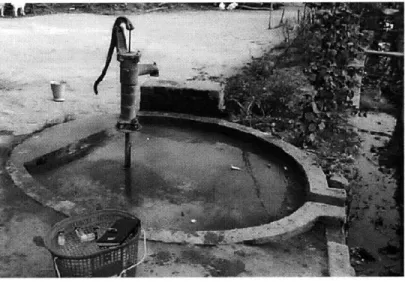
Groundwater is the main source of drinking and irrigation water in most of the Terai region. Therefore, tubewells are widely used to abstract groundwater in the region. A tubewell is a small
Comni ty-lBased Water Supply: TUbewell Program in Lumbini Zone, Nepal
shown in Figure 1-2. There are household (private) tubewells and community (public) tubewells. In the Terai area, on average about 8 households share one public tubewell4*. Some of the private household wells are used by outsiders, too. There has been an effort to install tubewell by various
agencies in Nepal, because:
" Handpumps are among the simplest community water supply technologies. Compared
with electric or diesel pumps, handpumps require substantially less financial resources and easier to maintain.
" Water from a tubewell has been assumed to be of much better quality than water from a
dugwell or surface water such as river water.
Figure 1-2. A Tubewell
FINNIDA* is one of the international aid agencies that have been implementing tubewell
programs in the rural area of Lumbini Zone in Nepal. Through the Rural Water Supply and Sanitation Support Project (RWSSSP), funded by FINNIDA, HMG/Nepal' and the users themselves, FINNIDA has supported 400,000 people to build a water supply and to improve
4 A study on community handpumps in the Terai region by the UNDP-World Bank Water and Sanitation Program
found that the average number of households served by a community handpump was 9 and the average number of people served by a community handpump was 69 (Mudgal, et al., 1995)
* Finish International Development Agency (FINNIDA) is the former name of Department of International
Development Co-operation (DIDC) of Finland. In practice, however, because FINNIDA has become very well known in the field, therefore, the name "FINNIDA" has continued to be used locally, instead of DIDC.
* The majority of the funds was provided by FINNIDA in the first 2 phases. In Phase III, FINNIDA's financial 42%.
Commu 111Ini ty- Based Wateir Supply: Tulewell Program in Lumbini Zone. Nepal
sanitation through Phases I and II of the project during 1990s, and plans to provide an additional
216,000 people with water supply in Phase III (1999-2003)7.
1.4 Project Motivation and Goal
Implementation of tubewell programs has improved the living condition of the rural population
by providing them with better water quality and saving their time spent on fetching water.
However, field tests done by FINNIDA has shown that about 50% of the RWSSSP tubewells tested positive for hydrogen sulfide producing bacteria (referred to as H2S bacteria hereafter).
Past MIT Master of Engineering (MEng) study has also found that total coliform, E.coli and H2S
bacteria were present in the tubewells constructed by the International Buddhist Society (IBS), which is also located in the Lumbini Zone9. Total coliform, E.coli and H2S bacteria are indicator
organisms of fecal contamination in water.
How can groundwater be contaminated with bacteria such as fecal coliform? In most cases, the microbial contamination is caused by unsanitary practices of constructing or using the wells. These practices may include:
1. Sludge drilling which uses cow dung slurry. This is the prevalent method of constructing a tubewell in Nepal.
2. Use of contaminated water to prime the tubewell. Often contaminated water is used to prime the tubewell when the water level in the well is low and suction cannot be created.
3. Inadequate sealing or protection of the well. Some tubewells will have no platform, and
are surrounded by animal sheds and animal waste.
4. Improper drainage that causes accumulation of wastewater in the pit near the well.
5. Flooding during monsoon.
In order to tackle the problem of microbial contamination in tubewells, in January 2002, I went to Butwal, where the RWSSSP office is located. During this visit, a well survey of several Village Development Districts (VDCs) was conducted. Well data, which were collected by RWSSSP for three districts (Kapilvastu, Nawalparasi, Rupandehi), were brought back to MIT.
Conmmuitv-Based 'Water Supply: TubeWe IIProgram in Lumbini Zone,. NepI
preliminary field study of shock chlorination was also conducted to test the suitability of shock chlorination as a way to eliminate microbial contamination in tubewells. These tests and analyses have facilitated the accomplishment of the goal of the project, which is to develop an effective operation and maintenance (O&M) program to prevent future contamination and give recommendation to FINNIDA so their human and financial resources can be better utilized in providing safe drinking water in Nepal.
(ommu nity-Based Water Supply: Tubewell Program in Lumbini Zone, Nepal
2 Tubewells
2.1 History of Tubewells
During the late 70s and early 80s, various problems were observed with the rural water supply systems in developing countries, especially among the poorer sections of the rural population. Many of those systems were mechanized and highly centralized. The problems included the high cost of running these systems, inadequate maintenance, unavailability of spare parts, inability to repair broken units at community levels and thefts of fuel. These problems made people realize that unless more decentralized and more efficient programs were developed, the poor rural population would still be without reliable and convenient water sources. After 7 years of study in
30 countries, a concept called Village Level Operation Maintenance (VLOM) was developed by UNDP and the World Bankl.
The VLOM concept was originally a technological approach to achieve the sustainability objective of rural water supply, based on the use of community managed alternatives, one of the most widely used of which is the handpump. To satisfy this definition of VLOM, a pump would need to be":
" Easily maintained by a village caretaker, requiring minimal skills and a few tools
* Manufactured in-country, primarily to ensure the availability of spare parts * Robust and reliable under field conditions
* Cost effective
Handpumps presented a reliable and affordable water supply option, as they are inexpensive, simple to operate and can be easily adopted in most rural areas in different and conditions.
VLOM rapidly gained its recognition and has been developed into a social, economic, technological concept. The terminology now is extended to Village Level Operation and Maintenance Management (VLOMM). This broader concept also covers the maintenance system
Comniunity-Based Waer SLupply: LIICe11 Program in Lumbini Zone, Nepal
of the pump. Details in different VLOMM projects vary in different areas or countries, but a typical approach would consist of the following components
" Project staff helping villagers form user committees prior to surveying and construction
of the tubewell.
" The committees organizing community labour and contributions to capital costs, and after
construction co-ordinating operation and maintenance, including fund-raising.
" Local leaders and committee members signing a contract with the project agency
specifying the responsibilities of each stakeholder.
* Project staff training designated users in repair and maintenance and providing basic tools, possibly including an initial supply of spare parts.
Based on this VLOMM concept, it was hoped that the villagers would manage the O&M of the program, thereby transforming the social structure of their community, spreading the word among themselves and broadening the scope from water supply to sanitation, and even to other public and economic activities.
However, in reality even with the guidance of the VLOMM concept, many rural water supply programs have failed. The problem of unavailability of spare parts still exists in many remote areas. Users lack the sense of ownership of the pump in some cases, therefore, preventive maintenance is rarely undertaken; and when the pump is actually broken down, no money is collected for repair. RWSSSP's tubewell project will be presented in the following section and the problem with this tubewell program in Nepal will be discussed in detail in Chapters 3 and 5.
2.2 RWSSSP's Tubewell Program
In 1990, FINNIDA started a project in six districts of the Lumbini zone in the Western Development Region to assist HMG/Nepal in providing potable drinking water and sanitation to its population as well as developing facilities for solid and liquid waste disposal system in rural areas. To avoid the problem of duplication, the project was launched in those VDCs, where there were no water supply systems and where other aid agencies were not operating. This project is called Rural Water Supply and Sanitation Support Program (RWSSSP). Today, the RWSSSP has
Cnrnnit y-Based Water Supply: Tubewell Programn in Lwmbini Zone, Nepal
developed into its third phase (Phase III, 1999-2003), which includes a tubewell program, a rainwater collection program and a sanitation facilities (namely latrine) program. The overall objective of RWSSSP Phase III is full coverage of adequate and sustainable water supply and at least 40% coverage of sanitation facilities2.
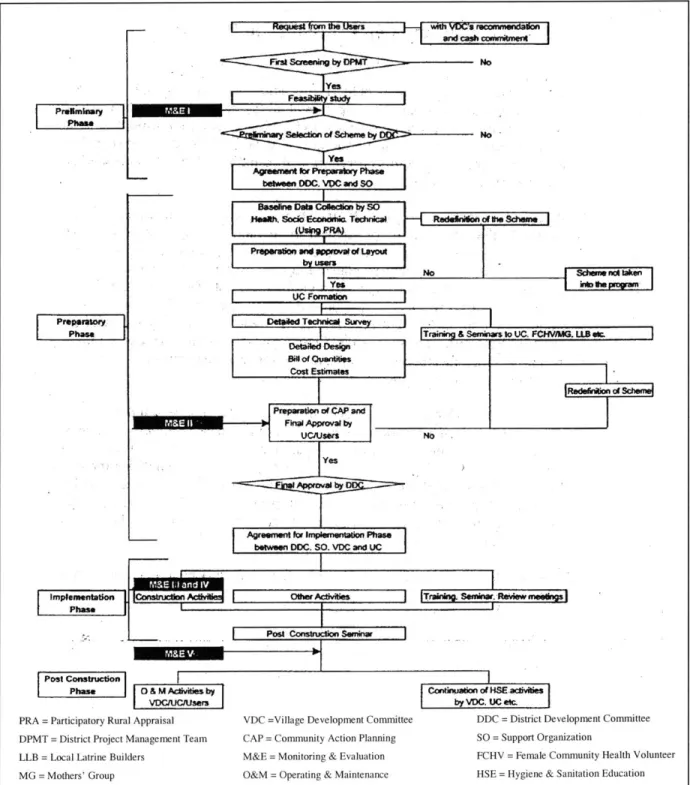
A step-by-step approach is the procedure used in all RWSSSP schemes as shown in
Figure 2-1. It can be summarized as follows8, 13 (a detailed description of the roles and
responsibilities of major stakeholders is shown in Appendix B):
1. Request to RWSSSP for a tubewell comes from the users, with VDC's recommendation and
cash commitment.
2. Approval of the request based on their prioritizing criteria. The criteria include: * Scarcity of drinking water
* Poverty and backwardness of the community
" Distribution of development activities
" Adjoining the VDCs where the tubewell program has been completed
3. Formation of a water users' committee (UC) for the tubewell. A UC, consisting of members
from the households who will be using the well, must be formed to supervise installation, operation and maintenance of the tubewell. Two members (one man and one woman) from each household will join the UC. A Village Maintenance Worker (VMW) will be selected to be responsible for the maintenance of the tubewell.
4. Collection of funds. The UC will collect contributions of NRs 100 to 300 from the beneficiary households. The exact amount of the contribution collected depends on the VDC and the number of households using that tubewell. The UC will also select the site where the well will be constructed based on a field survey and the preference of the users.
5. Seminar and training to UC and VMW. RWSSSP will organize seminars for UC to help them to understand their role and the responsibility, and assist the UC in preparing a Community Action Plan and following it. RWSSSP will also give the VMW a 3-day training course and a tool kit for repairing the handpump.
6. Construction of the tubewell. RWSSSP will provide the handpump, pipe and other
Con1mmUnity-Based Water Supply: Tubewell Program in LuMbInI Zone, Nepal
manner as specified in the Community Action Plan. A Mistri*, who is trained to build wells, will be hired to construct the well, but at least one member from each beneficiary household will come out to help the Mistri.
"''r rom Die hUerS
Iend caete Fira SOeening by DPMT No yes F su Seection of Scheme by No Yes
Ageement for Prepartoy Puse
S beeen DC. VDC and SO
LIe~I*
eseline Daa Cokem, by SO laeeh. Som Ec=ndrn Tedinicai,
lLUin PRAI
I Yes
tiC Formatio
Delpiled Tecnicai Srvey
-DeftdDed i
Co uties
Scheme not taken
bft mpsgrm
Training & Semunws to UC. FCINMGG. U2 etc.
i
fEi+~~nsna~.
No
Preparation of CAP and
Fhnal Approval by
Yes
Agreement ftor impieoentation Phase
between DC. SO. VXC and UC
PP ticiationry Rur AApas D i e FPomt conswr
Post Camtrcto
Phs 0 & M Adivitiks by
PRA = Participatory Rural Appraisal VDC =Village Dev
DPMT = District Project Management Team CAP = Community LLB = Local Latrine Builders M&E = Monitoring
MG = Mothers' Group O&M = Operating
ZiZ I elopment Committee Action Planning & Evaluation & Maintenance Contintod ofHSEcvfties by VDC. UC etc.
DDC = District Development Committee
SO = Support Organization
FCHV = Female Community Health Volunteer
HSE = Hygiene & Sanitation Education
Figure 2-1. RWSSSP Step-by-Step Flow Chart (Source: RWSSSP)
Rdeklln o lt Scheme
SNo
Pniperifto and "Weoarl ou t by m's tinSeminar Wnament i Preemiety Phae I I I I I
Co-nm in ity-Based Water Supp ly: TullbeW Cx Program in Lumbini Zone,. Nepal
7. Regular UC meeting and maintenance. The UC will hold regular meetings to discuss any
issues regarding tubewell or use of the tubewell and ensure services of the VMW to look after the well. The UC will also collect money to establish an Operation and Maintenance Fund and manage the fund properly.
In the RWSSSP model, users are regarded as the managers and owners of the tubewell. Funds collected from the users are put in a bank account of the UC. RWSSSP's role is to facilitate the users in the implementation and management of the tubewell, and conduct trainings and seminars in Health Education and Sanitation (HES) for the users.
2.3 Types of Tubewell in Nepal
Generally, three types of tubewells can be found in Nepal: flowing artesian wells, shallow tubewells with suction handpumps and deep tubewells with lift handpumps.
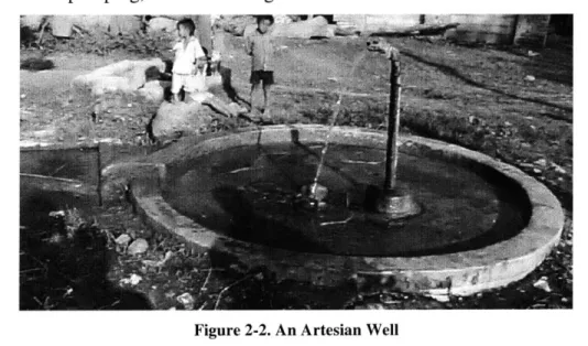
An artesian well is a well in which the water level rises above the top of the confined aquifer4*. In some cases, the water level actually rises above the ground surface, then the well is
,14
known as a "flowing artesian well" .In Nepal, a flowing artesian well equipped with a pipe or a tube is usually referred to as an "artesian tubewell". Water flows out of the tube continuously without the need of pumping, as shown in Figure 2-2.
Cormmunity- Based Water Supply: Tubewell Program in Lan bii Zoie, Nepal
Shallow tubewells are most common in the Teral region. Of the various models of handpumps in use, Nepal No. 2 and No. 4 are smaller in size and commonly used as a household (private) handpump; Nepal No. 6 is larger in size and usually used at the public level . The majority of the tubewells constructed (about 90%) by RWSSSP in the Terai region are shallow tubewells, all of which are No. 6.
A suction handpump mainly consists of a handle, a head cover, a cylinder (pump body),
and a piston (plunger assembly) as shown in Figure 2-3. Figure 2-4 illustrates how a suction handpump works. In Step A, the handle is pressed down to the lowest position, and the piston moves up to the highest position. The upstroke of the piston creates a vacuum inside the cylinder. The pressure inside the cylinder is now lower than atmospheric pressure. Pushed by the air pressure, the water rises to fill the evacuated space. In Step B, the handle is released, the piston moves downward and the water flows through the piston. In Step C, the piston is in the lowest position and starts moving upward. The piston valve is pushed closed and the base valve is opened. In Step D, the piston pushes the water upward while new water enters the pump through the base valve. The cycle starts all over again. Suction handpumps are used to extract water from shallow aquifers. The maximum suction is about 9 meters.
PNE R ND OTBNUT
PUoUDR Wocr a Mur
-HEAD 0
PLATE DOLT
ZED " PPE (PVC PIPE)
Con'iunitv-Based Water SuppIy: Tubewell Program in LUirni Zonie, Nepal
t
A B C D
Figure 2-4. How a Suction Handpump Works
In a lift handpump, the working principle is similar, but the prison assembly is inside a cylinder, which is connected to the handle by a connecting rod, deep down in the borehole. Lift handpumps are used to extract water from deep aquifers. Therefore, tubewells fitted with lift handpumps are referred to as deep tubewells. The lift handpumps used in RWSSSP are India Mark 11/111 as shown in Figure 2-5. Figure 2-6 shows the details of a lift tubewell.
Figure 2-5. A Lift Tubewell
Con minity-Based Water Supply: Tubewell Progran in Lum ibini Zone, Nepal
HANDLE ASEMBLY
HEAD AS(MBLY
1 1 ADOITTONAL F.ANGE
Il
WATOR TANK ASSEMLYSTAND ASSeMBLY h MEWTOC<iE FOUNDATION BE HOLG -CASING COMCT1NG ROD
J
ISER PIPE BORf HOLE .PLJUkER ROo GVYjNEAASEMLY ~- I*0E~ep MATIEG 1EAPPmR VMtvt SP "A -PVAP UCW t fNttlt ...- OmeZA -FeixlRcAr(a) Schematic View (b) Cylinder Assembly
Figure 2-6. Details of a Lift Tubewell (India Mark II)
A tubewell should be sealed with a concrete platform at the base and connected to a
drainage channel, as shown in Figures 1-2 and 2-2. The drainage channel drains off excess water and keeps the surrounding of the platform dry. In a well-constructed platform, the disposal channel drains into a soakage pit, which is a pit dug at the end of the drainage channel and filled with gravel or broken bricks. The pit receives water coming through the channel and keeps the surrounding dry. A platform serves three important purposes:
1. Provide protection against possible groundwater contamination by preventing seepage of
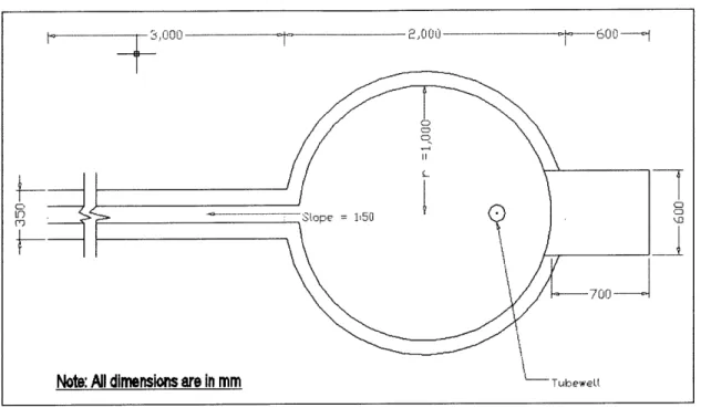
wastewater into the aquifer.
2. Provide a firm and dry operational area for the well users.
3. Prevent lateral movement of the handpump body.
A platform can be circular or rectangular in shape. Figure 2-6 shows the details of a
circular platform.
Community-Based Wate-r Supply: Tubewell Program in Lumbini Zone Nepal
Figure 2-7. Details of a Typical Circular Platform
Deep tubewells cost more to construct than shallow tubewells, because deep tubewells require special drilling equipment. The cost of construction, including slugging, skilled and unskilled labor, pipes, fittings, hand pump and platform, is approximately NRs 10,000 (US$133) for a suction well, and NRs 150,000 (US$200) for a lift well6.
In the RWSSSP coverage area, on average about 8 households share one public tubewell. The advantages of using tubewells are:
* Groundwater is much cleaner than surface water. Tubewells are sealed to protect the source, therefore, they are better than dugwells, which are often not covered.
* Handpumps do not require electricity or fuel to be powered, therefore, are easier to use and maintain than electric or diesel pumps. Compared with electric or diesel pumps, hand pumps require substantially less financial resources.
a2
1 0ooo-
--1 0.0 0~
CD
.. . D
UbkeWEIA
Note: All dimensions are in mm
----
Communi ty-Based Water Supply: Tubvewell Program in Lumbini Zone, Nep'Al
3 Contamination Problem
3.1 Problem Statement
Despite the benefits that tubewells offer and the effort by various NGOs to install tubewells in Nepal, there appears to be a microbial contamination problem with tubewell water. Over the past two years, RWSSSP has been conducting water quality monitoring of their wells using the H2S
bacteria Presence/Absence (P/A) test, and has found that about 50% of the water sample taken from tubewells showed the presence of H2S bacteria in Lumbini Zone. H2S bacteria are indicator
organisms of fecal contamination; their presence indicates the possible presence of pathogens of fecal origin, which can causes illnesses such as diarrhea. Generally, the microbial contamination is caused by unsanitary practices of constructing or using the wells. These practices may include:
" Sludge drilling which uses cow dung slurry. This has been the prevalent method of
constructing tubewells in Nepal. However, recently after suspecting cow dung might be one of the factors that causes contamination, RWSSSP started substituting bentonite for cow dung to build tubewells.
" Using contaminated water to prime the well. Often dirty external water is used to prime
the well when the water level in the well is low and suction cannot be created. In a UNDP-World Bank handpump study, it was found that 42% of the No.6 handpumps required priming, and almost 15% to 20% of the sampled handpumps required priming
15
before every use
* Inadequate sealing or protection of the well. Some tubewells have no platform or a broken platform, and are surrounded by domesticated animals and animal waste. Animals can walk around the well freely, they might introduce bacteria to the mouth of the handpump through contact.
" Some tubewells are built near latrines or animal sheds. The nearer the tubewell is built to
a latrine or an animal shed, the higher the risk of contaminated water percolating into the well.
* Improper drainage that causes accumulation of wastewater in the platform or the pit near the well.
COMmunity-Based Watei SLIpy v: Tubewell Programn in Lumbini Zone, Nepal
During the visit to Nepal in January 2002, a survey of 45 tubewells was conducted in Lumbini Zone. Well data, which were collected by RWSSSP in the past two years for three districts (Kapilvastu, Nawalparasi, Rupandehi), were brought back to MIT. Analysis was performed on the data to determine the causes of the microbial contamination. A preliminary field study of shock chlorination was also conducted to test the suitability of shock chlorination as a way to eliminate microorganisms in tubewells. The overall goal of this thesis research is to develop an effective operation and maintenance program for tubewells
3.2 H
2S Bacteria P/A Test
As discussed before, H2S bacteria are a type of indicator organism. H2S bacteria test has the
following advantages1:
* It requires simple ingredients that are readily available in developing countries.
" The growth medium is in the form of a dried paper strip, which can be safely stored at
room temperature for at least 6 months.
" The test can be carried out without the use of an incubator or other special laboratory
equipment.
* The black positive reaction is easy to read.
" Even untrained personnel can reliably carry out this test because of its simplicity.
H2S bacteria P/A test is the method used by RWSSSP to monitor the microbial quality of
the tubewell water. Tubewell water samples are collected and left in 20-ml bottles that contain the H2S bacteria medium for 48 to 72 hours at room temperature (22-30*C). The water will turn
black if it contains H2S bacteria; otherwise the colour will not change. RWSSSP bought the H2S
bacteria medium from ENPHO, a Non-Governmental Organization (NGO) that provides environmental services and is based in Kathmandu. ENPHO prepared the medium in a 20-ml capped bottle to RWSSSP. For this reason, 150 bottles of H2S bacteria medium were prepared at
MIT and brought to Nepal for my own microbial testing (see Appendix D for the list of ingredients and the procedure of preparing H2S bacteria medium).
Commn flity-Based WatCr SuPtply: Tubewell. Prograrn in Lumbini Zone, Nepal
3.3 Field Work
3.3.1 Water Quality Testing
To confirm the extent of the microbial contamination in Lumbini Zone, I conducted water quality testing using the H2S bacteria P/A test. The testing procedure is described below:
1. Washed hands with antibacterial soap before sampling.
2. Put the bottle containing the H2S bacteria medium under the tubewell spout to collect the
water. Put the sample bottle in a closed container after the water was collected. Sometimes, when water could not be pumped from the well, externally procured water was added into the handpump to prime the well. In this case, because the microbial quality of the externally procured water was unknown. The water sample was collected after the well was pumped and water was allowed to flow out for five minutes.
3. Two sets of sample were collected for each tubewell tested. One set was left at ambient
temperature with no incubation, the other set was put in a phase-change incubator, invented by Amy Smith at MIT, to determine if incubation was necessary during the coldest month of January in the Terai Region with the H2S P/A test. The phase-change
incubator is capable of maintaining a constant temperature of 37 'C for 24 hours. All samples were discarded after 72 hours.
Precautions were taken to minimize the possibility of cross contamination or contamination through handling; it is unlikely that the sampling procedure contributed to any finding of microbial contamination in tubewell water.
3.3.2 Results of Incubation vs. Non-Incubation of H2S Bacteria Test
Generally if the well was contaminated, it was found that incubation in the phase-change incubator made the sample turn back faster than that without incubation. The non-incubated sample would still turn black eventually within those 72 hours. The time gap between when an incubated sample turned black and when its non-incubated counterpart turned black was 20 to 24 hours. Therefore, incubation of the H2S bacteria test in the phase-change incubator was not
(oIn MMUnity-Based Water SIpplV: Tubhewell Program in LuMNbi ni Zone, NeCpal
reaction time. Seventy-two hours were an appropriate (long enough) amount of time to develop a color change if the water contained H2S bacteria under ambient air conditions, which ranged
from about 15 to 25 *C in Nepal.
As a result, 19 out of the 45 wells tested were found to be positive with H2S bacteria, i.e.,
42% of the samples*. This finding generally agrees with RWSSSP's finding of 50% of wells contaminated with H2S bacteria.
3.3.3 Inspection of Tubewells
Inspection of tubewells was also conducted along with water quality testing. Fifty tubewells were inspected, 45 of which were sampled used in the water quality testing mentioned above. The following are some of the major problems identified.
First, some of the platforms were in bad condition in which case, dirty water could infiltrate into the well. Second, some handpumps were broken- nuts and bolts were missing- but no repair was to be carried out. A rope or an iron wire would be used to replace the missing nuts or bolts. Mud would be used to fill the cracks on a pump body to stop leaking. A broken handpump is not water-tight, therefore, bacteria can get into the well. Figure 3-1 shows an example of a broken platform and an example of a broken handpump. Third, in some cases, the users were not concerned about these problems, since the well was "working" anyway. Fourth, in some other cases, the users reported the breakdown to the user committee, but the user committee just ignored the problem, or no funds were available to fix the problem. This is a clear indication of inadequate maintenance.
In summary, four major problems were identified during the inspection of tubewells. They are:
1. Platforms in bad condition leading to wastewater infiltration.
2. Broken handpumps.
Comnnflitly-Based. Wate-r Supply: Tubewell- ProgrM in Lmiii ibni l Zone, Nepal
4. User committees that ignored tubewell problems.
Figure 3-1. A Broken Platform and A Broken Handpump
3.4 Data Analysis
Data for 163 wells were analyzed to determine the possible causes of the microbial contamination. These data were collected by RWSSSP staff in the past two years as part of their own well survey and are shown in Appendix F. These 163 wells include the 45 wells mentioned in Section 3.3.1. The average depth of those 163 wells is 27 meters and the average age is 6 years. Six parameters, which might be the causes for the microbial contamination of the wells, have been investigated. These parameters are:
1. Number of users (people using the well) per well 2. Age of the wells
3. Distance to the nearby latrine
4. Distance to the nearby anima shed
5. Depth of the wells
6. Use of cow dung as slurry in the construction of tubewells
Each parameter is divided into "bins". For example, for the numbers of users parameter, the bin is 10 users per well (0-9, 10-19, 20-29, and so on until the last bin, which is 1440-1450). The number of H2S bacteria contaminated wells and uncontaminated wells is counted for each
(omm unity-Based Water SIpply: Tubewell Program in LLm binii Zonie, Nepal
bin and the percentage of contaminated wells within that bin is calculated. Figures 3-2 to 3-5 show the results of the analysis of the first four parameters graphically.
100% 2 80% 0 60%H ?'0 100.0% 100.0%100.0% 100.0% E40% 7 7 75% 818%7 750 66.7% 66.7% 621% H 7% 20% - 456% 42.9% 0% 0) 0) 0) 0M 0M 0M 0) 0) 0) 0) 0) 0) a) 0) 0) 0) a) 0) 0) 0 i 3-2 PC ) ( te- C D0 0 We s Nb O U er 0 0 O 6 N I I I I I~ I U 0 0 0 0 0 0 0 0 06 NQ CO I' UO CD r- 0CM 0 6 0 0 0 0 0 0 0 0 6 0 ~ N N \ U) O O 0 N\ 0 0 N\ N4 Cf) 't 't UO) Users/Well
Figure 3-2. Percentage of H2S Bacteria Contaminated Wells vs. Number of Users per Well
100% 80% UM)- -0 60% E
H100.0%
40%.. 58.5% 0 20% 42.9%1
.25.0% 0.0% 11.1% 0.0% 0.0% 0.0% 0.0% 0% -0.042 1 2 3 4 5 6 7 8 10 11 15 22Age of the Well (yr)
Comm.Unity-BaseI Water Supp.ly: Tub ewell Program in LUmbini Zone, Nepal 100%-80% -60% -40% -20% - 50.0% 50.0% 0.0% 35-39 40-44 45-49
Figure 3-4. Percentage of H2S Bacteria Contaminated Wells vs. Distance to Latrine
100.0% 750%
[1
63.6%[]
[1
33.3%/ 37.5% 33.3%A1/ I
1-5 6-10 11-15 16-20 21-25 26-30 31-35 Distance to Latrine (m) 833% 50.00/ 36-40 41-45 667% 46-50 > 50Figure 3-5. Percentage of 112S Bacteria Contaminated Wells vs. Distance to Animal Shed
Figures 3-2 to 3-5 show that the first four parameters do not contribute to the H2S
bacteria contamination- the percentage of contaminated wells varies randomly as the values of the parameters increase. These random changes in the percentage of contaminated wells imply that the first four parameters are very unlikely to be the causes of the contamination.
Figure 3-6 shows the analytical result for the fifth parameter. It seems that there is a slight trend of reduction in the percentage of H2S bacteria contamination as the depth of well
18
decreases. In 1991, FINNIDA commissioned a groundwater resource study' .It was found in the study that most of the tubewells withdrew water from the topmost aquifer (first layer) for
75.0%
625%
54.5% 57.1% I
5-9 10-14 15-19 20-24 25-29 30-34
Distance to Animal Shed (m) E 0 0 42.9% 0-4 0%-> 50 100%- 80%- 60%- 40%-20% -E 0 C.)
H50.0%
V
I
0% 04.'-1*Corn i ity-Based Water Suppiy: Tubewell Program in Lumbini Zone, Nepal
domestic use. The water redrawn from this aquifer was not microbially safe, because direct percolation of wastewater from the surface was high. For this reason, RWSSSP has been constructing tubewells, which withdraw water from the second aquifer, 18 to 69 meters deep 9. it was also found that the actual depth of the aquifer differed from place to place.
100% - 80%-60% .~40%-11111 7 . 0 % 634.6%0 704 57.9%6.%5.% 5. 20%44 1 o 20%34.8% 2 1 M% 33.3% 0% In 0 In OI 0 LO L 0 LO 0 0 InO 0? T- T N N~ t q IOn L CD CD N n 0 In 0 In 0 In 0 In In 0 L6 C1 C\ CO~ It IOIt (0 (0
Depth of the Well (m) 0.0%
Figure 3-6. Percentage of H2S Bacteria Contaminated Wells vs. Depth of the Well
Because all RWSSSP tubewells are constructed into the second aquifer, it will take a long time (on the order of years) for the contaminated surface water to travel from the surface to the aquifer. Bacteria will have died out within that period. Therefore, even though one might assume that the nearer a tubewell is to a latrine or a animal shed, the higher the risk of contamination there would be, the data analysis of these two parameters shows that the distance to latrines or to animal sheds do not contribute to the problem of contamination. Nevertheless, it is still good practice not to build the wells near latrines and animal sheds, because the foundation or platform of the well may be damaged and dirty water that leaks from the latrine or animal sheds may percolate through the soil and reach the second aquifer.
Table 3-1 shows the numbers of tubewells that were constructed with and without cow dung within that 163 well data set. It also shows how many of these wells were found to be contaminated with H2S bacteria. The result is also shown graphically in Figure 3-7. As seen from
the figure, there is an increase in the percentage of contaminated wells "with cow dung" compared to "without cow dung" to (17.8% increase). This indicates that the use of cow dung in
ConnMmunity-Based Water Supp ly: TuLe Cwell Program in LuImbini Zone, Nepal
Table 3-1. Use of Cow Dung in Construction
Number of Wells
Not Contaminated 17
Without Cow DungCotmned1
Contaminated 11
With Cow Dung Not Contaminated 58
Contaminated 77 90 ___ 0 C 3 Not Contaminated 70 C *60 50 0 30 20 10 0
Without Cow Dung With Cow Dung
Cow Dung Use
60% --.-5 10% 40% j 30% -570 9 0 20% 0 10%r 0%
Without Cow Dung With Cow Dung
Cow Dung Use
Figure 3-7. Level of H2S Bateria Contamination vs. Use of Cow Dung
Using cow dung is a traditional way of building tubewells in Nepal. The primary concern with using cow dung is not primarily the fecal pathogens in the cow dung, because fecal pathogens will die out quickly after leaving their host. How long pathogens remain viable in water after they leave their host varies with the species. Typically, the pathogens lose their viability and ability to infect exponentially with time. Hence, cow dung will not affect the microbial quality of the well water in long term. In her microbial water quality survey in Lumbini, Nepal, MiEng student Hannah Sullivan found that wells that were constructed with cow dung just several days prior to sampling show extremely elevated level of contamination by fecal
20
(oiunity-Based Water SpIlylv: Tubewell Program in LUmbini Zone, N epal
Sullivan suggests that these elevated levels of contamination are due to the use of cow dung slurry in well construction, but are not indicative of long-term contamination, because "the highest level of contamination found in wells older than one month was 14 CFU/100 ml, indicating that contamination from the use of cow dung slurry does not persist in tubewells water longer than one month after well construction is completed". However, the main problem is that cow dung is mainly organic matter, which will disintegrate over time. The wells may have cracks and holes around the PVC pipe underneath the platform, resulting in short circuiting of wastewater there. The empty space can store dirty water, which in turn may seep into the tubewell, contaminating the groundwater. It is recommended that the condition underneath the platform of tubewells constructed with cow dung should be investigated, either by conducting a dye test or digging the platform up to examine the extent of the disintegration.
Many of RWSSSP's tubewell were constructed using cow dung. However, recently RWSSSP has stopped using cow dung and used bentonite instead in building new tubewells. Nevertheless, all the tubewells should be disinfected after construction and before use, because contamination can be introduced to the water through other means in the construction process. The disinfecting method is called shock chlorination, which will be discussed in later chapter.
Field observations and literature review also suggest that other causes of microbial contamination could be floodwater during monsoon, priming of the well with dirty external water, free access of animals to the wells and inappropriate maintenance of the wells.
C.ommunity-Based W\ater SuppI y: TLubeVefl Prograi in Lumbini Zone, Nepal
4 Shock Chlorination
4.1 Chemistry of Shock Chlorination
Shock chlorination is the one-time introduction of a strong chlorine solution into a water distribution system (well, pump, distribution pipeline, hot water heater, etc.). It is a relatively inexpensive and straightforward disinfection method to eliminate microorganisms such as iron bacteria, sulfate-reducing bacteria, fecal coliforms, and pathogens in wells. Shock chlorination should be recommended:
" When water monitoring indicates the presence of bacteria in a well.
* Upon completion of a new well.
" After repair of an existing well.
* Following contamination by flood water.
Bacteria may be introduced during drilling of a well or when pumps are removed for repair and laid on the ground. However, some bacteria can exist naturally in groundwater. A well creates a direct path for oxygen to travel into the ground where it would not normally exist. When a well is pumped, the water flowing in will also bring in nutrients that enhance bacterial
21
growth
Chlorine destroys microorganisms by penetrating their cell walls and neutralizing the enzymes that are essential for their survival22, 23. When a large amount of chlorine, either in a
liquid compound or a solid compound, is applied into the well, the following reactions take
place2:
" First, it combines with inorganic compounds (hydrogen sulfide, ferrous iron, manganese);
there is no disinfection at this stage.
" The remaining chlorine then reacts with organic matter (algae, phenols and slime
growth). While some bad tastes and odours may be eliminated, there is only a slight disinfection action and trihalomethanes, which are carcinogenic, chlorinated organics, may be formed.
Connumitv-Based Water Supply: Tubewell Program in Lumbini Zoe, Nepal
* After the demand exerted by inorganic and organic matter has been met, chlorine will combine with nitrogen compounds (primarily ammonia) to form chloramines. This combined residual chlorine form results in long lasting disinfection, produces minimal chlorine taste or odour and controls organic growths.
* Finally, once even more chlorine is added to the water, the chloramines are destroyed and excessive chlorine, known as the free residual, forms hypochlorous acid (HOCL), which is a potent, fast reacting disinfectant. Free chlorine can prevent the growth of bacteria in the water system .The adequate free chlorine residual level is in the range between 0.2 mg/L and 0.5 mg/L, as defined by the World Health Organization (WHO).
The effectiveness of shock chlorination depends on the following factors:
* Extent of the microbial contamination. If there are large numbers of aerobic or anaerobic bacteria in the water, a high chlorine dosage is required to ensure that all disease causing
organisms have been destroyed.
* pH. Hypochlorous acid will dissociate into hydrogen (H+) and hypochlorite (OCV-) ions. Hypochlorite is 80 to 250 times less effective as a disinfectant than HOC. The higher the
pH, the more dissociation will occur. At pH of 5 almost all of the chlorine residual is in HOCl form, at pH of 9, almost all of the residual is in OCl- form. Hence, WHO
recommends that for effective disinfection the pH of the water needs to be below 8. * Temperature. Temperature affects the rate of disinfection- usually the higher the
22
temperature, the faster the rate of disinfection
* Turbidity. Disinfection of bacteria will only begin after the chlorine demand exerted by turbidity (inorganic and organic compounds) is met. In addition, chlorine is a surface-active agent so it cannot effectively penetrate into solids to kill the concealed bacteria. In established municipal water treatment systems, water is filtered to remove turbidity prior to chlorination; but this is not feasible for the tubewell systems in Nepal. New wells often have turbid water that contains elevated concentrations of iron and organic slimes. As a result, much higher chlorine doses are required to shock chlorinate new wells. More importantly, new wells must be effectively developed prior to disinfection since the presence of organics (including residual drilling fluid) and fine particulate matter can
Co(mn ity- Based WaIter Spiy: Tubewel] Program n Lumibinll Zonie, Nepal
make disinfection ineffective and can result in the formation of compounds that have unacceptable health or aesthetic characteristics.
4.2 Procedure of Shock Chlorination
The general procedure of shock chlorination is:
1. Determine the depth of water in the well, L. For example, if you have a 20-meter deep well,
and the water level is at 10 meters, the well contains 10 meters of water (20 -10 = 10 meter).
2. Calculate the volume of water, V, to be treated. The volume of water is equal to the depth of water in the well multiplied by the cross sectional area, A, of the well. Mathematically, this can be expressed as:
V=LxA=LxxD 4 where D = the diameter of the well.
3. Determine how much chlorine needs to be added to effectively disinfect the calculated
volume of water. Newly constructed wells should be chlorinated with 250 milligrams of available chlorine per liter of water (250 mg/L) 23
For example, if the volume of the water, V, that you calculate from the above formula is 0.05
m3 (50 L), and the concentration of chlorine that you need is 250 mg/L, then the amount of
chlorine that you need is 12,500 milligrams (12.5 g). If the disinfectant being used is bleaching powder with 70% strength4, then the amount of bleaching powder that you need is
17.8 g.
If sodium hypochlorite is used, just pour the chlorine into the well. If calcium hypochlorite is
used, dissolve the chlorine powder or tablets in a 20-liter (5-gallon) bucket of water before adding it to the well. Be sure the bucket is plastic and has been thoroughly washed. Add no more than 100 g of calcium hypochlorite to each bucket. When mixed with water, an insoluble residue will likely be formed. This residue should be allowed to settle and the clear
Comm11unity-Based 'Water Supply: Tubewe11 Program in Lumbini Zoie, Nepal
supernatant containing the chlorine should be decanted. Pour the clear solution into the well2.
If possible, agitate the water to evenly mix the chlorine. This will thoroughly mix the
chlorine solution and well water. For instance, lower a rope, to which a stone is attached, into the well and move it up and down; Figure 4-1 shows a schematic of the application of shock chlorination.
5ophon hose Chlorine
Wel
[
Treatment zoneAquifer
Coppright %) ZWu
AIberta Acirlume Food d eloment
Figure 4-1. Siphoning Chlorine Solution
4. Leave the chlorine solution in the well for at least 12 hours and preferably for 24. After 12-24 hours, pump the strongly chlorinated water out of the well. The pump will be disinfected by using it to remove the excess chlorine. Choose a disposal place, where contact with plant and animal life is minimal, for the chlorine solution. Distribute the wastewater on gravel roads or other areas without plants or aquatic life.
If a chlorine smell is not present in the discharge water after this contact time, the
Ciomnunity-Basecd Water Supply: Tubewell Program in Lumbini Zone, Nepal
5. Discharge the water in the system to waste until the smell of chlorine disappears. Some
chlorine may persist in the system for 7-10 days. The amount of chlorine remaining in the water will not be harmful. In about a week, collect a water sample for bacteriological examination. Two consecutive "safe" tests will probably indicate that the treatment has been effective.
If tests show continuing bacteriological contamination, a second shock chlorination is
recommended. If the water supply continues to develop microbial contamination problems after being shock chlorinated, regular, frequent chlorination may be necessary, although this may be a burdensome expense for aid organizations or user committees. Other options include repairing the well, constructing a new well or abandoning the water source if necessary.
4.3 Safety Practices and Health Concerns
Chlorine is a very reactive substance. It is corrosive and can even be deadly. Safety practices are needed in order to handle chlorine and apply shock chlorination safely. Before beginning the shock chlorination process, you should store ample clean water in a big container. If concentrated chlorine accidentally comes in contact with your eyes or skin, use this clean water to flush the affected area for 10-15 minutes. If chlorine solution gets into your eyes, see a doctor after thoroughly flushing the affected eye.
A second safety practice is to wear appropriate safety clothing and equipment. Wear
goggles to avoid contact with the strong chlorine material and your eyes. Wear a pair of rubber gloves to protect your hands and shoes and long pants to totally cover your toes and feet. To prevent discoloration of your clothing, wear a waterproof suit, coveralls, old clothing or a
full-length apron.
Remember that chlorine is very volatile so it is dangerous to work with in confined areas. Make sure the work area is well ventilated. Care must be taken when mixing and adding chlorine to a well since exposure to it can result in severe skin or eye irritations and blisters. It is also