RESEARCH OUTPUTS / RÉSULTATS DE RECHERCHE
Author(s) - Auteur(s) :
Publication date - Date de publication :
Permanent link - Permalien :
Rights / License - Licence de droit d’auteur :
Bibliothèque Universitaire Moretus Plantin
Institutional Repository - Research Portal
Dépôt Institutionnel - Portail de la Recherche
researchportal.unamur.be
University of Namur
Engineering Configuration Graphical User Interfaces from Variability Models
Boucher, Quentin; Perrouin, Gilles; Davril, Jean-Marc; Heymans, Patrick
Published in:
Human Centered Software Product Lines
Publication date:
2017
Document Version
Peer reviewed version
Link to publication
Citation for pulished version (HARVARD):
Boucher, Q, Perrouin, G, Davril, J-M & Heymans, P 2017, Engineering Configuration Graphical User Interfaces from Variability Models. in J-S Sottet, AG Frey & J Vanderdonckt (eds), Human Centered Software Product
Lines. Springer, pp. 1-46.
General rights
Copyright and moral rights for the publications made accessible in the public portal are retained by the authors and/or other copyright owners and it is a condition of accessing publications that users recognise and abide by the legal requirements associated with these rights. • Users may download and print one copy of any publication from the public portal for the purpose of private study or research. • You may not further distribute the material or use it for any profit-making activity or commercial gain
• You may freely distribute the URL identifying the publication in the public portal ?
Take down policy
If you believe that this document breaches copyright please contact us providing details, and we will remove access to the work immediately and investigate your claim.
Interfaces from Variability Models
Quentin Boucher, Gilles Perrouin, Jean-Marc Davril, and Patrick Heymans
Abstract In the past, companies produced large amounts of products through mass production lines. Advantages of such an approach are reduced production costs and time-to-market. While it is (still) appropriate for some goods like food or household items, customer preferences evolve to customised products. In a more and more competitive environment, product customisation is taken to the extreme by compa-nies in order to gain market share. Compacompa-nies provide customisation tools, more commonly called product configurators, to assist their staff and customers in decid-ing upon the characteristics of the product to be delivered.
Our experience reveals that some existing configurators are implemented in an ad-hocfashion. This is especially cumbersome when numerous and non-trivial con-straints have to be dealt with. For instance, we have observed in two industrial cases that relationships between configuration options are hard-coded and mixed with GUI code. As constraints are scattered in the source code, severe maintenance issues occur.
In this chapter, we present a pragmatic and model-driven way to generate figuration GUIs. We rely on feature models to represent and reason about the con-figuration options and their complex relationships. Once feature models have been elaborated, there is still a need to produce a GUI, including the integration with underlying reasoning mechanisms to control and update the GUI elements. We present a model-view-presenter architecture to design configurators, which sepa-rates concerns between a feature model (configuration option modelling), its asso-ciated solver (automated reasoning support) and the presentation of the GUI. To fill the gap between feature models and configuration GUIs, the various constructs of the feature model formalism are rendered as GUI elements through model
trans-Quentin Boucher,
CETIC, Avenue Jean Mermoz, 28, 6041, Charleroi, Belgium e-mail: [email protected]
Gilles Perrouin, Jean-Marc Davril, and Patrick Heymans
PReCISE Research Centre, University of Namur, Rue Grandgagnage 21, 5000 Namur, Belgium e-mail: [email protected]
formations. Those transformations can be parametrised through beautification and view languages to derive specific configuration GUIs. We illustrate our approach on an IPv6 addressing plan configurator.
1 Introduction
In the past, companies produced large amounts of products through mass produc-tion lines. Advantages of such an approach are reduced producproduc-tion costs and time-to-market. While it is (still) appropriate for some goods like food or household items, customer preferences evolve to customised products. Even car production which was a major example of mass production has moved to the customisation cat-egory. Henry Ford played a pioneering role in the mass production of cars. Fordism aimed to achieve higher productivity by standardizing the output, breaking the work into small well specified tasks, and using conveyor assembly lines. However, Ford’s quote “Any customer can have a car painted any colour that he wants so long as it is black” already illustrates the limitations of mass production, back in 1923.
In a more and more competitive environment, product customisation is taken to the extreme by companies in order to gain market share. Companies provide cus-tomisation tools, more commonly called product configurators, to assist their staff and customers in deciding upon the characteristics of the product to be delivered. This trend is further strengthened by the ever-growing presence of such configura-tors on the Internet.
The key idea behind configurators is to provide end-users with an easy-to-use Graphical User Interface (GUI) where they can select the desired options and cus-tomise their product. The result of the configuration is then used by the manufacturer in order to produce the final product with the required options. Generally, the user is guided by the GUI in her process. That guidance manifests itself in different ways. First, configuration can be broken down into steps. Typically, a step represents a set of logically linked configuration options. That set depends on different param-eters such as user requirements, application domain, etc. Constraint verification is another guidance mechanism. Selecting an option might, for example, require the inclusion or exclusion of another one. Many more constraints examples are available around us. Configurators should preclude inconsistent activation or deactivation of configuration options to avoid frustration on the user side and technically unrealistic products on the manufacturer side. Furthermore, constraints are of different natures. Some are of technical nature while others originate from business rules. Both may change over time.
Our experience reveals that some of those existing configurators are implemented in an ad-hoc fashion. This is especially cumbersome when numerous and non-trivial constraints have to be dealt with. For instance, we have observed in two indus-trial cases [47] that relationships between configuration options are hard-coded and mixed with GUI code. In other words, the configuration logic is not separated from the rest of the application code. As constraints are scattered in the source code,
se-vere maintenance issues occur. For example, engineers are likely to introduce errors when updating or adding new constraints between options in the configurator. More-over, as recognized by our industrial partners developing such configurators, the correctness and the efficiency of the reasoning operations are not guaranteed. More reliable and maintainable solutions are thus needed, especially for safety-critical systems.
We propose a pragmatic and model-driven way to generate configuration GUIs [18]. We rely on Feature Models (FMs) to represent and reason about the configura-tion opconfigura-tions and their complex relaconfigura-tionships. FMs have been extensively studied in academia during the last two decades, primarily in the software product line com-munity [53]. FMs are now equipped with formal semantics [80], automated reason-ing operations and benchmarks [4, 12], tools [7, 14, 55] and languages [9, 24]. In essence, an FM aims at defining legal combinations of features authorised or sup-ported by a system. In our case, configuration options are modelled as features and each configuration (specification of a product) authorised by the configurator cor-responds to a valid combination of features in an FM. A strength of FMs is that state-of-the-art reasoning techniques, based on solvers (e.g., SAT, SMT, CSP), can be reused to implement decision verification, propagation, and auto-completion in a rigorous and efficient way [9, 12, 50]. Therefore FMs are a very good candidate to pilot the configuration process during which customers decide which features are included in a product.
Once FMs have been elaborated, there is still need to produce a GUI, includ-ing the integration of underlyinclud-ing reasoninclud-ing mechanisms to control and update the GUI elements. On the one hand, some FM-based configuration GUIs rely on solvers [7, 14, 55]. But such GUIs do not consider presentation concerns and their generation process is rigid, avoiding the derivation of customised GUIs [44]. Fur-thermore existing graphical representations of FMs (e.g., FODA-like notation or tree-views) are not adapted to user-friendly configuration [70]. On the other hand, model-based approaches for generating GUIs simply produce the visual aspects of a GUI [15, 16, 26, 43]. This is not sufficient for configurators since constraint veri-fication is paramount for their usability and performance.
Our approach is to combine the best of both worlds, i.e., correct configurations together with user-friendly generated GUIs. We present a model-view-presenter (MVP) architecture to design configurators, which separates concerns between an FM (configuration option modelling), its associated solver (automated reasoning support) and the presentation of the GUI. To fill the gap between FMs and con-figuration GUIs, the different constructs of the FM formalism are rendered as GUI elements through model transformations. The transformations are based on a meta-model for TVL [20, 24], a textual language for feature meta-modelling. Transformations can be parametrised through beautification and view languages to derive specific configuration GUIs.
The rest of the chapter is organized as follows. First, in Section 2 we give some background information about feature models and GUIs. The existing work link-ing feature models and GUIs is also addressed. In Section 3, an overview of our approach is proposed. Then, in Section 4, we present the implementation of the
ap-proach. It includes three different languages as well as a Web configurator generator. All the concepts are illustrated with throughout an IPv6 addressing plan configura-tion example. Finally, before concluding, we present the lessons learned in Secconfigura-tion 5 and discuss some perspectives to our work in Section 6.
This book chapter is essentially based on a PhD thesis presented by the first author in September 2014 at the University of Namur (Belgium). For more detailed information about the approach, the interested reader may refer to [18].
2 Background
Here, we introduce the background required to understand the contents of this chap-ter as well as existing approaches that we compare to ours. Feature models being the starting point endeavour, we introduce them in Section 2.1. Then, in Section 2.2, we introduce UI-related concepts and generation.
2.1 Feature Modelling
Software Product Line Engineering (SPLE) is an increasingly popular software en-gineering paradigm which advocates systematic reuse across the software lifecycle. Central to the SPLE paradigm is the modelling and management of variability, i.e., “the commonalities and differences in the applications in terms of requirements, ar-chitecture, components, and test artefacts”[71]. Variability is typically expressed in terms of features, i.e., first-class abstractions that shape the reasoning of the en-gineers and other stakeholders [25].
Feature models were introduced as part of the FODA (Feature Oriented Domain Analysis) method 25 years ago [53]. They were introduced as graphical notations whose purpose is to document variability. Since their introduction, FMs have been extended and formalised in various ways [30, 80] and tool support has been pro-gressively developed [42]. The majority of these extensions are variants of FODA’s original tree-based graphical notation.
Graphical FM notations based on FODA [53] are by far the most widely used. Most of the subsequent proposals such as FeatuRSEB [45], FORM [54] or Genera-tive Programming [29] are only slightly different from the original graphical syntax (e.g., by adding boxes around feature names).
A number of textual FM languages were also proposed in the literature. Table 1 compares them against the following criteria: (i) human readability, i.e., whether the language is meant to be read and written by humans; (ii) support for attributes; (iii) decomposition (group) cardinalities; (iv) basic constraints, i.e., requires, ex-cludesand other Boolean constraints on the presence of features; (v) complex con-straints, i.e., Boolean constraints involving values of attributes; (vi) mechanisms for
structuring and organising the information contained in an FM (other than the FM hierarchy); (vii) formal and tool-independent semantics, and (vii) tool support.
Table 1: Existing textual variability modelling languages
Language Human readable Attrib utes Cardinalities Basic Const. Complex Const. Structuring Formal semantics T ool support FDL [32] X X X FMP [7] X X X X X GUIDSL [9]X X X FAMA [13] X X X X X pure::variants [14] X X X X X SXFM [61]X X X VSL [78] X X X X X KConfig1 X X X X X
We should note that all these languages are remotely related to constraint pro-gramming, and several implementations use constraint solvers internally. Moreover, as pointed out by Batory [9], FMs can be seen as simplified grammars where prod-ucts correspond to sentences. Similarly, FMs with attributes can be seen as a form of attribute grammar, albeit without the distinction of synthesised or inherited at-tribute [56, 8]. What distinguishes FMs from constraint programming and atat-tribute grammars is their domain-specific nature and independence from any of these tech-nologies.
2.2 User Interface Modelling and Generation
This section is decomposed into two sub-sections. In the first one, we give a short description of major user interface description languages which could be used as tar-get languages for our generation approach. In the second, existing work combining variability models (more exactly FMs) and GUIs is presented.
2.2.1 User Interface Description Languages
In the Human-Computer Interaction (HCI) research domain, automation of UI de-velopment is an important topic. A whole spectrum of approaches ranging from purely manual design to completely automated approaches have been proposed.
Manual design is of no interest to us as we seek to automate the generation of in-terfaces. On the other hand, fully automated approaches generate moderately usable GUIs, except for domain specific applications [65].
Most approaches propose a partially automated process which uses extra in-formation about the UI stored in models. They are all grouped under the Model-based User Interface Development (MBUID) denomination, generally supported by an MBUID environment (MBUIDE). It can be defined as “a suite of software tools that support designing and developing UIs by creating interface models”[43]. Each MBUIDE defines its own set of models to describe the interface. The different MBUIDEs and the associated models have been surveyed by Gomaa et al. [43] and the W3C [87]. Here, we give a summary of User Interface Description Languages (UIDLs) used in MBUID. XML-based UIDLs have also been surveyed by several authors [41, 81]. Such languages can be used to represent the generated GUIs at a more “abstract” level. They are grouped in four categories.
The first category groups all languages based on the Cameleon Reference Frame-work (CRF) [22]. There, the UI development is decomposed into four abstrac-tion levels: Task and Concepts (T&C), Abstract User Interface (AUI), Concrete User Interface (CUI) and Final User Interface (FUI), the last being the most concrete one. T&C is computing independent, AUI is modality independent and CUI is platform independent. This framework is globally well accepted by the UI community as shown by the numerous MBUID approaches which, directly or indirectly, rely on it to define their models and development processes. Among them, we can mention the Software Engineering for Embedded Systems using a Component-Oriented Approach[33, 74], Model-based lAnguage foR Interactive Ap-plications XML(MARIA XML) [66], or USer Interface eXtensible Markup Lan-guage(UsiXML) [59]. Among all those approaches/languages, the last one is prob-ably the most mature while most others seem abandoned.
The User Interface Markup Language (UIML) [6, 46] and its derivative, the Di-alog and Interface Specification Language (DISL) [63] make part of the second category. UIML has been defined by the OASIS consortium2 which seeks to de-velop standards for e-business and Web services. The language must be combined with other techniques such as user task modelling or transformation algorithms in order to be able to generate a full-fledged UI. In UIML, look-and-feel, interaction and connexion of the UI with application logic can be defined.
The third category contains Web-application languages. Initially, XForms [86] was defined for HTML-XHTML documents by the W3C. Its purpose is to separate presentation from data in Web forms in order to improve re-use. Now, XForms can be used with any markup language. XForms is not an UIDL per se but allows to de-fine GUIs at an abstract level. Second, XICL [82] is meant to develop user interface components for browsers. Lastly, the eXstensible user-Interface Markup Language (XIML) [73] represents interaction data for Web pages and applications at abstract and concrete levels.
Finally, we can also mention the following languages which do not fit into any of the above categories. The Generalized Interface Markup Language (GIML) is an UIDL used in the Generalized Interface Tool Kit (GITK) project [57]. The Mul-tiple Device Markup Language (MDML) supports four target environments [52]: desktop, mobile, Web and voice. Similarly, the Simple Unified Natural Markup Language(SunML) [67] supports several target environments such as PCs, PDAs or voice. The Adaptable & Mergeable User INterface (AMUSINg) IDE provides tool support to edit SunML models and generate Swing software [67]. Finally, in TADEUS-XML [64], a UI description is made of two parts: a presentation compo-nent and a model compocompo-nent (or abstract interaction model).
None of the approaches proposed with these languages addresses the specific issues that arise when generating configurators like the integration of underlying reasoning mechanisms for controlling and propagating user choices in the GUI. Modelling techniques have been developed to support adaptations of interfaces at runtime [15, 16]. In the same way, configurators should be adapted to reflect the user interactions (i.e., selections/deselections). In our context, the kind of modifica-tions applied to the configurator interfaces are typically lightweight (e.g., some val-ues are greyed) and can be predicted. Moreover, we can take advantage of planned variability to make use of efficient solvers to manage the configuration process.
Table 2: Existing user interface description languages
Language GUIs Other
UIs Maintained Tools de v eloped T ools a v ailable UsiXML [59]X X X X UIML [6, 46]X X XForms [86]X X X X GIML [57]X X MDML [52]X X X SunML [67]X X X TADEUS-XML [64]X X
2.2.2 Feature Models and GUIs
In most variability-related tools, FMs are represented and configured using tree-views. We can, for example, mention pure::variants [14], FeatureIDE [55] or Fea-ture Modeling Plug-in [7]. Those tools have a graphical interface in which users can select/deselect features in a directory-tree like interface where constraints are
auto-matically propagated. Several visualization techniques have been proposed to repre-sent FMs [70], but they are not dedicated to end users which are more accustomed to standard interfaces such as widgets, screens, etc. Generating such user-friendly and intuitive interfaces is the main goal of our work. An exception is the AHEAD tool suite of Grechanik et al. [44]. Simple Java configuration interfaces including check boxes, radio buttons, etc. are generated using beautifying annotations supported by the GUIDSL syntax used in the tool suite.
Pleuss et al. combine SPLs and the concepts from the MBUID domain to inte-grate automated product derivation and individual UI design [69]. An AUI is de-fined in the domain engineering phase and the product-specific AUI is calculated during the application engineering. The final UI is derived using semi-automatic approaches from MBUID. Some elements like the links between UI elements and application can be fully automatically generated while others like the visual appear-ance are also generated automatically, but can be influenced by the user. While we share similar views regarding MBUID, our overall goals differ. Pleuss et al. aim at generating the UI of products derived from the feature model while our interest is on generating the interface of a configurator allowing end users to derive product according to their needs. We are therefore not concerned with product derivation but rather with the link between feature model configuration and UIs.
Schlee and Vanderdonckt [79] also combined FMs with GUI generation. Rely-ing on the generative programmRely-ing paradigm, the authors represent the UI options with an FM which will be used to generate the corresponding interface. Their work illustrates a few transformations between FM and GUI constructs which can be seen as patterns. Yet, they do not consider sequencing aspects which we believe to be a critical concern for complex UIs. Gabillon et al. extended that work by supporting multi-platform UIs built from FMs representing UI options [39]. However, they do not tackle UIs which allow the configuration of an FM.
Quinton et al. proposed a model-driven framework called AppliDE that bridges the gap between an application FM and its mobile version [75]. Their main purpose is to reduce the time-to-market between the design of the application and its avail-ability on multiple platforms. Based on the meta-model of the configured product and the one representing the capabilities of smartphones, they can deduce which device is able to run the application. Similarly to us, they use model transformations to finally generate GUIs. However, their approach does not focus on configurators and is limited to mobile phone software.
Botterweck et al. developed a feature configuration tool called S2T2Con f
igu-rator [17]. It includes a visual interactive representation of the FM and a formal reasoning engine that calculates consequences of the user’s actions and provides formal explanation. This feedback mechanism is of importance to end users. Yet, S2T2also presents a tree-like view on the configuration that we believe is not suited to all kinds of end users.
3 The MVP Configurator Pattern
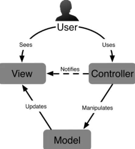
Several architectural models have been introduced to structure modules such as the GUI in an interactive application. Among them, the model-view-controller (MVC) has wide acceptance in the development of GUIs. One reason is that it is one of the first serious attempts to structure UIs, dating back to the late 1970’s. In December 1979 at the Xerox Palo Alto Research Laboratory (PARC), Trygve Reenskaug first described the MVC pattern [77].
In this paradigm, Models represent knowledge. They could be a single object or a structure of objects. Views are (visual) representations of their corresponding model. They basically highlight some attributes and suppress others, acting as a “presenta-tion filter”. Finally, Controllers act as the link between a user and the system. The idea behind this pattern is to make a clear distinction between domain objects which model real world elements, and GUI elements depicted on the screen.
The MVC architecture defined by Reenskaug is depicted in Figure 1. There, the Modelmanages the data and behaviour of the application domain. It responds to requests about its current state (usually from the View) or requests instructions to change its state (usually from the Controller). The View simply manages the layout of the information contained in the Model. This might require to query the state of the Model. Finally, the Controller interprets inputs from the user (keyboard, mouse, etc.) and informs the Model/View.
View
Controller
Model
User
Sees Uses Manipulates Updates NotifiesFig. 1: Model-view-controller architecture
In [21], Burbeck presents two variants of the MVC pattern where the role of the model varies: active or passive. In the passive version, the model is exclusively modified by the controller (i.e., it cannot be modified by any other source). As soon as the controller detects a user action, it modifies the model and informs the view
that the model has changed and should be refreshed (Notifies dotted line in Figure 1). In this scenario, the model is unaware of the existence of the view and the controller. In the active version, the state of the model can be changed by an external component. Since only the model can detect that it has been changed, it needs to notify the view that it must be refreshed. The observer pattern [40] is generally used to keep the model independent from the other components. Views subscribe to be informed of the changes in the model.
We rely on an MVC variant – model-view-presenter (MVP) [72] – to propose a generic architecture for configuration interfaces. It separates the responsibilities for the visual display and the event-handling behaviour into two different compo-nents named View and Presenter, respectively. The View detects changes in the GUI and forwards the corresponding events to the Presenter. That component contains the logic to handle those events. Centralizing the behaviour inside a single compo-nent makes it easier to test, and its code can be shared between different views that have the same behaviour. As for the MVC architectural pattern, MVP comes in two versions: passive view and supervising controller. They are depicted in Figure 2. In the passive version, interactions between the View and the Model are handled exclusively by the Presenter. In the other one, the View can directly interact with the Model for simple events, more complex ones still being handled by the Presenter. In Figure 2, dashed lines correspond to interactions specific to the supervising controller version.
Updates
View
Presenter
Model
User
Sees Uses changesSends Modifies Updates
Notifies
Notifies
Fig. 2: Model-view-presenter architecture
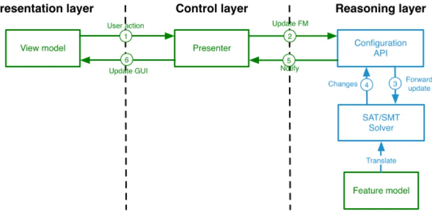
The key idea of our approach is to separate variability reasoning at the FM level, event handling and the actual representation of the GUI. Thus, our architecture is inspired by the passive view version of the MVP pattern and is decomposed into three tiers (see Figure 3).
Here, we focus on the MVP-related models (shown in green in Figure 3) while the supporting components (in blue) are considered as third-party software. The roles involved in our adaptation of the pattern are as follows:
• Model: The model is an FM. The feature model is used to effectively engineer a configuration GUI. It is connected to a reasoning engine which is responsible of interactive configuration and is exposed through a generic API.
• View: The view contains a description of the GUI to be displayed to the user. This description is generated from the FM using transformation rules. Ideally, rather than generating the interface in its implementation language a GUI model should be generated for it. This has two advantages; i) GUI models are more concise and thus easier to generate and ii) we can target several platforms from the same GUI model.
• Presenter: The presenter is the central point of our architecture. It listens to user actions, updates the FM and interacts with the reasoning engine to determine the list of changes to be propagated to the GUI. Once this list is populated, it updates the GUI model by adding, removing, hiding, making visible or updating elements affected by the changes.
User action Update FM Notify Update GUI Forward update Changes Configuration API SAT/SMT Solver Reasoning layer Control layer Presentation layer Presenter View model Feature model Translate 1 2 3 4 5 6
Fig. 3: An MVP architecture for configurators
From a dynamic perspective, interaction between components works according to the numbered arrows. The preliminary step is to translate the FM in a format compatible with the SAT/SMT solver. This translation is made once and allows efficient reasoning by exploiting this robust technology. Once an instance of the FM is encoded within the solver, the configurator can be used interactively. For example, ticking a check box in the GUI will trigger an event through the view model and will be propagated to the presenter ( 1 User action). Depending on the nature of this action, the presenter will generate an update request ( 2 Update FM) for the configuration API. This API will in turn update the FM instance (e.g., by setting a Boolean variable corresponding to the feature associated with the check box to true via 3 Forward update). The solver will compute the new list of features to be (de)selected as a result ( 4 Changes). This result will be transferred to the presenter ( 5 Notify) that will make decisions regarding changes in the GUI. The GUI is then updated ( 6 Update GUI) accordingly.
Our architecture does not use the supervising presenter version of the original MVP pattern in the sense that there is no direct link between the FM and the view
model. The main reason is that interactive configuration can induce complex GUI updates for which a specific behaviour has to be provided. Since most of this be-haviour can be made generic, presenters can be reused amongst different GUIs.
4 From Feature Models to MVP Configurators
4.1 Illustration
In this section, we illustrate the different languages and components of our approach by modelling a configurator for computer network topologies and IPv6 addressing plans. Preparing an IPv6 addressing plan is an important task for network managers who need to deploy IPv6 in their organizations.
One of the core networking aspects found in addressing plans is the practice of dividing a computer network into multiple networks called subnets. The computers that belong to the same subnet have their IP addresses prefixed by a common bit-group and the exchange of traffic between different subnets is supported by routers. The purpose of an addressing plan is to logically divide the network into subnets based on the structure of the organization so that the IPv6 addresses can be ef-fectively managed in groups. This split can greatly simplify the management of networks, especially within large organizations.
Throughout the remainder of this section, we present the different models sup-porting the generation of GUIs for a configurator that can assist practitioners in their preparation of an addressing plan. We also introduce the required computer network concepts for understanding this domain-specific configuration task.
4.2 Variability Modelling
4.2.1 General Principles & Language
As previously mentioned, FMs are the base models of our approach. However, while they are the de-facto standard for representing the variability in the scientific com-munity, our industry partners, discussions at the 2010 variability modelling (Va-MoS) workshop [11] as well as literature reviews [23, 49] suggest that in the indus-trial world, in contrast, FMs appear to be used rarely. In [47], some of the authors of this chapter identified their shortcomings. To overcome those shortcomings, these authors also designed TVL (Textual Variability Language), a text-based FM lan-guage. The idea of using text to represent variability in SPLE is not new [8, 32] but seems to be recently gaining popularity [3, 28]. In terms of expressiveness, TVL subsumes most existing dialects. The main goal of designing TVL was to provide engineers with a human-readable language with a rich syntax to make modelling
easy and models natural. Further goals for TVL were to be lightweight (in contrast to the verbosity of XML for instance) and to be scalable by offering mechanisms for structuring the FM in various ways.
Basically, the TVL language has a C-like syntax: it uses braces to delimit blocks, C-style comments and semicolons to delimit statements. The rationale for this tax choice is that nearly all computing professionals have come across a C-like syn-tax and are thus familiar with this style. Furthermore, many text editors have built-in facilities to handle this type of syntax.
In TVL, the root keyword is used for the root feature and each decomposition is introduced by the group keyword, which is followed by the decomposition type. The and, or, and xor decomposition types were renamed to allOf, someOf and oneOf in TVL. These names are inspired by [32] and make the language more accessible to people not familiar with the Boolean interpretation of decomposition. The decom-position type can also be given by a cardinality. Cardinalities can use constants, nat-ural numbers, or the asterisk character (which denotes the number of children in the group). The decomposition type is followed by a comma-separated list of features, enclosed in braces. If a feature is optional, its name is preceded by the opt keyword. Each feature of the list can declare its own children. If each feature lists its children this way, the tree structure of the FM will be reproduced in TVL with nested braces and indentation. This can become a scalability problem for deep models, something we experienced in industrial cases. To this end, TVL allows one to declare a feature in the decomposition of its parent by just providing a name. A declared feature can then be extended later on in the code. Besides the group block, a feature can contain constraint and attribute declarations, all enclosed by a pair of braces. If there is only a group block, braces can be omitted. This reduces the number of braces in a pure decomposition hierarchy. To model a Directed Acyclic Graph (DAG) structure (as in FORM [54]), a feature name can be preceded by the shared keyword, meaning that it is just a reference to a feature already declared elsewhere.
Attributes can be defined inside the body of a feature. They are declared like variables in C, in order to be intuitive for engineers. The attribute types supported by TVL are integer (int), real (real), Boolean (bool), and enumeration (enum) whose values set is specified with the in keyword. TVL further provides syntactic sugar to define the domain and the value of an attribute. If the value of an attribute depends on whether its parent feature is selected or not, the ifIn: and ifOut: keywords can be used. Furthermore, to concisely specify cases in which the value of an attribute is an aggregate of another attribute that is declared for each child, an aggregation func-tion can be used in combinafunc-tion with the children and selectedChildren keywords (followed by an ID denoting the attribute).
In TVL, constraints are Boolean expressions inside the body of a feature. There is also syntactic sugar for guarded constraints. Constraints can be guarded using the same ifIn: and ifOut: guards as for attributes.The ifIn: guard means that the constraint only applies if the parent feature is selected. To facilitate specifying con-straints and attribute values, TVL comes with a rich expression syntax. The syntax is meant to be as complete as possible in terms of operators, to encourage writ-ing of intuitive constraints. For instance, to restrict the allowed values of an enum,
the set-style in operator can be used. For enum e in {a, b, c, d, ..}, the constraint e in {b, c} serves as syntactic sugar for e != a && e != d && .., which is much less readable.
TVLoffers two mechanisms that can help engineers structure large models. The first is the include statement, which takes as parameter a file path. As expected, an include statement will include the contents of the referenced file at this point. Includes are in fact preprocessing directives and do not have any meaning beyond the fact that they are replaced by the referenced file. Modellers can thus structure the FM according to their preferences. The second structuring mechanism, hinted at before, is that features can be defined in one place and be extended later in the code. Basically, a feature block may be repeated which adds constraints and attributes to the feature. These mechanisms allow modellers to organise the FM according to their preferences and can be used to implement separation of concerns [83]. This way the engineer can specify the structure of the FM upfront, without detailing the features. Feature attributes and constraints can be specified in the second part of the file, or in other files using the include statement. The only restriction is that the hierarchy of a feature can only be defined at one place (i.e., the group keyword can only be used once for each feature).
More detailed information about TVL can be found in [20, 24].
TVL2
Hereabove, we introduced TVL as we initially defined it [20, 24]. In the meantime, the language has been extended by other researchers in our laboratory. The purpose of those extensions is to support all constructs found in industrial cases. Basically, three main constructs were added, string attributes, feature cardinalities and feature references.
A string attribute is defined using the string keyword. Similarly to other attribute types, an ID is then given to the attribute. The naming convention is the same, the at-tribute ID has to start with a lower case letter. For example, “string myString” is a valid attribute declaration. It is also possible to define string constants in TVL2.
In the original TVL syntax, each feature can be configured (at most) once. Like most existing languages, ours lacks a construct that allows to duplicate a sub-tree of the FM to configure a product. TVL2now supports so-called feature cardinalities.
Their semantics is defined elsewhere [62] and will not be addressed here. Syntac-tically, feature cardinalities are represented in a similar way to group cardinalities, with bounds between brackets. The cardinality directly follows the name of a fea-ture. If it is not defined, the [1..1] cardinality is assumed. Furthermore, the root feature cannot have a cardinality, i.e., it still has to be unique. Bounds can be either an integer value or a constant, or the asterisk character. Here, the asterisk character means that the number of feature instances is unlimited.
A feature reference is an attribute which value identifies an instance of a multi-feature. It is declared by using the keyword shared and the type of the targeted multi-feature. For example, “shared F myFeatureRef” represents a feature
reference which name is myFeatureRef and which type is F. If we assume that the cardinality of F is [0..2], then the value of myFeatureRef can be either F-0 or F-1 which represent the two potential instances of F.
4.2.2 Addressing Plan Example
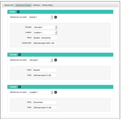
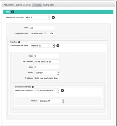
We present a TVL model for the configuration of subnets and the allocation of IPv6 addresses. The model is visible in Listing 1. There, constraints have been removed in order to keep the code as compact as possible. The root feature is decomposed into four sub-features. The feature named Subnet (lines 18-23) contains information related to a subnet such as its name or its IPv6 prefix. It also contains two feature references that targets the sibling features UseType (lines 24-27) and Location (lines 28-31). These two features represent the groups that are defined within an addressing plan and that determine how IPv6 address blocks will be distributed in the organization. For example, in the case of a university campus, the groups could be defined by a set of use types such as student, staff or professors which refer to the different types of users on the network, and by a set of locations such as computer sciencesor economics which refer to the different faculty buildings on the campus. By identifying each subnet by a pair of use-type and location, the ad-dressing plan guarantees that the IPv6 addresses will be consistently distributed. For example, it can ensure that all students in economics will be assigned an IP address from the same subnet. Below the root feature, there are six attributes (lines 6-15). The attribute spacePrefix represents the IPv6 prefix of the network. The at-tribute groupingStrategy indicates whether subnets are primarily identified by use types or by locations. useTypes indicates the total number of use types for the addressing plan and futureUseTypes represents the number of new use types that could emerge in the future. Likewise, locations indicates the total number of locations and futureLocations indicates the number of potential future locations. The feature Host (lines 32-56) contains information related to hosts on the network. The attribute subnet represents the subnet which the host belongs to. The feature Interface (lines 36-48) represents the communication interfaces through which the host sends packets to other hosts on the network. The feature ConnectedInterface (lines 44-46) represents the interfaces that be-long to neighbor hosts and which the host can directly send packets to. Finally, the feature RoutingTableEntry (lines 49-54) represents lines in the routing table of the host. The attribute destination represents the addresse(s) that must be eventually reached by the sent packets. The attribute sendingInterface rep-resents the local interface from which the host sends packets, while the attribute nextHoprepresents the neighbor interface which the host must forward the pack-ets to.
Listing 1: TVL model (excl. constraints) for the IPv6 addressing plan configurator
1 enum G r o u p i n g S t r a t e g y i n { L o c a t i o n F i r s t , U s e T y p e F i r s t } ; 2
4 5 / / A d d r e s s s p a c e 6 s t r i n g n e t w o r k P r e f i x ; 7 G r o u p i n g S t r a t e g y s t r a t e g y ; 8 9 / / Use t y p e s 10 i n t u s e T y p e s ; 11 i n t f u t u r e U s e T y p e s ; 12 13 / / L o c a t i o n s 14 i n t l o c a t i o n s ; 15 i n t f u t u r e L o c a t i o n s ; 16 17 group someof { 18 S u b n e t [ 0 . . ∗ ] { 19 s h a r e d UseType u s e T y p e ; 20 s h a r e d L o c a t i o n l o c a t i o n ; 21 s t r i n g s u b n e t N a m e ; 22 s t r i n g s u b n e t P r e f i x ; 23 } , 24 UseType [ 0 . . ∗ ] { 25 s t r i n g useTypeName ; 26 s t r i n g u s e T y p e P r e f i x ; 27 } , 28 L o c a t i o n [ 0 . . ∗ ] { 29 s t r i n g l o c a t i o n N a m e ; 30 s t r i n g l o c a t i o n P r e f i x ; 31 } , 32 H o s t [ 0 . . ∗ ] { 33 s t r i n g hostName ; 34 s t r i n g l o o p b a c k ; 35 group someof { 36 I n t e r f a c e [ 0 . . ∗ ] { 37 s t r i n g i n d e x ; 38 s t r i n g m a c A d d r e s s ; 39 r e a l d e l a y ; 40 s h a r e d S u b n e t s u b n e t ; 41 s t r i n g i p A d d r e s s ; 42 43 group a l l o f { 44 C o n n e c t e d I n t e r f a c e [ 0 . . ∗ ] { 45 s h a r e d I n t e r f a c e c o n n e c t e d I n t e r f a c e ; 46 } 47 } 48 } , 49 R o u t i n g T a b l e E n t r y [ 0 . . ∗ ] { 50 s t r i n g d e s t i n a t i o n ; 51 i n t m e t r i c ; 52 s h a r e d I n t e r f a c e s e n d i n g I n t e r f a c e ; 53 s h a r e d I n t e r f a c e n e x t H o p ; 54 } 55 } 56 } 57 }
58 }
4.2.3 Widget Selection
When thinking about GUI generation, the first task that comes to mind is to trans-late the different FM constructs into graphical widgets. In other words, the question is: how should the different TVL constructs be rendered in a configurator? For this purpose, we have analysed some existing software configurators [2]. More specifi-cally, 111 Web-based configurators were investigated since they represent a signifi-cant share of existing GUIs today. The (less formal) analysis of configuration GUIs implemented in other technologies has confirmed most findings. “How are config-uration options visually represented and what are their semantics?” is the research question which helped us to identify the types of widgets, their frequency of use, and their semantics (i.e., the corresponding FM constructs). In decreasing order, the most popular widgets in Web-configurators are: combo box item, image, radio button, check button and text box. Some of them are also combined with images, namely check button, radio button and combo box item. In that case, option selec-tion is performed either choosing the image or using the widget. Other less frequent widgets are slider, label, file picker, date picker, colour picker, etc.
The most significant outcome of this empirical study is that the range of graphical widgets is not very large. Actually, according to our analysis, only five of them seem sufficient to represent most variability constructs. We could thus confine ourselves to those widgets, but this would too drastically limit our approach which aims to be generic. It is therefore necessary to propose a more flexible mapping in order to meet user requirements. Nevertheless, we should also impose some restrictions to ensure the generation of “coherent” GUIs. By coherent, we mean that a widget representing a given variability construct should reflect its semantics. For example, check boxesshould be avoided to represent xor-decompositions to avoid confusion. Note that this could be mitigated by adding a label warning the user that the choices are mutually exclusive.
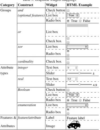
We thus proposed a mapping between FM constructs and GUI widgets. Cus-tomization of the interface is made possible by offering several widgets for most variability constructs. All those mappings are summarized in Table 3. It is di-vided into 3 main categories: Groups, Attribute types, and Features & Attributes. The second column represents the different constructs of each cat-egory. The name of the different widgets associated to each construct are displayed in the third column and illustrated in the HTML format in the last one.
Table 3: Graphical widgets mappings
Category Construct Widget HTML Example Groups and Check button
(optional features)List box Radio box
or List box
Check box xor List box
Radio box cardinality Check box Attribute integer Text box types Slider
real Text box Slider Boolean Check button
List box Radio box enumeration List box
Radio box Features & feature/attribute Label Attributes Image
4.3 View Definition
4.3.1 General Principles & Language
Previously, we presented mappings between FM constructs and GUI widgets. That might be adequate for simple FMs but the limits of such a simple transformation are rapidly reached. First, it does not take the different concerns that might be included in an FM [83] into account. The groups of logically linked constructs vary from person to person and should be taken into account while generating configuration GUIs. Furthermore, the structure of the generated GUI will be strongly related to the FM hierarchy. Indeed, during the generation process, the FM will, in most cases, be traversed using a depth-first approach in order to generate a feature together with its contents, thus resulting in “nested” and “staired” GUIs. Nested since the widgets corresponding to the contents (attributes or group) of a feature will be displayed inside (or under) the widget corresponding to the feature itself. Staired as the width
of the generated GUI will depend on the depth of the FM assuming that an horizontal offset between a feature and its contents exists in the GUI. This offset will be used in most cases in order to depict the relationship between a feature and its contents. The deeper the FM, the wider the generated GUI. While those staired GUIs may be valuable in some cases, they quickly become cumbersome.
To break out of the FM hierarchy, we propose to use views on them. Views are “a simplified version of an FM that has been tailored for a specific stakeholder, role, task, or, to generalize, a particular combination of these elements, which we call a concern. Views facilitate configuration in that they only focus on those parts of the FM that are relevant for a given concern. Using multiple views is thus a way to achieve separation of concerns in FMs”[51].
One of the benefits of views is that they allow to break the hierarchy defined in the FM. However, in some cases this hierarchy is still valuable in the configuration GUI. Consequently, the view definition language should allow to split the FM hierarchy while providing mechanisms to keep the tree structure inherent to such models, at least for sub-parts of it. In the following, some desirable characteristics of such a language are pointed out:
• Full sub-tree – It should be possible to select a sub-tree of the FM. This selection would preserve the structure of the original model. A sub-tree is composed of its root (which can be the FM root or any other feature) and optionally a list of features to exclude (incl. their sub-features and attributes) from the selection, a so-called stop list. The full FM is a specific case where the root of the sub-tree is the FM root and the feature stop list is empty.
• Partial sub-tree – Similarly, it should be possible to select elements in a given sub-tree. This sub-tree would also be defined by a root feature and optionally a stop list. Then, it would be possible to include or exclude some elements like a feature and its contents, an attribute, all groups, all attributes, etc. Here, the structure of the FM is not preserved since the purpose is to select some elements inside a sub-part of it.
• Feature – It should be possible to select a feature and its contents. Mechanisms to select only parts of feature’s contents should also be provided.
• Attribute – Selection of an attribute, and its sub-attributes for structured ones, should also be possible.
We propose TVDL (Textual View Definition Language), a text-based view def-inition language which presents those characteristics for TVL. However, it could easily be applied to any other variability modelling language. As for TVL, the goal of TVDL is to supply engineers with a human-readable and lightweight language.
In TVDL, a view model has to import a TVL FM and is composed of a collection of Views. Basically, a view is given a name and has contents. Its name is a character string starting either with an upper-case or lower-case character. This name must be unique and can thus be used as ID for the view. The contents are then enclosed in braces. Similarly to TVL feature extensions, there is no separator (e.g., semicolon) between the different TVDL views.
We implemented the four different types of views introduced above in TVDL. Additionally, we propose grouping views which are composed of a set of sub-views previously declared. The name of grouping views is preceded by the dollar sign. Each view is composed of one or several view expressions which can be combined using the && symbol. And each view expression reference either a TVL feature or attribute.
The first view expression type, full sub-tree, is defined using the asterisk charac-ter. A so-called stop list can be defined to determine the branches of the FM which are not covered by the view expression. The branch is thus pruned before the stop list element, i.e., it is not included. A stop list is composed of stop elements which are a TVL feature name or its (fully) qualified name preceded by the slash character. A stop list is composed of at least one stop element.
In the partial sub-tree expression, the sub-tree is used as search space. Its pur-pose is to select attributes only, to exclude some features or attributes, to exclude all attributes or groups, etc. contained in a given sub-tree. In this kind of view, the hierarchy is not preserved since one can exclude some elements, so breaking the hierarchy and creating confusion about the semantics of the partial FM. The dif-ference with full sub-tree views is the filter added to the partial sub-tree selection. Three different sub-tree filters exist. They all start with the pipe character. The first one is lists. A list can either be an inclusion or an exclusion (preceded by the excla-mation mark) one. The coverage of an inclusion list is the union of elements covered by each of the list elements. Conversely, the coverage of a sub-tree expression re-fined by an exclusion list is the difference between the set of elements covered by the sub-tree expression and the set of elements covered by the list elements. List elements can be, regardless of the list type, IDs of TVL features or attributes, at-tributesor groups keywords. Those elements can be mixed inside the same list and TVLIDs must refer to constructs covered by the sub-tree expression. If a feature ID is included in an exclusion list, this feature as well as all its contents (attributes and group) will be excluded from the view. Conversely, in an inclusion list, the feature and its contents only will be included in the view coverage. Attribute IDs included in an exclusion (resp. inclusion) list will be excluded (resp. included) in the view coverage, as well as sub-attributes for structured attributes. The groups keyword in an exclusion (resp. inclusion) list will exclude (resp. include) all groups from the view coverage. The same principle applies to the attributes keyword. Attributes are the second kind of refinement for sub-tree expressions. The attributes keyword is used for this purpose. It means that the view covers all attributes contained in the sub-tree expression. It is also possible to further refine the view with a refinement list which can either be an inclusion or exclusion one but, in this case can contain only IDs of TVL attributes covered by the sub-tree expression. This refinement list is also preceded by the pipe character. Finally, it is also possible to select all feature groups contained in a sub-tree of an FM with the groups keyword. In this case, the view coverage is a set of feature groups. It is possible to refine this groups expres-sion with an incluexpres-sion/excluexpres-sion list (preceded by the pipe character). But, in this case, the list contains TVL feature IDs only. We chose to allow features since it is the only way to identify feature groups in TVL. If a feature is covered by an
inclu-sion (resp. excluinclu-sion) list, its group will (resp. will not) be covered by the groups expression.
In TVDL, it is also possible to select a single feature in a view. Similarly to partial sub-trees, refinements exist for those feature selections. The only difference is that the group keyword has to be used instead of groups in the case of partial sub-trees given that each feature contains (maximum) one group in TVL. Finally, refinement lists can also be defined on features. As for partial sub-trees, it can either be an inclusion or exclusion list. This list can contain the TVL ID of the feature’s attributes, and/or the group or attributes keywords. For inclusion lists, the view will cover the feature itself plus the elements mentioned in the list.
The last kind of expression, namely attributes, is the simplest one. Indeed, we have chosen to disallow their refinement. The only way to refine attributes would be to select only some sub-attributes of a TVL structure attribute. But, given our experience in variability modelling, it makes no sense to split such attributes. Indeed, if they had to be split, they would have been represented as a feature with attributes.
4.3.2 Addressing Plan Example
The TVDL model for the addressing plan configurator is given in Listing 2. At line 1, the TVL model previously introduced is imported before defining the four different views. The first one, MainTab (line 3) contains the global properties of the ad-dressing plan that is currently configured. The second view, SubnetTab (line 5), displays information related to subnets and groups in the organization (i.e. use types and locations). The third view, InterfaceTab (line 7), shows information re-lated to the communication interfaces of the hosts that are on the network. Finally, the fourth view RoutingTableTab (line 9) shows the routing table entries of the interfaces. Stop lists are used for defining MainTab, InterfaceTab and RoutingTableTab.
Listing 2: TVDL model for the addressing plan example
1 i m p o r t ” a d d r e s s i n g p l a n d e m o . t v l ” 2
3 MainTab { A d d r e s s P l a n : ∗ / S u b n e t / UseType / L o c a t i o n / H o s t } 4
5 S u b n e t T a b { S u b n e t && UseType && L o c a t i o n } 6
7 I n t e r f a c e T a b { H o s t : ∗ / R o u t i n g T a b l e E n t r y } 8
4.4 Widget Selection
As for FM constructs, we propose a mapping between views and GUI widgets. Each view can be depicted either as a Tab or as a Window. Tabs could be nested in other Tabsor Windows, but not conversely.
4.5 Beautification
4.5.1 General Principles & Language
In the previous sections, our focus was on the direct translation of FM constructs into GUI elements. Even if this translation is technically feasible, the result would be rough as it is relies only on information contained in FMs which is rather technical. For example, using feature and attribute names as label for the input fields might not be expressive enough to understand their meaning.
A first solution would be to extend existing languages. Missing information would be directly added in TVL and TVDL. At the first glance, this solution seems to be the best one in the context of configuration GUI generation. All information would be located in the same place. While this might help to design configuration GUIs, variability and view models would be cluttered with GUI-related informa-tion. This information is completely irrelevant in other contexts and might disturb variability modellers. We want to keep TVL and TVDL languages independent of the GUI generation process in order to preserve the separation of concerns [83]. For all those reasons, we chose to propose a new language dedicated to GUI-specific information.
This language plays the same role as CSS (Cascading Style Sheets) [85] for HTML pages, i.e., it contains beautification information. For this reason, we called our language FCSS, standing for Featured Cascading Style Sheets. As in usual CSS, properties include layout information but also feature-specific visualisation strate-gies. Other properties are related to the rendering of TVL attributes and groups, and TVDL views. The availability of certain options may also depend on the target language.
An FCSS Beautification Model refers to a TVL model and optionally to a TVDL one. Then, it is composed of four different kinds of parts, namely Global Properties, View Properties, Feature Properties and Attribute Properties.
Global properties definition sections start with the dot character and are, like the three other categories, delimited by curly braces. Several global sections can exist. However each global property can only be defined once in the whole model, i.e., it can neither be defined several times in the same global part nor in different global parts.
A property has a name, and a value separated by a colon. It is closed by a semi-colon. Fourteen global properties exist, five are related to feature groups, four to features, another four to attributes, and a single one for views.
Global Properties
A global group property exists for each kind of TVL decomposition. For and-decompositions, it is named andGroup and can take a single value, namely textbox, at the moment. Setting this property might thus be useless. Our intent is to extend the language in the light of experience with Web configurators, requests from cus-tomers, etc. It can be seen as a variation point whose variants still have to be defined. orGroupis a second global group property which can take either listbox or check-boxas value. xorGroup is the third property and its available values are listbox and radiogroup. The last kind of groups, card-decompositions, is represented by the cardGroupproperty and can, at the moment, take a single value, namely checkbox. Finally, the Boolean groupContainer property is used to determine whether groups and their sub-features have to be visually grouped together in the rendered configu-ration GUI. This is typically done with a bordered box.
The first property dedicated to features is simply called feature and determines how they are rendered in the GUI. Available values are text and image. Those val-ues speak for themselves. The optFeature property determines how optional features have to be rendered. Three values exist, checkbox, listbox, and radiogroup. With a check box, the optional feature is selected if (and only if) it is checked. The list-box contains two values, true and false. Similarly the radio group contains two radio buttons labelled with the same Boolean values. Note that, optional features are gen-erally used with and-decompositions. That may help explain why the andGroup property has a single value. unavailableContent is the third feature property. It can take three values, hidden, greyed, or none. This value determines the strategy to ap-ply with the contents of a feature when the latter is not selected. It can either not be visible to the user (hidden), or visible but not editable (greyed), or visible and ed-itable (none). With this last option, the user can select any option at any time. Given the structure of an FM, setting the value of a construct (attribute or feature) will automatically select all its ancestors in the configuration GUI. Finally, a selectFea-tureproperty exists and can take the same values as optFeature, namely checkbox, listbox, or radioGroup. In TVDL, we allow to not cover a group if all its sub-features are covered. As a consequence, the group is not rendered in the configuration GUI. Given that all its sub-features are depicted, we propose to use a selection widget in front of all of them, similarly to optional features. In this way, the user is still able to select group’s sub-features and the group cardinality will be verified by the solver (the presenter in our architecture). The group is scattered all over the configuration GUI but it is still possible to select its sub-features while sticking to its cardinality.
The four attribute properties correspond to the four attribute types available in TVL. Their purpose is to determine the graphical widget of the corresponding type. The intAttribute and realAttribute properties represent integer and real attributes.
They have the same set of values, namely textbox (a box containing the value) or slider. The rendering of Boolean attributes is influenced by the boolAttribute prop-erty. It can take three values, namely checkbox, listbox, or radioGroup. Note that this set of values is the same as optional features given the Boolean type of both constructs. The last attribute type available in TVL is enumeration. Its correspond-ing global property is named enumAttribute and can take listbox or radiogroup as values.
Finally, it is also possible to influence the rendering of views defined in the TVDL model with the view property. As introduced in previous section, available values are taband window. The tab value means that all views will be represented by tabs in the same window. With the other value, window, each view will be rendered in its own window. In the latter case, navigation links between windows should be made available in each window.
Properties defined inside this global part can be seen as “default” values which can be overridden by other ones defined at a lower (i.e., more specific) level. As a case in point, properties defined at the view level have priority over global ones. Conversely, if a global property is not refined for a given construct, it will be used as default behaviour to generate the corresponding widget in the configuration GUI.
View Properties
View-specific definition sections start with the dollar sign followed by the TVDL ID of the corresponding view. The different properties can then be defined inside the block delimited by curly braces. As for global properties, view-specific ones end with a semicolon.We can classify view-specific properties into two categories: those which apply to the view itself and those which apply to elements covered by the view.
We propose four properties which directly relate to the view referenced in the view-specific definition section (i.e., the TVDL view ID directly following the dollar sign). Using the Boolean generate property, one can define whether or not a view has to be rendered in the configuration GUI. This might, for example, be useful if the user has defined a view which is relevant in some contexts (technical, commer-cial, etc.) but should not be displayed in the GUI. It means that the TVDL model can contain views which are irrelevant for GUI generation. We also propose to define labels and help texts for views. Those properties are named label and help, respec-tively. They both take a double quoted string as value. The label property makes it possible to not use the view ID which might be too technical for the end-user. The help text might help the user understand the meaning or the purpose of a view. It is designer’s responsibility to choose the right words to help configuration GUI users in their task. Finally, we propose the unavailable property which determines what to do with the view contents when the view is not available. Values for this property are hidden, greyed and none, and their meaning is the same as for the unavailable-Contentglobal property.
The other category of view-specific properties is similar to the global properties. Indeed, properties falling in this category will influence the rendering of constructs covered by the view. For this reason, the proposed properties are exactly the same as global ones presented earlier. The fourteen properties will not be recalled here for the sake of conciseness. However, we would like to draw the attention to one of them, view. As a reminder, this property allows to define the widget corresponding to views. Setting this property will have an influence on the views contained in the view corresponding to the view-specific definition section, not on that view itself. The viewproperty thus only makes sense for grouping views. In our opinion, all views declared at the same level should be depicted by the same widget. This explains why we did not propose a widget property in the first category. However, if needed, this property could be easily added.
Feature Properties
The goal of this third category is to set properties for a given feature. Contrarily to the two previous categories, this one covers a single element which is a TVL feature. A feature-specific definition section starts with the ID of a feature in the referenced TVL model. It is the single category which has no starting symbol (like the dot character for global parts, or the dollar sign for views). Its contents are then delimited by curly braces. Seven different feature-specific properties are available.
Among the seven feature-specific properties, three are shared with view-specific ones, namely label, help, and unavailable. Available values and semantics are simi-lar. For this reason, they will not be detailed here.
Four properties that are really specific to TVL features are given. widget is the first one and allows to set the widget for the feature in the rendered configuration GUI. It is the feature-specific counter-part of the feature global and view-specific properties. The same two values are available at the moment, text and images. Sim-ilarly, the opt feature-specific property has the same role as optFeature discussed earlier. As a reminder, available values are checkbox, listbox, and radiogroup. The role of this property is to determine the widget depicting the optionality of the fea-ture in the GUI. This property only makes sense for optional feafea-tures. The select property is equivalent to featureSelect and takes the same three values, checkbox, listbox, and radiogroup. Its role is to set the selection widget for features whose group is not covered by TVDL views. It should thus only be defined for features falling in this category.
The last feature-specific property, group, is a little more complex and has a differ-ent syntax. It can contain other properties. In this sense, a parallel can be drawn with TVLstructattributes. Its contents, replacing its value, are delimited by curly braces. There, six properties can be defined. Three of them are the common ones, label, help, and unavailable. Our experience with existing Web configurators and discus-sions with industrial partners showed that, in some cases, it should also be possible to define this information for groups. The widget property defines the widget for the group. Available values are textbox, listbox, checkbox, and radiogroup. They will
de-pend on the decomposition type, textbox only for and-decompositions, listbox and checkbox for or-decompositions, listbox and radiogroup for xor-decompositions, and checkbox for card-decompositions. The Boolean container property has the same role as the groupContainer global property, that is determine whether the group and its sub-features have to be graphically enclosed together, for example using a box. Finally, the default property defines which group’s sub-feature will be selected in the configuration GUI. Available values will be the group’s sub-features. Ideally, default values should be defined in another language which is out of the scope of this thesis. For this reason, it is temporarily included in FCSS.
Attribute Properties
The last category of properties, attribute-specific ones, is the simplest one. This is due to the nature of attributes which are the simplest TVL constructs. An attribute-specific definition section starts with the # symbol directly followed by the TVL ID of an attribute. The properties are then declared inside a block delimited, like other categories, by curly braces.
The label, help, and unavailable properties are the same as the ones previously discussed. A single property really specific to TVL attributes exists. It is called wid-getand can take textbox, listbox, checkbox, radiogroup, and slider as value. As for group widgets, values will depend on the attribute type. textbox and slider for int and real TVL attributes, checkbox, radiogroup, and listbox for bool attributes, and listboxand radiogroup for enumerations.
4.5.2 Addressing Plan Example
In our addressing plan example, the FCSS model contains only labels for views (e.g. line 6), features (e.g. line 46) and attributes (e.g. line 49). Due to space constraints, only the beginning of the FCSS model is visible in Listing 3. All other entries are similar to those depicted in the code excerpt.
Listing 3: FCSS model for the addressing plan example
1 i m p o r t ” a d d r e s s i n g p l a n d e m o . t v l ” 2 i m p o r t ” a d d r e s s i n g p l a n d e m o . t v d l ” 3 4 / / Views 5 6 $MainTab { 7 l a b e l : ” main ” ; 8 } 9 10 $ S u b n e t T a b { 11 l a b e l : ” S u b n e t s and G r o u p s ” ; 12 } 13
14 $ I n t e r f a c e T a b { 15 l a b e l : ” I n t e r f a c e s ” ; 16 } 17 18 $ R o u t i n g T a b l e T a b { 19 l a b e l : ” R o u t i n g T a b l e s ” ; 20 } 21 22 / / F e a t u r e s and a t t r i b u t e s 23 24 A d d r e s s P l a n { 25 l a b e l : ” A d d r e s s p l a n p r o p e r t i e s ” ; 26 } 27 # A d d r e s s P l a n . n e t w o r k P r e f i x { 28 l a b e l : ” Numero c l i e n t ” ; 29 } 30 # A d d r e s s P l a n . s t r a t e g y { 31 l a b e l : ” S t r a t e g y ” ; 32 } 33 # A d d r e s s P l a n . u s e T y p e s { 34 l a b e l : ” Number o f u s e t y p e s ” ; 35 } 36 # A d d r e s s P l a n . f u t u r e U s e T p e s { 37 l a b e l : ” Number o f f u t u r e u s e t y p e s f o r e x p a n s i o n ” ; 38 } 39 # A d d r e s s P l a n . l o c a t i o n s { 40 l a b e l : ” Number o f l o c a t i o n s ” ; 41 } 42 # A d d r e s s P l a n . f u t u r e L o c a t i o n s { 43 l a b e l : ” Number o f f u t u r e l o c a t i o n s f o r e x p a n s i o n ” ; 44 } 45 46 S u b n e t { 47 l a b e l : ” S u b n e t ” ; 48 } 49 # S u b n e t . u s e T y p e { 50 l a b e l : ” Use t y p e ” ; 51 } 52 # S u b n e t . l o c a t i o n { 53 l a b e l : ” L o c a t i o n ” ; 54 } 55 # S u b n e t . s u b n e t N a m e { 56 l a b e l : ”Name ” ; 57 } 58 # S u b n e t . s u b n e t P r e f i x { 59 l a b e l : ” P r e f i x ” ; 60 }