HAL Id: tel-02965330
https://tel.archives-ouvertes.fr/tel-02965330
Submitted on 13 Oct 2020HAL is a multi-disciplinary open access
archive for the deposit and dissemination of sci-entific research documents, whether they are pub-lished or not. The documents may come from teaching and research institutions in France or abroad, or from public or private research centers.
L’archive ouverte pluridisciplinaire HAL, est destinée au dépôt et à la diffusion de documents scientifiques de niveau recherche, publiés ou non, émanant des établissements d’enseignement et de recherche français ou étrangers, des laboratoires publics ou privés.
applications embarquées
Jianwen Meng
To cite this version:
Jianwen Meng. Diagnostic de la batterie et gestion de l’énergie pour applications embarquées. Energie électrique. Université Paris-Saclay, 2020. Français. �NNT : 2020UPAST003�. �tel-02965330�
Battery fault diagnosis and energy
management for embedded
applications
Thèse de doctorat de l'université Paris-Saclay
École doctorale n° 575, Electrical, Optical, Bio: Physics and Engineering (EOBE)
Spécialité de doctorat: Génie électrique
Unité de recherche : Université Paris-Saclay, CentraleSupélec, CNRS, Laboratoire de Génie Electrique et Electronique de Paris, 91192, Gif-sur-Yvette, France. Référent : Faculté des sciences d’Orsay
Thèse présentée et soutenue à Saint-Quentin-en-Yvelines,
le 01/09/2020, par
Jianwen MENG
Composition du Jury
Emmanuel GODOYProfesseur, CentraleSupélec, Université Paris-Saclay Président François AUGER
Professeur, Université de Nantes
Rapporteur & Examinateur Hamid GUALOUS
Professeur, Université de Normandie Rapporteur &Examinateur Tarek RAISSI
Professeur, Conservatoire National des Arts et Métiers Examinateur Moussa BOUKHNIFER
Maître de Conférences, HDR, Université de Lorraine Directeur de thèse Demba DIALLO
Professeur, Université Paris-Saclay
Co-encadrant & Examinateur Harry Ramenah
G
First of all, I would like to express my sincere gratitude to my PhD supervisors, Prof. Demba DIALLO and Dr. Moussa BOUKHNIFER, for their instructive advice and useful suggestions on my thesis. They give me an independent working environ-ment during this three-year doctoral study, and because of their continuous support, I have been very interested in this research topic.
Secondly, I would also like to express my gratitude to the members of my jury, Prof. Fran¸cois AUGER, Prof. Hamid GUALOUS, Prof. Emmanuel GODOY, Prof. Tarek RAISSI and Dr. Harry RAMENAH, for their presence for my PhD defense and their constructive comments on my work. I appreciate our fruitful discussion very much.
Besides, special thanks should go to my friends and colleagues in ESTACA, es-pecially M. Antoine DURAND, M. Adriano CESCHIA and M. Abdelmoudjib BEN-TERKI. We have spent three years together, this journey was interesting because of you. In addition, I also would like to thank those who have helped me during this journey. I am extremely grateful to them.
Last but not least, I should express my gratitude to my family, especially my parents and my grandparents on my mother’s side. Their support and love make me courageous.
General introduction 6 List of tables 10 List of figures 11 List of abbreviations 14 1 Research background 17 1.1 Introduction . . . 17
1.1.1 Energy storage system . . . 18
1.1.1.1 Capacitor/Supercapacitor . . . 20
1.1.1.2 Superconducting magnetic energy storage . . . 21
1.1.1.3 Flywheel energy storage . . . 22
1.1.1.4 Pumped hydro storage . . . 23
1.1.1.5 Compressed air energy storage (CAES) . . . 24
1.1.1.6 Battery . . . 25
1.1.1.7 Fuel cell . . . 27
1.1.1.8 Summary . . . 28
1.1.2 Hybrid energy storage system . . . 30
1.1.3 Hybridization architecture . . . 32
1.1.4 Energy management strategy . . . 34
1.1.5 Summary . . . 37
1.2 Lithium-ion battery basics . . . 37
1.2.1 Glossary and technical terms . . . 38
1.2.2 Inevitable aging process . . . 43
1.2.3 Unforeseeable abuse conditions . . . 44
1.2.4 Summary . . . 46
1.3 Battery management system . . . 46
1.4 Fault detection and diagnosis . . . 50
1.5 Problem statement . . . 53
1.5.1 Example of FC/battery traction system . . . 53
1.5.1.1 Healthy case . . . 54
1.5.1.2 Aging case . . . 56
1.5.1.3 Soft short circuit case . . . 58
1.6 Conclusion . . . 61
2 Battery state and parameter estimation 62
2.1 Introduction . . . 62
2.1.1 Battery SOC estimation . . . 62
2.1.2 Battery parameter estimation . . . 65
2.1.3 Kalman filtering . . . 66
2.1.3.1 Linear Kalman Filter . . . 66
2.1.3.2 Extended Kalman Filter . . . 67
2.1.3.3 Unscented Kalman filter . . . 68
2.1.4 Summary . . . 70
2.2 Battery modelling . . . 71
2.2.1 Overview of battery model . . . 71
2.2.2 Dynamic equations of battery ECM . . . 74
2.2.3 Dynamic equations of extended battery ECM . . . 75
2.3 Observability analysis . . . 77
2.3.1 Battery ECM decomposition . . . 77
2.3.2 Observability analysis for the extended sub-models . . . 79
2.4 New structure for battery state and parameter estimation . . . 81
2.4.1 Battery model discretisation . . . 81
2.4.2 Battery actual capacity estimation . . . 85
2.4.3 Battery OCV estimation . . . 85
2.4.3.1 Auto regressive exogenous model for OCV estimation 86 2.4.3.2 Extended battery ECM for OCV estimation . . . 87
2.4.4 Battery SOC and ECM parameter estimation . . . 88
2.5 Numerical verification . . . 89
2.5.1 Observability conditions’ assessment . . . 89
2.5.2 Evaluation of the new estimation structure . . . 92
2.6 Conclusion . . . 102
3 Battery incipient short circuit diagnosis 103 3.1 Introduction . . . 103
3.2 ECM with short circuit resistance . . . 105
3.2.1 Model description . . . 105
3.2.2 Battery modeling . . . 106
3.3 Robust state and fault estimator design . . . 106
3.3.1 Linear OCV-SOC case . . . 106
3.3.2 Nonlinear OCV-SOC case . . . 109
3.3.2.1 Fuzzification of OCV-SOC curve . . . 109
3.3.2.2 Fuzzification of robust observers . . . 112
3.4 Numerical verification . . . 113
3.4.1 Short circuit effect . . . 115
3.4.2 Short circuit current estimation . . . 116
3.5.1 Statistical analysis . . . 124
3.5.2 Cumulative Sum fault detection . . . 124
3.5.3 Threshold setting . . . 129
3.5.3.1 Threshold 1 . . . 129
3.5.3.2 Threshold 2 . . . 129
3.5.4 Robustness of the fault detection . . . 129
3.6 Conclusion . . . 130
General conclusion and perspectives 132
R´esum´e en fran¸cais 135
Annex 145
The energy crisis and environmental issues bring the greatest challenge for automobile industry and urge the necessity to develop alternative fuel-driven vehicles [1]. Hence, electric vehicles (EVs), including battery-driven EVs (BEVs), hybrid electric vehicles (HEVs) and plug-in HEVs(PHEVs), gain the ever booming development in recent years [2].
In view of their high energy/power density and extended life cycle, lithium-ion batteries (LIBs) are currently the state-of-the-art power sources for electrified pow-ertrain systems [3]. Doubtlessly, the safety operation of LIBs is of vital importance for the development of EVs. However, LIBs have some potential safety issues that threat the reliable vehicle operation, and accidents happen occasionally due to battery faults.
As a typical type of electrochemical power source, LIBs undergo degradation in both energy capacity and internal resistance during their irreversible aging process [4]. Besides, according to the existing literature, overcharge, overdischarge, internal short circuit and external short circuit are four common electrical abuse conditions that may lead to battery thermal runaway [5–7]. And thermal runaway is a catastrophic failure of on-board batteries [8]. Although researchers have never ceased to explore the mechanisms of thermal runaway, deep insight is still premature [9–11].
From the perspective of automation, the reliable, efficient, and safe operation of on-board lithium-ion batteries requires monitoring, control and management. Moni-toring refers to a continuous determination of battery states during operation. Con-trol maintains the battery states within the safety ranges. Management, generalized from energy management and health management, means a health-conscious energy distribution strategy that decides the battery power flow. Instead of being indepen-dent from each other,these three parts are closely correlated. Among others, battery monitoring plays a primary role, because its output triggers the operating conditions.
Objective of this thesis
Since the aforementioned irreversible aging process and four common electrical abuse conditions can cause serious security problems for the embedded application, fault diagnosis around LIB is the main topic of this thesis. Although various research efforts have been invested for the LIBs because of their wide application, battery fault diagnosis remains challenging and problematic. The main reason is that the battery critical indicators, such as state of charge, state of health, cannot be measured directly. However, the energy management strategy, battery energy control and even battery useful life prediction are closely related to these unmeasurable indicators. Hence, battery fault diagnosis, namely the battery on-line monitoring, is of great importance for the follow-up works.
literature, including the experimentally validated battery model and published ex-perimental information [12–14], we would like to make some new contributions for the battery state and parameter estimation and battery incipient short circuit fault diagnosis. The obtained results can become important supports for future work such as battery fault detection, fault tolerant control and the design of a health conscious energy management/battery charging strategy.
Outline of this thesis
This thesis is mainly structured in 3 chapters: - Chapter 1: Research background
The research background starts with a general review of different energy storage technologies, where proprieties of different energy storage systems are pointed out. Furthermore, considering the limitation of single energy storage technol-ogy for the EV application, hybrid energy storage system and its hybridization architecture are introduced. Besides, energy management strategy, as the high level supervisory control of hybrid energy storage systems, is also discussed. Moreover, as the main studied system in this thesis, the basics of LIB including its inevitable aging process and unforeseeable abuse conditions are presented in detail. Finally, this chapter ends with a real hybrid EV simulation example whose the main aim is to show the importance of battery state estimation and battery fault diagnosis.
- Chapter 2: Battery state and parameter estimation
This chapter is dedicated to the battery aging monitoring based on the equiv-alent circuit model. In fact, the so-called battery monitoring process can be eventually converted to a classical state and parameter estimation problem. A usual method for estimating slowly varying unmeasureable parameters is to in-clude them as the state variables with zero-time derivative condition. We can obtain the extended battery model. Hence, after deducing the necessary ob-servability conditions for the nonlinear extended battery model, a new battery monitoring framework is proposed in this chapter. This extends the traditional battery monitoring frameworks, namely joint and dual estimation methods. The obtained results in this chapter provide an important theoretical support for the battery charge control design and battery on-line monitoring work.
- Chapter 3: Battery incipient short circuit diagnosis
The problem of battery incipient short circuit diagnosis is discussed in this chapter. The slightly modified battery equivalent circuit model provides a new
linear characteristic of the battery OCV (open circuit voltage)-SOC(state of charge) curve, a Takagi-Sugeno fuzzy non-linear observer that specialized for the battery short circuit estimation is proposed. Genetic algorithm has been used for the membership function tuning. In order to complete and improve the battery short circuit diagnosis work, the model-based short circuit estimation is combined with a statistical technique, namely Cumulative Sum, to detect the tiny change of the signal due to the incipient fault. Intensive simulation studies using real experimental data [13–15] have verified the effectiveness of the proposed diagnosis method.
Last but not least, the general conclusion and several perspectives will end this thesis. This PhD work has led to 3 journal papers and 5 international conference papers.
International journal papers:
1. Jianwen MENG, Moussa BOUKHNIFER and Demba DIALLO, Incipient Short Circuit Fault Diagnosis of Lithium-Ion Batteries, Journal of Energy Storage, vol. 31, 101658, 2020.
2. Jianwen MENG, Moussa BOUKHNIFER and Demba DIALLO, Comparative study of lithium-ion battery open-circuit-voltage online estimation methods, IET Electrical Systems in Transportation, vol. 10, pp. 162–169, 2020
3. Jianwen MENG, Moussa BOUKHNIFER, Demba DIALLO and Tianzhen WANG, A New Cascaded Framework for Lithium-Ion Battery State and Parameter Es-timation, Applied Sciences, vol. 10, pp. 1–20, 2020.
International conference papers:
1. Jianwen MENG, Moussa BOUKHNIFER and Demba DIALLO, Lithium-Ion Battery Monitoring and Observability Analysis with Extended Equivalent Cir-cuit Model, 28th IEEE Mediterranean Conference on Control and Automation (MED’2020), Saint-Rapha¨el, France.
2. Jianwen MENG, Moussa BOUKHNIFER, Demba DIALLO and Tianzhen WANG, Short-Circuit Fault Diagnosis and State Estimation for Li-ion Battery using Weighting Function Self-Regulating Observer, 2020 IEEE Prognostics and Sys-tem Health Management Conference (PHM-Besan¸con), Besan¸con, France.
plication, IECON 2019-45th Annual Conference of the IEEE Industrial Elec-tronics Society, Lisbon, Portugal.
4. Jianwen MENG, Moussa BOUKHNIFER and Demba DIALLO, A New Model-Based Lithium-Ion Battery Online Monitoring Structure, 2019 IEEE Prognos-tics and System Health Management Conference (PHM-Paris), Paris, France. Best paper award
5. Jianwen MENG, Moussa BOUKHNIFER and Demba DIALLO, A Comparative Study of Open-Circuit-Voltage Estimation Algorithms for Lithium-Ion Batteries in Battery Management Systems, 2019 6th IEEE International Conference on Control, Decision and Information Technologies, Paris, France.
1.1 Principle characteristics of different battery technologies . . . 27
1.2 Comparison of different FC technologies . . . 29
1.3 High power and high energy ESS technologies classification . . . 31
1.4 Currently proposed hybrid ESS configurations . . . 32
1.5 Current main lithium-ion technologies for electrified powertrain . . . . 39
2.1 Resume of ECM-based battery SOC estimation . . . 64
2.2 Characteristics of the added noises . . . 95
2.3 Computation efficiency of the new proposed monitoring structure. . . 102
3.1 Electrical characteristics of SAMSUNG ICR 18650-22P cell . . . 113
3.2 SAMSUNG ICR 18650-22P LIB cell parameters . . . 114
3.3 Linear robust SOC observer design and MF optimization results . . . 116
3.4 SNR of the estimated Isc in Fig. 3.15. . . 123
1.1 Global annual emissions of fossil CO2 from 1970 until 2018 [16]. . . 17
1.2 The main functions of ESS. . . 19
1.3 Energy storage technologies classification. . . 20
1.4 Schematic diagram of SC’s symmetric structure [17]. . . 21
1.5 Schematic diagram of SMES [18]. . . 22
1.6 Schematic diagram of FES [19]. . . 23
1.7 Conceptual PHS system with wind turbines [20]. . . 24
1.8 Example of the machine hall of the Huntorf CAES plant [21]. . . 25
1.9 Schematic diagram of FC [1]. . . 28
1.10 Ragone plot with different ESSs. . . 30
1.11 Basic idea of hybrid ESS. . . 31
1.12 Example of hybrid ESS’ interests in reducing weight, cost and fuel consumption (BATT refers to single battery ESS, FC refers to single FC ESS, HYB refers to hybrid ESS of FC/battery) [22]. . . 33
1.13 Hybridization architectures of hybrid ESS. . . 34
1.14 Classification of EMSs [1, 3]. . . 35
1.15 Working principle of a lithium-ion battery cell. (Redrawn with [23]) . 38 1.16 Expected battery technology commercialisation timeline [2]. . . 39
1.17 Schematic diagram of SOC definition for a single battery cell [24]. . . 40
1.18 Example of battery OCV. . . 42
1.19 Degradation mechanisms in LIB cells [25]. . . 43
1.20 Cause and effect of degradation mechanisms and associated degrada-tion modes [25]. . . 44
1.21 Chain reaction-like relationship among mechanical/electrical/thermal abuses. . . 45
1.22 General causal relationship among the common battery electrical abuses 45 1.23 Schema of battery monitoring, control and management. . . 47
1.24 Classification of different faults. . . 50
1.25 Illustration of the difference between fault and failure. . . 50
1.26 Classification of FDD methods. . . 52
1.27 Considered example of FC/battery traction system [26]. . . 53
1.28 One cycle’s speed profile of WLTC2. . . 54
1.29 Vehicle velocity in the healthy case. . . 55
1.30 Power demand and supply in the healthy case. . . 55
1.31 Voltage of FC/battery in the healthy case. . . 56
1.32 SOC of FC/battery in the healthy case.. . . 56
1.33 Vehicle velocity in the aging case. . . 57
1.34 Power demand and supply in the aging case. . . 57
1.35 Voltage of FC/battery in the aging case. . . 58
1.36 SOC of FC/battery in the aging case. . . 58
1.37 Vehicle velocity in the soft short circuit case. . . 59
1.38 Power demand and supply in the soft short circuit case. . . 59
1.39 Voltage of FC/battery in the soft short circuit case. . . 60
1.40 SOC of FC/battery in the soft short circuit case. . . 60
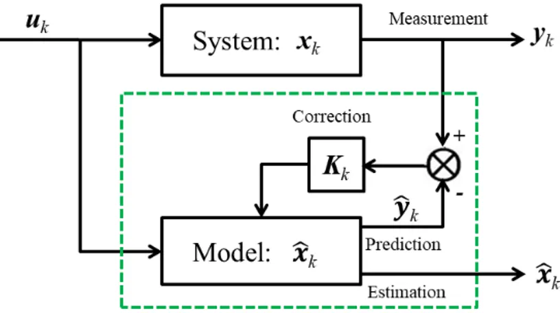
2.1 Schematic diagram of the “Prediction-correction” principle. . . 67
2.2 Schematic diagram of the unscented transformation for mean and co-variance propagation [27] . . . 69
2.3 Battery ECM with double-RC network. . . 74
2.4 General shape of average OCV curve. . . 75
2.5 Schematic diagram of extended model based battery monitoring work 76 2.6 Schematic diagram of the analysis process. . . 78
2.7 Validation of the consistency for the model decomposition. . . 79
2.8 Schematic resume of the observability conditions for extended ECM. . 81
2.9 New proposed structure. . . 84
2.10 Three different input currents for the battery. . . 90
2.11 Verification of the time-varying behavior of Ibatt on the estimation of ECM parameters. . . 91
2.12 Corresponding input currents for the battery. . . 91
2.13 Estimation error of R0. . . 92
2.14 Battery input current level effect on battery capacity estimation. . . . 93
2.15 Initial capacity value effect on battery capacity estimation. . . 94
2.16 Experimental validation results of [28] for battery usable capacity es-timation with the joint/dual eses-timation frameworks. (a),(b) are the capacity estimation result with dual estimation framework; (c),(d) are the capacity estimation result with joint estimation result. Both of these two experimental validations are tested with smaller (1 Ah) and larger (2 Ah) initial values in EKF than the true value of 1.5 Ah. . . . 95
2.17 Estimation result of the battery OCV. . . 96
2.18 Estimation error of the battery OCV. . . 96
2.19 Comparison of estimation results with joint EKF, joint UKF and New structure (Cn). . . 97
2.20 Comparison of estimation results with joint EKF, joint UKF and New structure (R1). . . 98
2.21 Comparison of estimation results with joint EKF, joint UKF and New structure (C1). . . 99
2.22 Comparison of estimation results with joint EKF, joint UKF and New structure (R0). . . 100
2.23 Comparison of estimation results with joint EKF, joint UKF and New structure (SOC). . . 101
3.2 Flowchart for robust observer design. . . 110
3.3 Flowchart of the fuzzification process of battery OCV-SOC curve . . . 110
3.4 Identical MFs for modelling and observer design process. . . 112
3.5 Weight function self-regulating state and fault estimator. . . 113
3.6 Tazzari Zero electric vehicle of university of Lille 1 [14] . . . 114
3.7 EV test cycle and the corresponding adapted EV battery cell current response. . . 115
3.8 Battery electrical responses under different SC conditions. . . 117
3.9 (a) optimized MF for each linear segment; (b) fuzzification result of the OCV-SOC curve. (c) weighting factor for each linear segment; (b) fuzzification error. . . 118
3.10 SOC estimation before and after the fault occurrence. . . 119
3.11 SC current estimation before and after the fault occurrence. . . 120
3.12 SOC estimation with different initial SOC values. . . 121
3.13 SOC estimation result (10 Ω0s SC resistance is introduced at the 500th second). . . 122
3.14 SC current estimation result (10 Ω0s SC resistance is introduced at the 500th second). . . 122
3.15 Isc estimation result under different SC conditions. . . 123
3.16 Statistical features of the estimated Isc with 100 Ω’s SC resistance. . . 125
3.17 Statistical features of the estimated Isc with 50 Ω’s SC resistance. . . . 126
3.18 Flowchart of battery SC detection. . . 127
3.19 CUSUM detection results. . . 128
3.20 PDF of mean value of the estimated Isc (Rsc= 100Ω) . . . 129
3.21 Performance of CUSUM under different disturbance conditions (Rsc= 100Ω) . . . 130
1 Sch´ema de surveillance, contrˆole et gestion de la batterie. . . 136
2 Sch´ema de surveillance de la batterie. . . 138
3 Mod`ele ECM de la batterie. . . 139
4 Les conditions n´ecessaires pour l’estimation d’apr`es le mod`ele ´etendu. 140 5 La nouvelle structure propose´e pour la surveillance de batterie. . . 141
6 Approche syst´ematique pour l’estimation de SC. . . 142
7 Sch´ema sur le diagnostic du SC naissant avec le CUSUM. . . 143
AFC Alkaline fuel cell AH Ampere-Hour
ARX Auto regressive exogenous AWG Additive white Gaussian BEV Battery-driven electric vehicle CO2 Carbon dioxide
CAES Compressed air energy storage CUSUM Cumulative Sum
DMFC Direct methanol fuel cell DOD Depth of discharge ECM Equivalent circuit model EKF Extended Kalman Filter EMS Energy management strategy EOL End-of-lifetime
ESC External short circuit ESS Energy storage system EV Electric vehicle
FC Fuel cell
FDD Fault detection and diagnosis FES Flywheel energy storage
Gt Gigatons (1000 megatons = 109 metric tons) HEV Hybrid electric vehicle
ICE Internal combustion engine ISC Internal short circuit
KF Kalman filter
LIBs Lithium-Ion batteries LMI linear-matrix-inequality LTI Linear time-invariant MCFC Molten carbonate fuel cell NaS Sodium sulfur
Ni–Cd Nickel–cadmium Ni–MH Nickel–metal hydride OC Overcharge
OCV Open circuit voltage OD Overdischarge
PAFC Phosphoric acid fuel cell
PEMFC Polymer electrolyte membrane fuel cell PHEV Plug-in HEV
PHS Pumped hydro storage PRBS Pseudo random binary signal RLS Recursive least-squares SC Supercapacitor
SMES Superconducting magnetic energy storage SNR Signal-to-noise ratio
SOC State of charge SOF State of function SOFC Solid oxide fuel cell SOH State of health SOP State of power
TR Thermal runaway TS Takagi-Sugeno
UKF Unscented Kalman Filter UT Unscented transformation VRB Vanadium redox battery
WLTC2 Class 2 worldwide harmonized light vehicles test procedures ZnBr Zinc bromine
Research background
1.1
Introduction
Conventional energy sources, namely the fossil fuels like coal, oil and nature gas, have played an important role in the modernization and economic development of human society. However, the rapid depletion of fossil fuels and the global warming induced by greenhouse gases become the two main ecological threats for this century. Total global annual emissions of fossil CO2 in gigatons (Gt) by sector from 1970 until 2018 are shown in Fig. 1.1. Since the beginning of the 21st century, global CO2 emissions have grown in comparison to the three previous decades.
Figure 1.1: Global annual emissions of fossil CO2 from 1970 until 2018 [16].
Nowadays, due to the enhancement of public environmental protection conscious-ness and the desire for CO2-emission free power generation, more sustainable, eco-friendly, renewable-based energy sources are exploited. These energy sources, also named as distributed (renewable) energy sources, include solar, wind, ocean wave,
tides, etc. And the corresponding electric power generation is termed as distributed generation [29]. Hence, the obtained electrical energy can be utilized, delivered, or stored into another form and converted back to electrical energy when needed.
1.1.1 Energy storage system
Energy storage system (ESS), which refers to an equipment that can perform both functions of storing and releasing energy at an adequate time, safely, efficiently and conveniently, plays a crucial role in the field of renewable energy technologies. Because electrical energy storage is indispensable and required in various applications:
• Renewable power generation
As mentioned previously, researchers resort to renewable energy resources to tackle the climate change that international community is currently facing. However, the intermittent nature of many renewable energy resources, namely their dependency on environmental conditions like wind speed and solar irradi-ance, prevents a continuous power supply to the load. Therefore, their integra-tion into power systems brings inherent variability and uncertainty. The power variation can even degrade the grid voltage stability due to the surplus or short-age of power [30]. Hence, these highly promising power generation technologies are always applied along with an ESS to constitute a hybrid energy system, whose aggregated output can be regulated to match the loads. The function of ESS is to smooth out the fluctuations and improve supply continuity and power quality [31].
• Energy efficient buildings
The building sector is the largest energy consumer in the world [32]. Heating, lighting, ventilation and air conditioning are necessary for large residential or commercial buildings, such as office buildings, apartment buildings, supermar-kets and hospitals. In order to reduce the greenhouse gas emissions in the build-ing sector to a sustainable level, efforts to increase both energy efficiency and the share of renewable energies are required. Hence, reconstruction with better insu-lation and fenestration can doubtlessly reduce the energy losses from buildings. Additionally, application of combined heat and power (micro-cogeneration) sys-tems, namely microgrid framework based on photovoltaic panels, micro-turbine and ESS, can also alleviate the situation by cutting the non-renewable energy demand [33]. The so-called microgrid can be connected to or islanded from the main electric grid. And ESS is an important element for microgrid in both of these two operation modes. In the connected mode, ESS can shave the load peaks, which make the microgrid has less harmful effect on the main electric grid. In the islanded mode, ESS should stabilize the microgrid [34].
The energy crisis, environmental issues and even political concerns bring the greatest challenge for automobile industry and urge the necessity to develop alternative fuel-driven vehicles [1]. Hence, electric vehicles (EVs), including battery-driven EVs (BEVs), hybrid electric vehicles (HEVs) and plug-in HEVs (PHEVs), gain the ever booming development in recent years [2]. All these alter-natives have in common that an internal combustion engine (ICE) is replaced or augmented by electric propulsion, because transportation electrification is seen as an effective way to substantially reduce the overall use of hydrocarbons [35]. ESS is one of the main elements in the powertrain. It should provide the power supply to the propulsion system, which determines both the driving mileage and the dynamic performance. Besides, energy efficiency also benefits from ESS. Considering the actual applications where vehicles operate frequently between static states and dynamic states, the braking energy is considerable during driv-ing process. Instead of dissipatdriv-ing the brakdriv-ing energy in form of heat durdriv-ing driving process, ESS makes the reuse of regenerative energy from vehicle brak-ing become feasible. Namely, durbrak-ing the deceleration process, the kinetic energy is converted into electric energy and stored; inversely, ESS can also send back the stored energy to the power system when the power demand is high such as hill climbing and accelerating. Except for the road transport, ESS is also applied in rail transport [36], maritime transport [37] and air transport [38]. In addition to the three specific examples above, ESS can also be used in uninter-rupted power supply systems [39], aerospace engineering [40], military services [41], ocean engineering lifting system [42], etc. The main functions of ESS can be resumed in Fig. 1.2
Electricity cannot be stored in electrical form in large-scale capacities. On the contrary, it can be easily stored in other forms [18,34]. Fig. 1.3 classifies different ESS technologies based on their primary source of energy, namely storage technologies for electricity can be classified in three categories regarding the type of the stored energy, including electrical, mechanical and chemical [43]. Although the electrical energy can also be stored in the form of thermal energy, it is technically developed but still not widely used [31]. Description of different ESSs in Fig. 1.3 is given briefly as follows.
Figure 1.3: Energy storage technologies classification.
1.1.1.1 Capacitor/Supercapacitor
Conventional capacitors consist of two metal plates separated by a nonconducting layer which is termed as dielectric. When one plate is charged by a direct-current source, the other plate will be induced with charges of the opposite sign. Although capacitors can be charged quickly and cycled tens of thousands of times with a high efficiency, the main problem is the low energy density [18]. If a large capacity is required, the area of the dielectric must be very large, which prevents the application of the conventional capacitors.
Recently, great progress has been achieved in the capacitor storage technologies. Instead of the common arrangement of a solid dielectric between electrodes, an elec-trolyte solution is applied [31]. This is the so-called supercapacitor (SC) , which is also termed as ultracapacitor. A SC cell consists of two electrodes separated by an ion-permeable separator which is soaked in electrolyte [17]. The separator prevents the electrical contact between the electrodes. Fig. 1.4 illustrates the schematic diagram of SC’s symmetric structure.
Depending on the different storage mechanisms or cell configuration, the SCs can be generally divided into three categories, namely electric double-layer capacitors,
Figure 1.4: Schematic diagram of SC’s symmetric structure [17].
pseudocapacitors and hybrid capacitors [17]. The electric double-layer capacitors are non-faradaic (electrostatic) because there are no chemical reactions, while the operation of pseudocapacitors is a faradaic process which involves the transfer of charge between electrodes and electrolyte such as oxidation-reduction reactions [44]. The hybrid capacitors, such as lithium-ion capacitors, are a combination of the two, including both faradaic and electrostatic processes [17, 44].
The SCs possess high specific power typically above 10 kW/kg but low specific energy, typically below 10 Wh/kg, also they are ESSs with very high life cycle typically above 500000 cycles [43]. Although they have greater energy storage capabilities than the conventional capacitors, short duration and high energy dissipation due to self-discharge losses are still the main concerns [44].
1.1.1.2 Superconducting magnetic energy storage
Superconducting magnetic energy storage (SMES) consists of superconductive coil, power conversion system and a cryostat which contains a refrigeration system and a vacuum-insulated vessel [18]. Schematic diagram of SMES is shown in Fig. 1.5. The operation principle of an SMES unit is that when a direct current voltage is applied across the terminals of a superconductive coil, energy will be stored in the magnetic field generated by direct electric current circulating through the superconductive coil [45]. Because of the extreme low resistance of the superconductor, the current in the coil can continue to flow even if the voltage source is interrupted.
SMES is the only known technology to store electrical energy into electric cur-rent [46]. The energy stored in the coil can be calculated by E = 0.5LI2, where L is
Figure 1.5: Schematic diagram of SMES [18].
the coil inductance and I the current [18]. In addition, the coil is maintained at low temperature considering the critical temperature of superconducting phenomenon. Therefore, SMESs are generally categorized in two main types, namely low tempera-ture (around 5 Kelvin degree) and high temperatempera-ture (around 70 Kelvin degree) [34]. Although it exhibits excellent characteristics in high energy storage efficiency (typ-ically >∼ 97% ), high power density and high cycle life, necessity of the refrigeration mechanism is very costly and requires complex maintenance [18]. Besides, the super-conductive coil is very sensitive to temperature changes. Up to now, only a few of them with small capacity are available for commercial use [31].
1.1.1.3 Flywheel energy storage
Flywheel is an ESS that stores the electrical energy in mechanical form. As shown in Fig. 1.6, a typical flywheel energy storage (FES) device consists of four main elements. Namely, a flywheel that spins at a very high velocity to achieve maximum storage of rotational kinetic energy within the given constraints, a containment system that provides a high vacuum environment to minimise windage losses and to protect the rotor assembly from external disturbance, a bearing assembly providing a very low loss support mechanism for the flywheel rotor, and a power conversion and control system for operating the flywheel for energy store or release [18, 19, 47].
During the charging process, the flywheel is accelerated to a very high speed by a motor. The energy is stored in the flywheel by keeping it at a constant speed. During the discharging process, the same motor acts as a generator in order to convert the rotational energy of the flywheel to electrical energy [31]. The total energy of a flywheel system is dependent on the size and speed of the rotor, and the power rating is dependent on the motor-generator [18]. The most utilized electrical machines in flywheel ESS are usually induction machine, doubly fed induction machine or permanent magnet synchronous machine [34].
Flywheel ESS can provide full charge-discharge cycles with little maintenance cost. Besides, high power density and high energy storage efficiency are also the advantages
Figure 1.6: Schematic diagram of FES [19].
of this ESS. But compared with other ESSs, the relatively short duration, high fric-tional loss (high self-discharge loss) and low energy density restrain the flywheel ESS from the energy management application [18, 31, 47].
1.1.1.4 Pumped hydro storage
Pumped hydro storage (PHS) is the most widely implemented large-scale energy storage technology, which is technically mature and has been utilized worldwide for more than 70 years [43]. An example of modern conceptual PHS system with wind turbines is shown in Fig. 1.7.
A typical pumped hydraulic ESS normally consists of two reservoirs located at different elevations, a unit to pump water to the high elevation and a turbine to generate electricity with the water returning to the low elevation [20]. During off-peak hours, it pumps water to a reservoir at a higher altitude than the original one. This can be considered as a charging process, where the produced electrical energy is stored as the potential energy. Then, during peak periods, water from the upper reservoir is released and flows through hydro turbines that are connected to generators. Therefore, electrical energy is produced during this discharging process [20, 31]. To be short, the stored water is transferred between the two reservoirs, when electrical energy is required, the water flows to a lower height reservoir and the potential energy is converted to electrical energy. Clearly, the amount of stored energy is proportional to the height difference between the two reservoirs and the volume of water stored. Moreover, taking into account the evaporation and conversion losses, ∼ 70% to ∼ 85% of the electrical energy used to pump the water into the elevated reservoir can be regained [18].
However, geographical dependence of installation, high cost and environmental concerns (e.g. removing trees and vegetation from the large amounts of land prior to the reservoir being flooded) are the main drawbacks of the pumped hydraulic ESS [18, 43].
Figure 1.7: Conceptual PHS system with wind turbines [20].
1.1.1.5 Compressed air energy storage (CAES)
Except for the pumped hydraulic ESS, compressed air ESS is also a commercially available technology which is capable of providing very large energy storage capacity [18]. The idea of storing electrical energy by means of compressed air dates back to the early 1940s [21]. The world’s first CAES plant was put into operation in 1978 near the northern German village of Huntorf with an output power of 290 MW [21]. An example of the machine hall of the Huntorf CAES plant is shown in Fig. 1.8.
The basic concept of CAES is simple, namely the storage is charged by the use of electrically-driven compressors which convert the electric energy into potential energy [21]. Generally, it consumes off-peak energy to compress air into underground cavities or surface vessel. To extract the stored energy, the compressed air is released and mixed with one of the conventional fuels, burned and expanded to drive a turbine generator to produce electricity [43].
CAES has a relatively long storage period due to very small self-discharge losses, which can be over a year [31]. However, the requirement of fossil fuels, the related contaminating emission, and the reliance on favourable geography render the CAES less attractive [18].
Figure 1.8: Example of the machine hall of the Huntorf CAES plant [21].
1.1.1.6 Battery
Battery, here refers to the rechargeable/secondary battery, is the most widely used ESS worldwide. It stores electricity in the form of chemical energy, and can be designed as high-power or high-energy ESS [48]. Each battery cell is made of a liquid, paste or solid electrolyte together with a positive electrode and a negative electrode [31]. During discharge process, electrochemical reactions occur at the two electrodes which generate a flow of electrons through an external circuit. The reactions are reversible, allowing the battery to be recharged by applying an external voltage across the electrodes [18]. Various types of secondary batteries have been developed for commercial use.
• Lead-acid battery
Lead acid batteries, invented in 1859, are the oldest and most developed battery [18,49]. They are popular storage choice for power quality, uninterruptible power supply and some spinning reserve applications. However, their application for energy management is very limited due to their short life cycle and low energy density [18]. A typical lead-acid battery cell is composed of a sponge metallic lead anode, a lead-dioxide cathode and a sulfuric acid solution electrolyte [49]. It is by far the cheapest energy storage technology with regard to the cost of raw materials [50]. However, the use of heavy metal component is the main concern for this battery type as it makes them toxic and hazardous to the environment [49].
• Nickel battery
Rechargeable nickel batteries are made of active material–nickelous hydroxide as the positive electrode [49]. Although there are various types of nickel based secondary battery, nickel–cadmium (Ni–Cd) battery and nickel–metal hydride (Ni–MH) battery are the most developed [50]. Ni–Cd batteries show a slightly higher energy density and a significantly higher power density than lead–acid batteries. However, Ni–Cd batteries have been banned because of their toxic-ity. Ni–MH batteries are the further development of Ni–Cd batteries, with the aim of creating a battery without toxic cadmium but with the advantages of nickel–cadmium batteries [50]. Even though Ni–Cd battery and Ni–MH battery are widely used in the market, they offer the lowest energy efficiency compared to others [49]. Besides, they also suffer form the memory effect and the strong lifespan dependence on cycle depth [31].
• Sodium sulphur battery
Sodium sulfur (NaS) battery consists of liquid (molten) sulphur at the positive electrode and liquid (molten) sodium at the negative electrode as active mate-rials separated by a solid beta alumina ceramic electrolyte [18]. It is the most developed type of high temperature battery. The battery should be maintained at 300∼350◦C [18, 49]. While NaS batteries not only have outstanding energy and power density, but also they have long life cycle of up to 15 years [18, 49]. These attributes made them attractive for large scale storage devices [49]. How-ever, except for the high cost, the major drawback is that a heat source is re-quired which uses the battery’s own stored energy, partially reducing the battery performance [18].
• Lithium battery
Lithium batteries, composed from lithium metal or lithium compounds at the anode, have the advantages such as light weight, high energy density and high power density [50]. Also the efficiency of lithium battery is almost 100%, which is another important advantage compared to other batteries [18]. The presence of lithium in its ionic rather than metallic state, in principle, overcomes the inherent drawback of lithium-metal cells, namely explosion hazards led by the uneven (dendritic) lithium growth [51]. Thus, various intercalation compounds, mostly studied and applied for the positive electrode, have spawned the diversity of lithium-ion battery family. Because of the increasing interest in EVs, the development of lithium-ion battery has received a significant boost in recent years.
• Metal-air battery
Metal-air battery is the most compact and potentially the cheapest battery available in the market [18, 49]. Instead of an aqueous solution for electrolyte;
the battery uses ionic liquids [49]. Although other metal electrodes have higher theoretical energy density, the most advanced metal-air systems developed to date are the zinc-air and lithium-air batteries [49]. The high energy density and low cost of metal-air batteries make them ideal for many primary battery applications. However, the rechargeable metal-air batteries still need further development, because the current rechargeable metal-air batteries can only op-erate for a few hundred cycles and the efficiency is below 50% [18].
• Flow battery
Furthermore, a promising capacity-oriented energy storage technology is the flow battery. The chemical energy is stored with the electrolyte solutions in two tanks outside the battery cell stacks [49]. Hence, the energy rating is determined by the quantity of electrolyte, while the power rating is dependent on the active area of the cell stack [18]. Compared to conventional batteries, the main advantage of flow battery is that it is possible to design the battery to have optimal power acceptance and delivery properties without needing to maximize the energy density [49]. The typical flow batteries are vanadium redox battery (VRB) and zinc bromine (ZnBr) battery [48]. The main studies on flow battery have focused on stationary applications [18].
Principle characteristics of the different battery technologies, namely energy den-sity, power denden-sity, operating temperature and durability, are listed in table 1.1 [35, 52–54].
Table 1.1: Principle characteristics of different battery technologies
Battery technology Energy density (Wh/kg) Power density (W/kg) Operating temperature Durability (years) Cost ($/kWh) Lead-acid 30∼50 75∼300 -20∼50◦C 10 200∼400 Ni-MH 30∼110 250∼2000 -20∼65◦C 3∼15 800∼1500 Lithium-ion 75∼250 100∼5000 -20∼60◦C 5∼20 600∼2500 NaS 150∼240 150∼230 300∼350◦C 15 300∼500 VRB 10∼75 80∼150 -5∼50◦C 10∼20 150∼1000 ZnBr 60∼85 50∼150 20∼50◦C 5∼20 150∼1000 Zinc-air 110∼3000 ∼100 0∼60◦C - 10∼60 1.1.1.7 Fuel cell
Fuel cell (FC) is an electrochemical energy conversion device that can generate elec-tricity via oxidation-reduction reactions. It is actually a reversed electrolysis reac-tion [55]. The FC efficiently converts the chemical fuel into electrical energy at a
continuous steady rate to provide extremely high energy density [43]. A schematic diagram of FC is shown in Fig. 1.9.
Figure 1.9: Schematic diagram of FC [1].
Although there are different types of FCs, they all operate with the same basic principles. Namely, they produce electricity from external supplies of fuel (anode side) and oxidant (cathode side), and the by-products are water and heat. Generally, a FC consists of four main parts, namely anode, cathode, electrolyte and the external circuit. The reactants flow in and reaction products flow out, while electrolyte remains in the cell [18]. Hydrogen is oxidized into protons and electrons at the anode, while oxygen is reduced to oxide species and reacts to form water at the cathode.
The main difference in various FC designs is the chemical characteristics of the electrolyte. Depending on the electrolyte, either protons or oxide ions are transported through an ion-conductor electron-insulating electrolyte while electrons travel through an external circuit to deliver electrical power [55]. Currently, six major different types of available fuel cells are polymer electrolyte membrane fuel cell (PEMFC), alkaline fuel cell (AFC), phosphoric acid fuel cell (PAFC), molten carbonate fuel cell (MCFC), solid oxide fuel cell (SOFC) and direct methanol fuel cell (DMFC) [56]. Comparison of these different FC technologies is shown in table 1.2.
1.1.1.8 Summary
In summary, ESS technologies have complementary characteristics in terms of power and energy density, life cycle, response rate, etc. The ideal ESS should offer fast access
T able 1.2: Comparison of differen t F C tec hnologies F C typ e Electrolyte Charge carrier F uel Op erating temp erature Cell v oltage Electrical efficiency Application PEMF C Solid p olymer mem brane H + Pure H2 50 ∼ 100 ◦ C 1.1 V 53-58% Bac kup p o w er, p ortable p o w er, small distributed generation, transp ortation AF C Liquid solution OH − Pure H2 50 ∼ 200 ◦ C 1.0 V 60% Military , space P AF C Phosphoric acid H + Pure H2 ∼ 200 ◦ C 1.1 V > 40% Distributed generation MCF C Lithium and p otassium carb onate CO − 2 3 H2 ,CO, CH 4 , other ∼ 650 ◦ C 0.7-1.0 V 45-47% Electric utilit y , large distributed generation SOF C Stabilized solid o xide electrolyte O − 2 H2 ,CO, CH 4 , other 800 ∼ 1000 ◦ C 0.8-1.0 V 35-43% Auxiliary p o w er, electric unit y , large distributed generation DMF C Solid p olymer mem brane H + CH 3 OH 60 ∼ 200 ◦ C 0.2-0.4 V 40% Mobiles, computers and other p ortable devices
to power whenever needed, provides high energy capacity, has a long life expectancy and be available at a competitive cost. However, there is no energy storage technology currently available that can meet all these desirable characteristics simultaneously [48]. Furthermore, power density and energy density are two main characteristics of ESS, which are usually plotted in the same figure in order to compare the performance of different energy storage techniques. The obtained figure, as shown in Fig. 1.10, is the so-called Ragone plot. High power density means that the ESS can supply energy at very high rates, but characteristically for short time periods; alternatively, high energy density means that the ESS can supply energy for longer time periods. Besides, high power ESSs possess fast response rate, while high energy ESSs have slow response rate [43]. Hence, in analogy to data storage in computer engineering, a classification in terms of access and capacity orientation can be considered for ESS [48]. Table 1.3 categorizes ESS technologies based on this classification.
Figure 1.10: Ragone plot with different ESSs.
1.1.2 Hybrid energy storage system
Several ESS applications require a combination of energy and power rating, life cycle, and other specifications that cannot be fulfilled by a single ESS technology [43]. Hence, the idea of hybrid ESS lies on the fact that electronically combining the power output of two or more devices with complementary characteristics can increase the advantages that a single ESS technology can offer without fundamental development of the storage mechanism [43]. After coupling two or more ESS technologies together, namely combining the appropriate features of different technologies, the hybridization
Table 1.3: High power and high energy ESS technologies classification
High power devices (access-oriented)
High energy devices (capacity-oriented)
SC Pumped hydro
SMES CAES
Flywheel FC
High-power battery High-energy battery
can provide excellent characteristics not offered by a single ESS unit [57].
As it is shown in Fig. 1.11, the basic idea of hybrid ESS is to combine high energy devices with high power devices in order to yield a more functional ESS. The high power device should supply short term power needs, while the high energy device should meet long term energy needs. In other words, the access-oriented storage absorbs or delivers the transient and peak power, and the capacity-oriented storage fulfills the slowly varying and steady-state power demand [48]. Hence, based on this idea, the currently proposed hybrid ESS configurations are listed in table 1.4. Note that although a pumped hydro ESS is used as an energy supplier ESS unit, the relevant hybridization has not yet been proposed [43].
Figure 1.11: Basic idea of hybrid ESS.
Except for enhancing the dynamic performance of the energy storage, lifespan im-provement is also a significant benefit of ESS hybridization. Especially in embedded application, where reliability is of vital importance. Embedded applications, such as EV, have strong requirement on reliability, energy efficiency and dynamic perfor-mance. Hence, EV is intended to be powered by a hybridized source. As our main topic is EV, in the following, we will focus on ESS suitable for this application.
Battery, SC and FC are the most studied energy storage devices in the elec-trified vehicle power train [58]. Especially the hybridization based on the PEMFC has received considerable research attention in recent years. Because PEMFC has
Table 1.4: Currently proposed hybrid ESS configurations
Energy supplier Power supplier
Battery SC SMES Flywheel CAES SC Flywheel FC SC SMES Battery
high power density, appropriate operating temperature and low corrosion compared to other types of FCs [3]. Thus, the vehicle all-electric range can be guaranteed by PEMFC. Additionally, one of the main concerns about EV application, namely the long charging time, can also be eliminated by the fast hydrogen filling process. Hence, hybrid ESS based on PEMFC and battery/SC is very promising for the next EV gen-eration [1]. However, the lifetime of current PEMFC vehicle, evaluated only at 3900 hours in 2015, cannot satisfy the commercial use [22]. Because a 5000-hour’s PEMFC lifetime requirement is requested for the light-duty EV market [3]. Owing to this, the advantage of using a hybrid ESS can be highlighted. The presence of battery/SC can meet the instantaneous power demand of the vehicle, which tries to improve the PEMFC power leveling. The less fluctuating power demanded from PEMFC will con-sequently prolong its lifespan. In turn, PEMFC will maintain the energy stored in the battery/SC at an adequate level, which will avoid frequent cyclic charging and dis-charging of battery/SC. Hence, the hybridization can prevent premature degradation of each component [1].
Moreover, reducing the weight, cost and fuel consumption are also relevant ob-jectives for using hybrid ESS in EV application [59]. Results displayed in Fig. 1.12 shows that FC/battery-based hybrid ESS can achieve longer mileage with less weight, cost and fuel consumption compared with the corresponding single ESS system.
1.1.3 Hybridization architecture
Conditioning circuitry is required when combining two or more energy storage devices acting as a single power source. Numerous hybridization architectures have been proposed to achieve this aim ranging from simple to very flexible [35]. The presence of power electronic interfacing circuits brings more flexibility and scalability to the hybrid ESS. Thus, more choices in implementing control and energy management strategies have been proposed [48]. Besides, the complexity and cost of hybrid ESS
(a) Weight reduction (b) Cost reduction
(c) Fuel consumption reduction
Figure 1.12: Example of hybrid ESS’ interests in reducing weight, cost and fuel consumption (BATT refers to single battery ESS, FC refers to single FC ESS, HYB refers to hybrid ESS of FC/battery) [22].
have also increased. Generally, the connection principle between two energy storage devices can be grouped into three categories as shown in Fig. 1.13.
Fig. 1.13(a) shows direct parallel connection of two energy storage devices, which is also named as passive parallel architecture. It simply connects two ESS technologies together without any power electronic interfacing circuit. This kind of hybridization architecture is simple, but the output voltage of the two ESSs should be equal. Fur-thermore, the absence of power converter makes this architecture become the least expensive one. However, the major problem with this topology is that it cannot effec-tively utilize the energy stored in the ESSs, because the current distribution between ESSs is uncontrolled [60]. Namely, the range of power that is used from either en-ergy source is limited by the voltage swing of the other, where individual maximum
Figure 1.13: Hybridization architectures of hybrid ESS.
power point tracking is not possible for each source [35]. Besides, due to the direct connection of the two ESSs, this architecture has no fault tolerant ability. The faults occurring in one ESS will affect the other one, and will eventually induce malfunction at the system level [43].
Fig. 1.13(b) shows a more complex but flexible solution by combining two energy storage devices. A power converter is used to decouple the two power sources. Hence, it provides more flexibility for active energy management. The power converter con-trols the power output of ESS1, allowing its voltage to vary, while ESS2 delivers the remaining power requirement to the load [35]. Usually, the more sensitive ESS is op-erated as ESS1, because the power conditioning can protect it by adapting its power output. Hence, the lifetime of the overall system can be prolonged [43].
Fig. 1.13(c) shows the active parallel architecture. It has the highest level of flexibility, where each ESS unit has its own power converter. The converters are connected to the common output bus. Each power source can be controlled according to its specific voltage and power. Hence, this hybridization architecture not only allows to developing various energy management strategies, but also it makes the implementation of maximum power point tracking for each ESS possible [35]. In addition, this architecture has the highest level of fault tolerant ability, since the failure of one source does not affect the function of the other one [43, 60].
1.1.4 Energy management strategy
Energy management strategy (EMS) plays an important role for hybrid ESS. Because the basic objective of EMS is to meet the load power demand by determining the power reference for each ESS unit. In other words, EMS can be regarded as the high level supervisory control of hybrid ESS. However, a good EMS not only allows the hybrid ESS to delivering the load’s power demand, but it can also increase the durability and reliability of the ESSs, maintain the global efficiency at its high level. Consequently, designing EMS comes with multiple objectives [1]. Generally, as shown in Fig. 1.14, EMSs can be categorized into rule-based and optimization-based strategies. In this
Figure 1.14: Classification of EMSs [1, 3].
sub-section, different types of EMSs will be briefly presented without the details of design and implementation.
• Rule-based EMSs
The rule-based EMSs can be further divided into deterministic and fuzzy rules. They are usually designed based on human intelligence and experience and generally without prior knowledge of the drive cycle [1]. More advanced rule-based health-conscious EMSs are designed to find efficient operation points that mitigate the energy source degradation [3].
Deterministic rule-based strategies are mainly developed through look-up tables (not real-time data) and among which, thermostat (on/off) strategy, frequency split strategy and state machine strategy are mostly used [3]. Thermostat control strategy is a simple deterministic rule, which tries to operate the energy supplier at highest efficiency point to charge the power supplier when its energy is under the lower thresh-old. This EMS leads to frequent on and off (charging and discharging) on the energy storage devices, which results in the reduction of their lifetime [1]. Frequency split strategy divides power demand into low and high frequency components by low-pass
filtering combined with load-leveling. Compared with the thermostat strategy, it can prevent the premature aging of the energy storage devices [61]. State machine strat-egy divides the hybrid ESS into several functional states according to the different energy state levels of power supplier. For every state, the energy supplier has it own power output decided by the load power. With this strategy, the overall efficiency and lifetime of energy storage devices can be improved [62]. To be short, deterministic rule-based strategies are simple and can be easily implemented in practice. Although optimal results are hardly reached, they are regarded as the most practical way to achieve multiple objectives [1].
Fuzzy rule-based EMSs can be considered as an extension of the deterministic rule-based EMSs. The basic idea is to formulate a collection of fuzzy ”if-then” rules from human knowledge and reasoning, which offers a qualitative description of con-trolled system [61]. Contrary to the deterministic rule-based EMSs, fuzzy rule-based EMSs do not rely on precise system model. Hence, they are particularly suitable for nonlinear, uncertain and time varying systems [3]. Moreover, other advantages of fuzzy rule-based EMS are its robustness to measurement noise and component vari-ability as well as its flexibility [61]. Fuzzy rule-based EMSs use fuzzy inference to transfer the deterministic inputs and outputs into linguistic ones. The fuzzy outputs are then defuzzyfied into precise control signals for the system. The ”if-then” rules can be experience-based, which belongs to the conventional fuzzy logic [41]. While the membership functions can also be tuned by intelligent methods such as neural network algorithm, genetic algorithm. This constitutes the so-called adaptive fuzzy logic. The fuzzy inference technique solves the multi-objective problem by adding multiple inputs and designing proper rules [3].
• Optimization-based EMSs
Optimization-based EMSs, which can be further divided into local optimization and global optimization categories, have received more research interests recently because of their ability to reach optimal results [1]. Fuel economy, durability of power sources, energy cost can be included in an objective function, then the optimal results can be calculated after solving the optimization problem.
Global optimization strategies are carried out based on the overall driving cycle information, which cannot be applied in real-time applications unless the driving cycle could be predicted [61]. Dynamical programming, genetic algorithm, particle swarm optimization are widely used to cope with the global optimization problem. Although they cannot be implemented in real-time control, they can be a good benchmark for other EMSs and give insights for the development of simple and implementable strategies [1].
On the contrary, local optimization based strategy replaces the optimization pe-riod of the whole drive cycle for global optimization strategy into the instantaneous sampling time to calculate instantaneous optimal power split scheme among different
power sources. Equivalent consumption minimization strategy, Pontryagin’s mini-mum principle and model predictive control are usual [1, 59]. Especially the model predictive control, which can be regarded as a “look-ahead” strategy, is an attractive solution for multi-objective EMS design problem [63]. Because it can foresee dynamic changes before they happen and efficiently compute step-wise optimal input control to achieve a defined quadratic performance objective [64].
1.1.5 Summary
Hybrid ESS, combining the advantages of single ESS through power electronic inter-facing circuits, can meet both static and dynamic power demand. In the meanwhile, EMS, as the high level supervisory control, is an essential topic for the hybrid ESS. Hence, fruitful research results about EMS have been made in recent years. However, information of the lower level, namely the real-time operating status of the single ESS, is the basis for designing the EMS. The detailed discussion about the monitoring task for the single ESS can not be ignored.
Therefore, in this thesis, the research efforts are focused on the battery monitoring and diagnosis. Because battery, especially the lithium-ion battery, is the most used ESS in EV application. The following sections are dedicated to lithium-ion battery.
1.2
Lithium-ion battery basics
Although the origin of the term “battery” dates back to 1749, the first real battery has been invented half a century later [65]. Since then, attempts to improve battery’s energy density, power density, reliability, etc. have never ceased. Especially, resorting to lithium is suddenly making the news though it has been discovered for almost two centuries [66]. Features such as high energy/power density and extended life cycle, make lithium-ion batteries become currently the state-of-the-art energy stor-age devices [67]. In particular, lithium-ion batteries are widely used for electrified powertrain systems.
A lithium-ion battery cell mainly consists of four components, namely cathode (positive electrode), anode (negative electrode), electrolyte and a separator that pre-vents contact between cathode and anode [51, 68]. From a chemical point of view, lithium-ion batteries operate through reversible (and usually topotactic) insertion of lithium ions in the electrode materials structure while the electrolyte is ideally chemically inert and impregnates both electrodes and separator to enable ionic trans-port [69]. Fig. 1.15 illustrates the working principle of a lithium-ion battery cell. In brief, lithium ions (Li+) flow from the anode (negative electrode) to the cathode (positive electrode) via the electrolyte and separator diaphragm during a discharge process, and in opposite direction during charging process [23, 68].
The current main lithium-ion technologies for electrified powertrain are listed in table 1.5. The choice of electrode materials will determine the potential and
Figure 1.15: Working principle of a lithium-ion battery cell. (Redrawn with [23])
energy density of the cell [70]. As listed in table 1.5, the cathode is a lithium containing compound such as NMC (LiNixMnyCo1−x−yO2), LFP (LiFePO4), NCA (LiNi0.8Co0.15Al0.05O2), LMO (LiMn2O4) and LTO (Li4Ti5O12) [71–73]; while the an-ode is of porous carbon, and the most commercially popular material is graphite [68]. Besides, as shown in Fig. 1.16, lithium-ion is expected to remain the technology of choice for the next decade. Other technology options are expected to become available after 2030 [2].
1.2.1 Glossary and technical terms
There are many important terms associated with lithium-ion battery. Hence, for the sake of having a better understanding on the follow-up discussion, the related glossary and technical terms will be explained firstly.
• Capacity
Battery capacity, usually expressed using ampere-hour (Ah) as unit, corresponds to the amount of charge that can be withdrawn from a battery until cut-off discharge voltage limit is reached when starting from a fully charged state [74].
However, a difference should be done between battery nominal capacity and bat-tery actual capacity. The batbat-tery nominal capacity, usually indicated on the batbat-tery
Table 1.5: Current main lithium-ion technologies for electrified powertrain
Anode\Cathode Cell nominal tension (V) Eneregy density (Wh/kg) Thermal runaway temperature (◦C) Cost ($/kWh) Cycle life Graphite\NMC 3.8∼4.0 150∼220 210 ∼420 1000∼2000 Graphite\LFP 3.2∼3.3 90∼130 270 ∼580 1000∼2000 Graphite\NCA 3.6∼3.65 200∼260 150 ∼350 500 LTO\LMO 2.3∼2.5 50∼85 safest ∼1005 2000∼25,000
itself, is given by the battery manufacturer and measured under certain conditions when it is new. This value is obtained with the specified standard discharge current under specified temperature [75]. Hence, the actual battery capacity varies signif-icantly from the nominal one, since it not only depends strongly on the operating conditions such as temperature, discharging and charging current etc., but also it decays over the battery’s lifetime due to aging processes [76].
• C-rate
C-rate is a measure of battery charge or discharge current rate, which is normal-ized against battery nominal capacity [72]. For instance, for a battery with nominal capacity of 20 Ah, 1 C’s current is equal to 20 A, 2 C’s current is equal to 40 A, 0.5 C’s current is equal to 10 A.
• State of charge
State of charge (SOC) indicates the residual energy inside a battery cell. It is usually expressed by the ratio of the remaining capacity to the nominal capacity of the cell. The remaining capacity is the number of ampere-hours that can be drawn from the cell before it is fully discharged [24]. 100% means the battery is full charged, and 0% means the battery is empty. Fig. 1.17 shows the schematic diagram of SOC definition.
Figure 1.17: Schematic diagram of SOC definition for a single battery cell [24].
Generally, SOC is calculated based on current integration over charging/discharging time. Namely, the battery SOC ∈ [0%, 100%] can be modeled by the classical Coulomb counting method: soc(t) = soc(t0) − η t Z t0 Ibatt(τ ) Cn dτ (1.1)
where, the variable soc is the operator of SOC; η is the Columbic efficiency which is usually approximated to 1 for LIBs [72]; Cn (Ah) is the battery nominal capacity; soc(t) is the required SOC at time point t based on its initial value soc(t0).
• Depth of discharge
Depth of discharge (DOD) is opposite to SOC (DOD=1-SOC). It describes how much a battery has been discharged [75]. For example, SOC of 20% means the DOD is up to 80%.
• Internal resistance
Internal resistance of a battery is defined as the opposition to the current flow within a battery [75]. It includes the resistance of contacts, electrodes, electrolyte as well as the related electrochemical reactions. The internal resistance of a battery depends on many factors such as C-rate of discharging/charging, battery temperature, SOC, etc. In general, due to the aging processes, the internal resistance tends to increase over the battery’s lifetime [4].
• State of health
State of health (SOH), representing the health state of a battery, is an indicator that evaluates the battery performance reduction. Although there is still no consensus in the industry on what SOH is and how SOH should be determined, SOH is usually quantified by estimating the power fading or/and the capacity loss of a battery [75,77]. However, it can also be derived by other battery parameters like alternating current impedance, self-discharge rate and power density [77].
Although the assessment of SOH is arbitrary and may vary from one application to another, 80% decrease of battery actual capacity is commonly used as the threshold of end-of-lifetime (EOL) for the LIBs in BEVs and PHEVs due to the requirement of battery energy capability. Doubling of battery internal resistance is often defined as the EOL indicator for HEVs, where battery power capability plays the most important role [74].
• Open circuit voltage
Open circuit voltage (OCV) refers to the equilibrium state when battery enters the open circuit condition after charged or discharged. However, an accurate mea-surement of the OCV requires battery to stay in open-circuit condition for a sufficient long period of time which usually takes several hours [78]. In fact, this is because the so-called OCV relaxation process after the current interruption. To be short, when the battery is charging or discharging, its internal states (micro level) will be disturbed by the external excitation; while after the external current is interrupted, it will consequently take time for the battery to rebuild a new equilibrium state, which
(a) OCV curves of the LFP-based cells measured after various rest periods at each step [81].
(b) Schematic illustration of the hysteresis “eye” phenomenon between OCV hystere-sis boundaries [81].
Figure 1.18: Example of battery OCV.
is fixed as electromotive force (EMF) [79]. In other words, the OCV that usually appears in the literature is approximately the EMF in the equilibrium state after the OCV relaxation process.
Furthermore, the aforementioned relaxation process strongly depends on the short time previous usage history including the current value and the current direction, and the latter can cause the well-known OCV hysteresis phenomenon. Specifically, the OCV relaxation process is under the EMF if the battery is previously discharged; on the contrary, it is above the EMF if the battery is previously charged. However, even through there exist the relevant hysteresis models for the OCV, the battery will never operate along these two hysteresis curves in reality due to the more complicated hysteresis “eye” phenomenon (also called “minor loop”) [80]. Example of battery OCV curve is shown in Fig. 1.18. Moreover, other factors such as temperature, initial SOC and battery technology (e.g. the LIB with LFP cathode has serious hysteresis phenomenon) will also affect the OCV relaxation process [81].
• Battery pack
Different cell configurations such as cylindrical, prismatic or pouch, can be adopted considering the heat dissipation, production maturity, cost [68]. However, the capacity and voltage of a single lithium-ion battery cell are usually relatively small. Hence, cells are electrically connected in parallel to satisfy high capacity requirements and in series to provide the desired system voltage. In other words, a battery pack used in the electrical powertrain is a collection of modules, which are in turn made up of series/parallel combinations of individual cells [82].
![Figure 1.12: Example of hybrid ESS’ interests in reducing weight, cost and fuel consumption (BATT refers to single battery ESS, FC refers to single FC ESS, HYB refers to hybrid ESS of FC/battery) [22].](https://thumb-eu.123doks.com/thumbv2/123doknet/14674957.557734/35.918.170.779.143.682/figure-example-hybrid-interests-reducing-consumption-battery-battery.webp)
![Figure 1.14: Classification of EMSs [1, 3].](https://thumb-eu.123doks.com/thumbv2/123doknet/14674957.557734/37.918.178.781.150.607/figure-classification-of-emss.webp)
![Figure 1.17: Schematic diagram of SOC definition for a single battery cell [24].](https://thumb-eu.123doks.com/thumbv2/123doknet/14674957.557734/42.918.265.688.598.841/figure-schematic-diagram-soc-definition-single-battery-cell.webp)


![Figure 2.2: Schematic diagram of the unscented transformation for mean and covari- covari-ance propagation [27] weights: w 0 m = (n+λ)λw0c=(n+λ)λ + (1 − α 2 + β) w i m = w i c = 2(n+λ)1 , i = 1, ..., 2n (2.4)](https://thumb-eu.123doks.com/thumbv2/123doknet/14674957.557734/71.918.299.668.173.470/figure-schematic-diagram-unscented-transformation-covari-propagation-weights.webp)
