READ THESE TERMS AND CONDITIONS CAREFULLY BEFORE USING THIS WEBSITE. https://nrc-publications.canada.ca/eng/copyright
Vous avez des questions? Nous pouvons vous aider. Pour communiquer directement avec un auteur, consultez la première page de la revue dans laquelle son article a été publié afin de trouver ses coordonnées. Si vous n’arrivez pas à les repérer, communiquez avec nous à PublicationsArchive-ArchivesPublications@nrc-cnrc.gc.ca.
Questions? Contact the NRC Publications Archive team at
PublicationsArchive-ArchivesPublications@nrc-cnrc.gc.ca. If you wish to email the authors directly, please see the first page of the publication for their contact information.
NRC Publications Archive
Archives des publications du CNRC
This publication could be one of several versions: author’s original, accepted manuscript or the publisher’s version. / La version de cette publication peut être l’une des suivantes : la version prépublication de l’auteur, la version acceptée du manuscrit ou la version de l’éditeur.
Access and use of this website and the material on it are subject to the Terms and Conditions set forth at
Seismic soil behaviour under an earth dyke = comportement sismique
du sol sous une digue de terre
Law, K. T.; Cragg, C. B. H.; Lee, C. F.
https://publications-cnrc.canada.ca/fra/droits
L’accès à ce site Web et l’utilisation de son contenu sont assujettis aux conditions présentées dans le site
LISEZ CES CONDITIONS ATTENTIVEMENT AVANT D’UTILISER CE SITE WEB.
NRC Publications Record / Notice d'Archives des publications de CNRC:
https://nrc-publications.canada.ca/eng/view/object/?id=9ae59605-8543-4a37-b18c-71276a58f603
https://publications-cnrc.canada.ca/fra/voir/objet/?id=9ae59605-8543-4a37-b18c-71276a58f603
~ d / d
National Research
Conseil national
Aot
1327
Council Canada
de recherches Canada
c .
2
Division of
Division des
z & G
- -
Building Research
recherches en batiment
Seismic Soil Behaviour under an
Earth Dyke
by K.T. Law, C.B.H. Cragg and C.F. Lee
\
J U L
23
z
aozzReprinted from
JUILXlth International Conference on Soil Mechanics
I-..
.
.
-,.
.-
4 .
-
and Foundation Engineering
: .I. .
a , .
San Francisco, CA, 12
-
16 August 1985
Proceedings, Vol. 4, p. 1853- 1860
@ . . . , ,.L
(DBR Paper No. 1327)
Price $2.00
NRCC 25044
Des essais in situ et en laboratoire men&
sur de l'argile de
la mer de Champlain, sous une digue de terre et
3
l'exterieur
de celle-ci, ont rev616 que le poids de la digue avait
transforme l'argile sensible au remaniement, en une argile
normalement consolidde avec un accroissement de la resistance
au cisaillement
3
teneur en eau constante et une baisse de
sensibilite.
Le comportement dynamique des sols a gtd dtudi6
B
l'aide de la
technique de sismicitd transversale, au moyen du dispositif
a
colonne de rdsonnance et de l'appareil triaxial cyclique. La
technique de sismicitg transversale et le dispositif 3 colonne
de rdsonnance ont donne la m6me valeur de module initial. Les
essais triaxiaux cycliques ont montre que le cisaillement
cyclique non symmdtrique entrafnait une rupture de compression;
la force exerc6e dtait de
90
%
superieure 3 celle d'un
cisaillement cyclique symmgtrique qui a entrafn6 une rupture
d'extension.
Un modsle de d6formation a dt6 propose pour
Seismic soil behaviour under an earth dyke
Comportement sismique du sol sous une digue de terre
K. T. LAW, Division of Building Research, National Research Council Canada, Ottawa, Canada C. B. H. CRAGG, Ontario Hydro, Toronto, Canada
C. F. LEE, Ontario Hydro, Toronto, Canada
SYNOPSIS In situ and laboratory tests on a Champlain Sea clay,both under and outside an earth dyke, showed that the weight of the dyke has changed the sensitive clay into a normally consolidated clay, with an increase in static undrained strength and a decrease of sensitivity.
Dynamic soil behaviour was studied using the seismic crosshole technique, the resonant column device and the cyclic triaxial apparatus. The seismic crosshole technique and the resonant column device yielded the same value of initial modulus. Cyclic triaxial tests showed that unsymmetrical cyclic shear led to a compressive failure; the strength was 90% higher than that of a symmetrical cyclic shear that led to an extension failure. A deformational model was proposed to characterize the observed soil behaviour.
INTRODUCTION
Numerous earth-structures such as dams, dykes and highway embankments have been built in parts of Eastern Canada on soft sensitive marine clay foundations. Some of these structures are located in seismically active areas, such as the Ottawa and St. Lawrence valleys. The safety and serviceability of these structures during and after earthquakes
been confined between the dyke fill and underlying bedrock for at least two decades. Eight to nine metres of water are retained behind the dyke. The surrounding area is relatively flat and low lying. Seismic events in this region in recent times have been estimated at between five and six on the Richter scale.
are of concern to the public as well as t o the
geotechnical profession. TEST PROGRAM AND PROCEDURES
The seismic analysis of an existing Field work
earth-structure requires a knowledge of the The field work consisted of sampling and vane behaviour of the subsoil, which may have shear tests in the subsoil both under and undergone consolidation under a loading outside the dyke. Seismic crosshole tests were condition unique to the structure and its age. carried out under the dyke.
To obtain such information, it is desirable to conduct in situ tests or laboratory tests on high quality samples taken from under the
structure. At present, however, no such test programs have been reported in the literature.
The research program recorded in this paper includes in situ and laboratory experiments to evaluate the dynamic behaviour of the clay under an existing earth dyke. Both strength and deformation characteristics have been studied. The results are useful to the assessment of the safety and deformability of the dyke during earthquake conditions.
SITE DESCRIPTION
Undisturbed soil samples were taken using a 127 mm Osterberg piston sampler (Osterberg, 1952) and the Norwegian Geotechnical
Institute's (NGI) vane apparatus was used in obtaining the in situ shear strength.
The seismic crosshole survey technique was used to measure the dynamic properties of the marine clay below the dyke. Three boreholes were arranged in a linear array, equally spaced about 2.9 m apart. Two holes acted as listening holes, housing 14 Hz vertical geophones. The third, end hole was used to generate seismic body waves. The Osterberg sampler embedded approximately 0.6 m into undisturbed marine clay acted as the source of body waves, produced by hitting a sledgehammer at the top end of the kod attached to the The Champlain Sea clay tested in this study was sampler. This generated a signal rich in shear formed by fluvial deposition in the salt water waves. The listening holes were lined with intrusion of the Ottawa and St. Lawrence river plastic 70 mm outside diameter inclinometer valleys, during glacial times. An earth dyke casina arouted in o lace with a cement and
- 22-- ~ - ~ A
approximately 10 m high and 200 m wide, bentonite mixture. includinq berms, covers the marine clav at this
Verticality surveys were performed on the holes to determine the horizontal interhole distance at depth. Body wave arrivals were recorded using a signal enhancement seismograph. Shear and compression wave velocities were determined
from seismograph records of arrival times and interhole distances.
Laboratory study
The laboratory study was conducted on the Osterberg soil samples taken from the site. The testing consisted of routine tests, static and cyclic triaxial tests, and resonant column tests. The results are used for determining the soil profile and for studying the strength and deformation characteristics.
Standard methods were used to measure the Atterberg limits, density, natural moisture
content and consolidation behaviour. The consolidation tests were carried out on samples trimmed to an area of 20 cm2 and 2 cm thick. The load-increment ratio was 0.5.
Static triaxial tests were carried out by means of the NGI cell. A rotating bushing was used to reduce friction on the piston for applying load on the soil sample. Each sample was 80 mm high and about 36 nun in diameter. This size permitted four adjacent samples to be trimmed
from a single section of the Osterberg sample, thus minimizing variability in the test
results. Undrained strengths were obtained with an isotropic consolidation pressure of 150 kPa, which was the mean of the effective vertical and effective horizontal in situ pressures. A coefficient of earth pressure at
rest (K ) of 0.5 was used in computing the
0
horizontal stress. Some limited KO
-
anisotropically consolidated undrained tests were also carried out. Tests at other
consolidation pressures were also performed to determine the strength envelope.
The cyclic triaxial test was performed using an apparatus built in the Division of Building Research, National Research Council of Canada. The main components are a cyclic triaxial cell, an electric-to-pneumatic (E/P) transducer and a function generator, shown in Figure 1.
Figure 1. Cyclic triaxial test apparatus
The cyclic triaxial cell uses air as the cell fluid for applying confining pressure to
eliminate the inertia effect that is imposed on the piston for cyclic loading if water is used. The soil sample, however, is surrounded by water to avoid air diffusion through the rubber membrane. This is achieved by attaching a hollow plexiglass cylinder to the base
pedestal, which sits on a load cell inside the
triaxial cell. A pressure transducer is used
to measure the pore pressure at the bottom of the sample.
The cyclic stresses, both compression and extension, are applied axially by means of an air piston, with the air pressure supplied from the E/P transducer. This device accepts an electrical signal from the function generator and puts out a pressure in proportion to the electrical signal. The function generator can develop different shapes, frequency and
amplitude. For the tests reported herein, a sine function at 1 Hz has been used.
Cyclic tests were carried out only on soil specimens from under the dyke. The specimens were of the same size and consolidated
isotropically and anisotropically to the same in situ effective stresses as the static undrained triaxial specimens. Different amplitudes of cyclic shear were applied to investigate the strength and deformation characteristics of the soil. In the
isotropically consolidated test, the cyclic shear was symmetrical about zero reference stress, while in the anisotropically consolidated test, the cyclic shear was unsymmetrical.
A Hardin resonant column (Hardin and Music, 1965), modified to immerse the sample in water and to measure volume change during
consolidation, was used in these tests. Samples were consolidated in the device for a period of approximately 1200 minutes at the mean in situ pressure of 150 kPa prior to testing. Torsional forces of increasing strength were applied incrementally to each sample to determine shear modulus and damping at average peak shear strains ranging from
about 1 0 3 to Damping was determined
by the log decrement method.
TEST RESULTS AND DISCUSSION Routine tests
The results of routine tests are summarized in Figures 2 and 3. The soil profile outside the dyke (Figure 2) is typical of a soft Champlain Sea clay with average sensitivity of about 30 and liquidity index exceeding 1. The soil is lightly overconsolidated, with the
average ratio of field vane strength (S ) to
the preconsolidation pressure (pp) equal to
-
0.34. The soil profile under the dyke
(Figure 3) is slightly different. The soil is more plastic and has a slightly higher natural moisture content in spite of consolidation under the weight of the dyke. The original moisture content before construction must have been higher because the consolidation effects
Figure 2. Soil profile outside dyke
Figure 3. Soil profile under dyke
are clearly evident from other test results dyke. In eight tests, performed at depths
such as the significant decrease of liquidity ranging from 16.1 to 21.2 m, V values (shown
index and sensitivity, and the substantial in Table I) ranged from 148 to 162 m/s and
increase in shear strength and preconsolidation averaged 153 m/s. An average shear modulus
pressure' The Of
PC
a parabolic (G-) of 40.5 MPa was obtained by substitutingdistribution under the dyke and are, in general, lower than the computed final effective vertical stress. Some excess pore water pressure, therefore, may still exist and further consolidation settlement and strength gain may be anticipated.
With the change of soil behaviour under the dyke, these tests conducted in situ at the dyke or on samples taken from under it, are
important in order to study its performance during earthquake conditions.
Seismic crosshole tests
Shear wave velocities (Vs) were extremely
"
the average bulk density ( Y ) value of the
marine clay (1747 kg/m3) and the average shear wave velocity into the equation:
where g = acceleration due to gravity. For
this clay deposit, the ratio of shear modulus (Go) to undrained shear strength (SU) is about 600.
Compression wave velocities (V ), also shown in
P
Table I, average 1492 m/s. These values
indicate that the clay is nearly 100% -
TABLE I. Shear Wave and Compression Wave Velocities in Marine Clay Under the
Earth Dyke where
-
Test depth Shear wave Compression (m) velocity wave velocity
vs
(m/s) Vp (m/s) 16.1 153 1694 17.1 151 1400 17.9 151 1339 18.6 149 1400 19.1 148 1620 19.9 153 1620 20.5 155 1400 21.1 162 1466saturated, since compression wave velocity in water is 1524 m/s.
Static triaxial and field vane tests The triaxial undrained strengths are also plotted in Figures 2 and 3 along with the vane strengths. The triaxial undrained strength consolidated to the in situ pressure system is in close agreement with, or slightly higher than, the vane strength for soils both under and outside the dyke. Such an agreement is also reported for other sites before any man-made loading is applied (Bozozuk and Leonards, 1972; Bozozuk, 1977); however, agreement is found only for those structures with a wide base, as in this case (Law, 1985). For those with a narrow base, a discrepancy stemming from a lack of vane strength increase has been noted (Law et al, 1977).
The strength envelope in terms of effective stresses is shown in Figure 4. There is essentially no difference between soils from under and outside the dyke. A similar
observation was found for the Gloucester clay near Ottawa, Canada (Law et al, 1977).
"clic triaxial tests
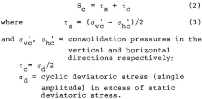
The cyclic triaxial strength is defined as the maximum shear (S ) at failure and is given by: 0 C I U O U T S I D E D Y K E a C A U O U T S I D E D Y K E C I U U N D E R D Y K E A C A U U N D E R D Y K E 4 0 - 20 - 0 I I I 1 I I I I I I 1 I I 0 20 40 6 0 80 100 120 140 160 180 200 220 240 260 p '
-
( ul' + u 3 ' ) 1 2 k P aFigure 4. Strength envelope from static triaxial tests
and uvA, ah; = consolidation pressures in the vertical and horizontal
directions respectively;
TC= Ud/2
ud = cyclic deviatoric stress (single
-
amplitude) in excess of static deviatoric stress.
Failure is defined as the development of
failure plane or a 10% double amplitude strain, whichever comes first.
The mode of failure in an isotropically consolidated undrained and symmetrical cyclic shear (ICUSC) test is very different from that in an anisotropically consolidated undrained and unsymmetrical cyclic shear (ACUUC) test. The strain time plot for a typical ICUSC test is shown on Figure 5. In the first few cycles, the strain is symmetrical, as is the applied cyclic shear. Upon further straining, however, extension strain exceeds compression strain, indicating the presence of modulus anisotropy, with the compressional modulus stronger than the extension modulus. This leads to a failure under an extension state. The strength of an ICUSC test, therefore, corresponds to an extension strength.
Figure 5. Strain-time plot of an ICUSC test
The strain-time plot of an ACUUC test is shown in Figure 6. The total shear stress ( T~
+
T ~ ) did not change in direction in this test. It remained in the state of passive shear and the resulting strain cycled exclusively in the compression domain. This leads to a compressional mode of failure, yielding a higher cyclic strength than that of the ICUSC test. The average ACUUC strength is about 90% higher than the ICUSC strength for this clay. Observations of unsymmetrical cyclic strength higher than symmetrical cyclic strength have also been reported by Seed and Lee (1969) and Lee (1979).Figure 7 shows the decrease of ICUSC and ACUUC strengths with respect to Nf, where Nf is the number of cycles to failure. Both strengths are normalized by the static isotropically consolidated undrained triaxial compression
Figure 6. Strain-time plot of an ACUUC test
1
ACUUC TESTS--.
RANGE FOR VARIOUS CLAYS. -
..
1
(LEE AND FOCHT, 1976)0 1
' " ' " ' " ' ' " ' " " ' - ' I ' ""UJ0 LO 100 1000 10 000
N O . OF C Y C L E S T O F A I L U R E
Figure 7. Triaxial cyclic strength for soil under dyke
strength. For comparison with existing information, the range of results for many soils summarized by Lee and Focht (1976) is shown on the same figure. This range is for saturated clays failing under symmetrical cyclic shear. Both strengths of the present clay seem to follow the general pattern of other clays, with the ICUSC strength lying close to the upper limit and the ACUUC above it. At Nf > 4, the ICUSC strength starts to drop below the static strength, while the ACUUC strength is higher than the static strength throughout the entire range of Nf values observed in the experiments.
The question now is which cyclic strength should be used for design or analysis. More common in earthquake loading is the simple shear condition, which is different from the compression or extension condition. For clays, there are very few comparisons between cyclic shear strength and cyclic triaxial compression or extension strength. The results of Thiers and Seed (1969) showed, for San Francisco Bay mud, that there is no difference between simple
shear cyclic strength and unconsolidated
undrained cyclic triaxial strength of specimens trimmed at 45' from the vertical. Both
strengths, however, are about 20% higher than the cyclic strength of specimens trimmed in the vertical direction, the usual direction for the majority of tests recorded in the literature. Lee's (1979) work on a Champlain Sea clay shows that the ICUSC strength is higher than the simple shear cyclic strength at Nf < 10 and the
opposite is true at N f >
-
10. The ACUUCstrength is invariably higher than the simple shear cyclic strength. There is a need for further research along this line.
For the time being, the pseudo-static analysis coupled with Seed's (1979) criterion (Table 11) may be applicable to the present case. The criteria are based on acceptance of limited deformation and a crest acceleration less than 0.75 g. The unsymmetric dynamic strength due to earthquake loading is assumed not to drop below 85% of the static undrained strength, a condition which is satisfied with the present soil.
TABLE 11. Design Criteria for Pseudo-Static Analysis (after Seed, 1979) Earthquake
magnitude Design criteria
FS = 1.15 for seismic
coefficient = 0.1
FS = 1.15 for seismic
coefficient = 0.15
Resonant column tests
Six tests were performed on material obtained from below the dyke and seven tests on material from outside the dyke. The shear modulus (G,)
-
and the average peak shear strain (y ) were
deduced using the method by Drnevich et a1 (1978). The results for the low amplitude tests are shown in Table 111; the marine clay
from under the dyke had a mean initial modulus
(Gro) of 40.0 MPa at a mean y value of
- -
0.0066%. This compares well with the field crosshole test value of 40.5 MPa at a
comparable strain level. Such a good agreement indicates the high quality of the Osterberg samples. Samples from outside the dyke, consolidated to the same 150 kPa confining pressure for the same length of time, have a Gro value of 36.5 MPa at a mean yr value of 010067%. This Gro value is within 10% of that for soil from under the dyke.
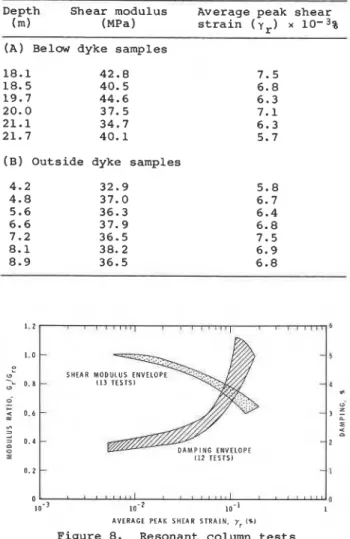
Figure 8 shows the change in shear modulus and
damping with increasing shear strain. In the strain range from 0.006% to 0.2%. normalized shear modulus values decrease about 40%. Damping increases from 1.75% to about 5.25% in the same strain range. No difference in behaviour is noted between samples from under
TABLE 111. Resonant column test results
Depth Shear modulus Average peak shear
(m) (MPa) strain (Yr) x 10-3%
(A) Below dyke samples
(B) Outside dyke samples
S H E A R M O D U L U S E N V E L
112 T E S T S 1
010.' 0 0
1 0 - 2 10.' A V E R A G E P E A K S H E A R S T R A I N . yr I01
Figure 8. Resonant column tests
and outside the dyke. All results fell within
the envelopes shown in Figure 8.
Deformational characteristics
A stress-strain model is required for the analysis of deformation or serviceability of
the dyke during earthquake loading. A model is
used here to describe the characteristics displayed in the resonant column and the symmetrical cyclic shear (ICUSC) tests. There are three aspects to this model: 1) first
cycle modulus (G ); 2) modulus degradation;
1
3) formation of residual strain. The definition of symbols is shown in Figure 9.
The first cycle shear modulus (G ) can be
1 represented by a Ramberg-Osgood model
(Richart, 1975). Expressed in terms of cyclic
deviatoric stress (a ) and static undrained
d
strength
(sU)
the model can be written as:W E A R STRAIN
+
Figure 9. Symbols used in the proposed model.
where R and a are parameters of the model and Go is the initial shear modulus, which can be obtained in this case either from the seismic crosshole or the low amplitude resonant column test, since both give the same value.
For the resonant column test, the term
2
is- given by:
-
G1If the model applies, a plot of log
-
G. I
versus log
1 1
will yield a straight linewith the intercept equal to log and the
slope to R
-
1. Figure 10 shows the testresults plotted in this manner and a straight line seems to provide a reasonable fit. a is 13.69 and R is 6.17.
Modulus degradation is the term describing the decrease of modulus during cyclic loading. It may be attributed to pore pressure increase with strain and the deterioration of the clay structure during cyclic straining. This degradation has been observed and studied (Aisiks and Tarshansky, 1969: Castro and
Christian, 1976). For San Francisco Bay mud
sheared at low cyclic strain level (f.04%), Idriss et a1 (1979) proposed that:
where GN is the shear modulus at the Nth cycle and t is the degradation parameter. While the degradation at such a low strain level has not been studied for the present soil, a different relation is proposed here for the degradation at higher cyclic triaxial strain
levels (20.1% to 22%) :
Gn
-
= 1-
6 log NG1
O C Y C L I C T R l A X l A L - O R E S O N A N T C O L U M N 0 . 6 -
-
-
0 . 4-
9 0 . 2-
-
l o g u d 1 2 5 ,Figure 10. Determination of deformation model parameters from cyclic triaxial and resonant column tests
where f3 is a degradation parameter. For
strain level exceeding +2%, failure is imminent and a stability consideration is more
appropriate.
0 for the given test series
(01
= 150 kPa) is aI;
function of the cyclic stress level. The empirical relationship can be approximately given by:
The residual strain (c ) is the average value
between the maximum and minimum strains
during a cycle of loading. It is a measure of the strain shift of the centre of hysteresis loop (Figure 9) from the origin, i.e., the permanent deformation after the cyclic shear stops. The amount of residual strain depends on soil type, stress level, number of cycles and testing method. The value of cr is theoretically zero for a cyclic simple shear applied along a plane free of initial or static shear. Some non-zero values, however, were noted by Moriwaki et al. (1982) partly because of the difficulty of maintaining perfect cyclic stress symmetry during the experiment. In the
ICUSC test, higher E- will be expected because
L
of straining in an anistropic material, as discussed earlier. Ideally the test should be conducted with proper recognition of the direction of principal stresses in the field with respect to the direction of the seismic shear. For the triaxial cyclic test data a simple approximate relationship is:
where A and B are parameters depending on soil type, stress level, and consolidation stresses. More data are required to clearly determine the values. A similar relationship was also observed by Marr and Christian
(1981).
SUMMARY AND CONCLUSIONS
In situ and laboratory tests were conducted on a Champlain Sea clay under and outside an earth dyke. The in situ work consisted of seismic crosshole tests, field vane shear tests and soil sampling. The laboratory tests included determination of Atterberg limits, together with consolidation, static triaxial, cyclic triaxial and resonant column tests.
The results show that the weight of the dyke has caused a significant consolidation in the clay, changing it into a normally consolidated clay. Associated with this change are an increase in undrained shear strength and a reduction of sensitivity. The static strength parameters, in terms of effective stress, however, remain unchanged under the dyke. The majority of the dynamic tests were conducted on clay from under the dyke; the results can be summarized as follows:
(1) The laboratory resonant column tests yielded an initial shear modulus of 40.0 kPa, which is the same as the value obtained in the field using the seismic crosshole technique. The ratio of initial shear modulus to undrained shear strength is 600. When consolidated under the same pressure, the clay from outside the dyke yields similar results in shear modulus and damping ratio.
(2) The 127 mm diameter Osterberg sample produces excellent quality samples for study of dynamic soil behaviour.
(3) An extension failure mode prevails in the
isotropically consolidated, symmetrical cyclic triaxial (ICUSC) tests, while
compression mode of failure predominates in the anisotropically consolidated,
unsymmetrical cyclic (ACUUC) tests. As in the static case, in which the compression strength generally exceeds the extension strength, the ACUUC strength is 90% higher than the ICUSC strength.
( 4 ) A model is proposed to describe the
deformational characteristics of the soil. The model has three components to deal with 1) the variation of first cycle modulus with stress or strain level, 2) modulus degradation with number of stress cycles, and 3) residual strain or permanent strain with stress cycles.
ACKNOWLEDGEMENTS
The authors gratefully acknowledge the efforts of A. Laberge and T.J. Hoogeveen, both of the National Research Council of Canada and A. Morton of Ontario Hydro, for carrying out the field work.
This paper is published with the joint approval of the Director of the Division of Building Research, National Research Council of Canada and the Directors of the Research and the Design and Development Divisions of Ontario Hydro.
REFERENCES
Aisiks, E.G. and Tarshansky, I.W. (1969) Soil studies for seismic design of San
Francisco Transbay Tube. ASTM STP 450 Vibration Effects of Earthquakes on Soils and Foundations, 138-166.
Bozozuk, M. (1977) Evaluating strength tests from foundation failures. Proc. 9th ICSMFE 1, 55-59 Tokyo.
Bozozuk, M. and Leonards, G.A. (1972) The Gloucester test fill. ASCE Specialty Conf. on Performance of Earth and
Earth-Supported Structures, (I), 299-317 Lafayette, Indiana.
Castro, G. and Christian, J.T. (1976) Shear strength of soils and cyclic loading. ASCE J. Geot. Engg. Div. (102) GT 9, Sept. 887-894.
Drnevich, V.P., Hardin, B.O. and Shippy, D.J. (1978) Modulus and damping of soils by the resonant column method. ASTM STP 654 Dynamic Geotechnical Testing, 91-125.
Hardin, B.O. and Music, J. (1965) Apparatus
for vibration of soil specimens during the triaxial test. ASTM STP 392 Instruments and Apparatus for Soil and Rock Mechanics, 55-73.
Idriss, I.M., Dobry, R. and Singh, R.D. (1979) Nonlinear behaviour of soft clays
during cyclic loading. ASCE J. Geot.
Engg. Div. (104) GT 12, December, 1427-1447.
Law, K.T. (1985) The use of field vane test under earth-structures. Proc. 11th ICSMFE, San Francisco.
Law, K.T., Bozozuk, M. and Eden, W.J. (1977) Measured strength under fills on sensitive clays. Proc. 9th ICSMFE, 1, 187-192 Tokyo.
Lee, K.L. (1979) Cyclic strength of a sensitive clay of eastern Canada. Canadian Geotechnical Journal (16) 163-176.
Lee, K.L. and Focht, J.A. Jr., (1976) Strength of clay subjected to cyclic loading. Marine Geotechnology (1). 3, 165-185.
Marr, W.A., Jr. and Christian, J.T. (1981) Permanent displacements due to cyclic wave
loading. ASCE J. Geot. Engg. (107) GT 8,
August, 1129-1149.
Moriwaki, T., Idriss, I.M. and Doyle, E.H. (1982) Earthquake-induced deformation of soft clay slopes. ASCE J. Geot. Engg. Div. (108) GT 11, November,
1475-1493.
Osterberg, J.E. (1952) New piston tube
sampler. Engineering News Record (1481, 77-78.
Richart, F.E., Jr. (1975) Some effects of dynamic soil properties on soil-structure
interaction. ASCE J. Geot. Engg. Div.
(101) GT 12, 1197-1240.
Seed, H.B. (1979) Considerations in the earthquake resistant desiqn of earth and
Seed, H.B. and Lee, K.L. (1969) Pore water pressures in earth slopes under seismic loading conditions. 4th World Conf. Earthquake Engg., 111, Season A5, 1-11 Santiago, Chile.
Thiers, G.R. and Seed, H.B. (1969) Strength and stress-strain characteristics of clays subjected to seismic loading conditions. ASTM STP 450 Vibration Effects of
Earthquakes on Soils and Foundations,
3-56.
rockfill dams. ~eotechniGue (29), 3,