CityCarControl: An Electric Vehicle Drive-by-Wire Solution for Distributed
Steering, Braking and Throttle Control
by
Thomas B. Brown S.B., C.S. M.I.T., 2009
Submitted to the Department of Electrical Engineering and Computer Science in Partial Fulfillment of the Requirements for the Degree of
Master of Engineering in Electrical Engineering and Computer Science at the Massachusetts Institute of Technology
May 2010
©2010 Massachusetts Institute of Technology All rights reserved.
Author
D$Part'meptof Electrical Engineering and Computer Science May 17, 2010 Certified by
Professor Kent Larson Thesis Supervisor Accepted by
\ \,.) Dr. Christopher J. Terman Chairman, Masters of Engineering Thesis Committee
~MASSACHUSETTS INSTITUTE
OF TECi 'LOGGY
I
DEC
16
2010
LIB
RARIES
ARCHIVES
CityCarControl: An Electric Vehicle Drive-by-Wire Solution for Distributed Steering, Braking and Throttle Control
by
Thomas Brown Submitted to the
Department of Electrical Engineering and Computer Science September 10, 2010
In Partial Fulfillment of the Requirements for the Degree of Master of Engineering in Electrical Engineering and Computer Science
1 Abstract
In this paper, we propose CityCarControl, a system to manage the steering, braking, and throttle of a new class of intra-city electric vehicles. These vehicles have a focus on extreme light-weight and a small parking footprint. In order to maximize maneuverability within a city environment, we show the feasibility of omnidirectional steering, and the integration of a folding chassis. Furthermore, we apply traditionally programming best-practice
techniques to simplify the design of the control system. Specifically, we present the concept of a modular, fail-silent wheel-robot with a standardized API responsible for controlling steering, braking and throttle within the vehicle.
Table of Contents
S A bstract ... 2
2 Introduction ... 5
3 Background ... 5
4 A pproach ... 6
4.1 DriveM ode Function ... 7
4.1.1 Standard Driving M ode... 8
4.1.2 0-T urn Driving M ode ... 9
4.1.3 FoldinMg M ode ... 9
4.1.4 Parked M ode ... 9
4.2 Safe hThrottle Function ... 9
4.2.1 Electronic Stability Control (ESC) M odule Description... 9
4.2.2 Traction Control System (TCS) Description ... 10
4.2.3 The Electronic Brake Force Distribution Module (EBFD) Description ... 10
4.2.4 Antilock Braking System (ABS) M odule Description... 10
4.3 SteerByW ire Function... 10
4.3.1 Standard Steering M ode ... 11
4.3.2 0-Turn Steering M ode ... 11
4.4 ThrottleByW ire Function ... 11
4.4.1 Standard Throttle M ode ... 11
4.4.2 0-Turn Throttle M ode...11
4.5 BrakeRegen Function ... 12
5 em ent ion ... om 12 5.1 Dom ain Com m unication ... 13
5.2 W heel Robot Design... 14
5.2.1 GeneralApproach...14
5.2.2 W heel API ... 1 5 5.2.3 Electronic Braking ... 16
5.3 Steering Algorithm Design ... 17
5.3.1 Steering Sim ulator ... 18
5.3.2 User Interface Requirem ents...18
5.4 Energy M anagem ent System ... 19
5.4.1 High Voltage Bus... 19
5.4.2 Batteries...19
5.4.3 M otor Controllers ... 20
5.4.4 Safety Sw itches ... 20
5.4.5 Low Voltage Bus...21
6 Conclusion... 21
7 A ppendix... 23
7.1 Block Functional M odules and Sensors... 23
7.2 Prelim inary Com m unication Flow ... 25
7.2.1 DriveM ode M essage Flow ... 25
7.2.2 SafeThrottle M essage Flow ... 26
7.2.3 SteerBy W ire M essage Flow ... 27
7.2.4 ThrottleByW ire M essage Flow ... 28
7.2.5 BrakeRegen M essage Flow ... 29
7.2.6 Infotainm ent M essage Flow ... 30
7.2.8 Safety M essag e Flow ... 3 1
7.2.9 BatteryMan Message Flow ... 31
7.2.10 Telema tics Link Message Flow...31
7.2.11 Autonomy Message Flow ... 31
7.3 A SIL D ecom p osition ... 3 2 7.3.1 DriveMode Function ASIL Decomposition ... 32
7.3.2 SafeThrottle Function ASIL Decomposition... 33
7.3.3 SteerByWire Function ASIL Decomposition... 33
7.3.4 ThrottleByWire Function ASIL Decomposition ... 33
7.3.5 BrakeRegen Function ASIL Decomposition... 33
7.3.6 Infotainment Function ASIL Decomposition... 34
7.3.7 Body Systems Function ASIL Decomposition... 34
7.3.8 Canopy Function ASIL Decomposition...34
7.3.9 FoldBy Wire Function ASIL Decomposition ... 34
7.3.10 Safety Function ASIL Decomposition...34
7.3.11 BatteryMan Function ASIL Decomposition ... 35
7.3.12 Telema tics Link ASIL Decomposition ... 35
7.3.13 Autonomy Function ASIL Decomposition ... 35
2 Introduction
With increasing urbanization worldwide, city streets are becoming ever more crowded and parking spaces are becoming more difficult to obtain. It is clear that a radical rethinking of the current automobile industry has become necessary. One solution to this growing
problem is Professor Bill Mitchell's CityCar implemented as a fleet of lightweight electric vehicles that can be used in a one-way shared-use program within the city center.1 These
vehicles can be made very light-weight and can maintain a greatly reduced footprint if we allow for a reduction in maximum range and maximum speed. Furthermore, these
specialized vehicles provide for the capability of rapid charging, and because of the shared-use system, can hypothetically receive much more shared-use than their personal-shared-use counterparts. With the objective of allowing for efficient parking of the vehicles, we design them with the capability of omnidirectional steering as well as the capacity to fold in order to reduce their footprint.
In addition to meeting the novel demands of this new vehicle class, the drivetrain system must be demonstrably reliable and responsive to the user's interactions. Because we desire omnidirectional steering, adjustable vehicle dynamics and regenerative braking, a
traditional drivetrain presents many problems and obstacles to our parallel goals. Instead, we posit a drive-by-wire system composed of fail-silent, redundant wheels controlled by a simplified but powerful wheel API and a decoupled, modular user interface.
3 Background
The CityCar system provides the unique opportunity to redesign a vehicle from the ground up with a focus on sustainability and integration within the city's ecosystem. With this in mind, there are four main goals to consider: integrating with the city's power system, utilizing the "mobility internet", deploying with a one-way shared-use model and basing the vehicle on an electric drive system with a drive-by-wire control system. 2
The vehicle should take advantage of the infrastructure of the city. As electric vehicles become more common, it is clear that manufacturers are moving towards a standard connector for rapidly charging vehicles from the city's power network. By integrating with this system, the vehicle can reduce charge times and take advantage of the more economical and environmentally friendly power generating techniques that power cities in general. The "mobility internet" is made possible by the ease of a pervasive internet connections coupled with the low cost of computation. CityCar vehicles are conceived to be intelligent and capable of communication with each other as well as with the infrastructure of the city. This communication allows a wide variety of advantages including dynamic pricing, smart insurance, and even autonomous driving and parking.
1 Reinventing the Automobile -Personal Urban Mobility for the 21st Century.
William
J.
Mitchell, Christopher E. Borroni-Bird and Lawrence D. Burns 2 Reinventing the Automobile -Personal Urban Mobility for the 21st Century. WilliamJ.
Mitchell, Christopher E. Borroni-Bird and Lawrence D. BurnsFinally, the vehicle's drive-by-wire control system allows for the removal of several mechanical components, facilitating the independent maneuvering of each wheel, and the decoupling of the user interface. Furthermore, drive-by-wire permits the vehicle to be a simple platform for autonomy, opening the vehicle up for a myriad of different applications including automated towing, self-parking and remote driving. 3
There has been significant research along the lines of drive-by-wire systems within the last ten years. For example, GM produced an entirely drive-by-wire vehicle entitled the Hy-wire which demonstrated the ease of customizing the user interface of electronically controlled vehicles.4 Furthermore, modern hybrids like the Toyota Prius and the Nissan Leaf use throttle-by-wire systems that have proven safe and effective in a mass market. However despite the many advantages of drive-by-wire, there has yet to be a paper looking at the specific problem of dealing with a wheel-robot based distributed-drive vehicle.
4 Approach
We break the drive-by-wire system up into several functional modules. In Figure 1 we describe the basic interrelations of these modules. These functions are then spread across electronic control units (ECUs) in such a way as to maintain fast close-loop control between sensors and actuators that need to react quickly.
3 Reinventing the Automobile -Personal Urban Mobility for the 21st Century. William
J.
Mitchell, Christopher E. Borroni-Bird and Lawrence D. Burns4 Chernoff, Adrian. "The 2003 Hy-wire Concept Car". Ideation Genesis, LLC. Retrieved
Drivetrain Functional Modules
Figure 1 -Drivetrain functional modules and their associated actuators and sensors.
In the above model, we use the Joystick Controller to relay Angle X and Angle Y readings to the SteerByWire and ThrottleByWire functions. In the joystick scenario, Angle X and Angle Y correspond to horizontal and vertical movement of the joystick respectively. However, due to the modularity of the system. We are free to use any number of user interfaces. For example, with a classical steering system, the rotation of the steering wheel would
correspond to Angle X and the action of the gas and brake pedals would correspond to Angle Y.
4.1 DriveMode Function
The DriveMode function determines which mode the car should be in and relays
information that affects the behavior of the SteerByWire and ThrottleByWire functions. In order to determine the feasibility of state changes, the DriveMode function also monitors the status of folding and whether the vehicle is traveling forwards or backwards. The vehicle is always in exactly one mode, and for the purpose of safety, during transitions between modes both the throttle and steering is deactivated. Because of the complexity and length of time for the folding action to complete, we include both Folding and Unfolding as distinct but temporary modes. The different DriveModes that the car may be in are:
* Parked Mode
* Folded Parked Mode * Standard (Driving) Mode
e Reverse Standard (Driving) Mode
- Folded Driving Mode (Limited Speed)
- 0-Turn Mode
e Folded 0-Turn Mode
- Folding Mode - Unfolding Mode
The state flow controls is displayed in Figure 2. Note that the vehicle must be parked to initiate folding.
Drive Mode States
Unfolded
Standard DrivingFolding Parked O-Turn Driving
Parked _0-Turn Driving
Unfolding N*. Standard Driving
Folded
Figure 2 -Possible states and transitions for the DriveMode function.
Because accurate reporting of the status of the folding is necessary for safe steering, the DriveMode module requires a reliable connection to the folding sensors.
Additionally, the DriveMode module requires a reliable, fast connection to all mission-critical driving inputs provided by the driver. These include:
e Angle X - Angle Y - Fold Button - 0-Turn Button e Driving Button e Reverse Button e Park Button
4.1.1 Standard Driving Mode
When in Standard Steering, the full range of the joystick is mapped to the current safe wheel range determined by the SteerByWire function described in section 4.3. This safe range based on speed and road conditions and allows for small course corrections while traveling at high speeds; steering angle adjustments become more limited as speed increases.
In order to avoid stability problems, speeds are further limited when in Folded Driving mode, as the center of mass of the vehicle is higher. Further study is necessary to properly measure the effects of folding upon the vehicle dynamics of the car.
4.1.2 0-Turn Driving Mode
0-Turn steering allows the car to rotate in place around its central axis. The car must have come to a complete stop before it can transition in or out of 0-Turn steering mode.
4.1.3 Folding Mode
Folding mode is the temporary mode that the car is in while it is in the process of folding. The car must be in Parked Mode in order begin folding. After folding has completed, the car returns to Parked Mode.
While in the process of folding, all steering is disabled, and the wheels are set to directly forward, as it is in Parked Mode. The throttle is automatically engaged to assist in the folding action, and the brakes are activated for the front two wheels.
4.1.4 Parked Mode
In Parked Mode, the car's brakes are engaged, the throttle is disabled, and the steering of each wheel is locked in the forwards-facing position. This allows the vehicle to maintain a minimal footprint and also facilitates static parking when using a wheel with a caster system. Casters allow the wheels to maintain fail-silence in the event of a loss of power to the steering system, and are discussed in more depth in section 5.1.
Before the vehicle may enter Parked Mode, all wheels must come to a complete stop. If the user tries to enter Parked Mode while the car while moving, a message is displayed alerting them to park the vehicle first. The user may cancel the folding process while the vehicle is being folded, in which case the vehicle begins the unfolding process.
4.2 SafeThrottle Function
The goal of the SafeThrottle function is to develop a situation-adaptive system for drive and braking support. The system increases the vehicle's safety by detecting situations where a loss of traction is imminent and then either warning the user or intervening in brake or drive functions.
Because the physical dimensions of the vehicle change when folded, the SafeThrottle function needs to have awareness of the current state of the DriveMode module. The function is broken into four subsystems:
- Electronic Stability Control
e Traction Control
* Electronic Brake Force Distribution
e Antilock Braking System
4.2.1 Electronic Stability Control (ESC) Module Description
The goal of the Electronic Stability Control Module is to improve the vehicle stability by detecting and minimizing skids. The ESC module works in the background and continuously monitors the car's steering and vehicle direction as determined through sensors measuring the vehicle's lateral acceleration, vehicle rotation (yaw) and individual wheel speeds. A description of the major sensors and their interrelations can be found in the appendix section 7.1.
When the ESC module detects that the vehicle is in a skid, it applies the brakes asymmetrically, realigning the vehicle with the desired angle.
4.2.2 Traction Control System (TCS) Description
The Traction Control System monitors all four wheels and detects if an individual wheel is turning at a different rate than the others. When this loss of traction begins to occur, the TCS adjusts the power to that wheel until it has matched the turn rate of the other wheels.
4.2.3 The Electronic Brake Force Distribution Module (EBFD) Description
The Electronic Brake Force Distribution Module balances initial brake force over the front and back pairs of wheels during braking. This allows for significantly safer and gentler braking. Generally the front brakes are able to provide significantly more braking power, as they are driven down with some force during the braking process. However, this will be subject to the weight distribution within the vehicle as well. This final weight distribution will vary from vehicle to vehicle, thus directed study of the vehicle dynamics is necessary before the EBFD function's constants can be hard coded. Alternatively, weight sensors within the wheel robots' suspension could allow for dynamically setting the EBFD at the
cost of additional expense and complexity.
4.2.4 Antilock Braking System (ABS) Module Description
Each Antilock Braking System Module monitors an individual wheel for signs that the wheel is about to lock up. A locked wheel can stop spinning much more quickly than a car can decelerate even under optimal conditions. The ABS module observes wheel speed for signs of locking and when triggered reduces braking until the wheel begins accelerating again. For optimal behavior, this module must have very tight loop control with the braking module of the wheel robot.
4.3 SteerByWire Function
With a steer-by-wire design, there is a complete physical decoupling of the steering controls and the steering actuator. In order to allow intuitive steering, the vehicle's SteerByWire Function provides the user with force feedback based on force sensors and gyroscopes within the wheels and body of the car. For more details, see section 7.1.
Based on inputs from the DriveMode function, the SteerByWire function may be in one of two modes:
e Standard Steering Mode e 0-Turn Steering Mode
These modes determine the relationship between the user's joystick input and the steering angles provided by the actuators.
When we describe wheel steering angle we use the following convention: A positive steering angle value signifies that the front of the wheel is pointing away from the chassis. A negative steering angle value signifies that the front of the wheel is pointing towards the chassis. Because the joystick presents a single point of failure, and a fault would lead to an extremely dangerous situation, great care must be taken to ensure fail safety in the joystick. By using a fail silent mechanical design in the wheel robots (such as a well-designed caster system,
discussed more in section 5.1), we can use the natural symmetry of the vehicle to produce redundancy from simply fail silent wheel robot units.
4.3.1 Standard Steering Mode
When in Standard Steering, the full range of the joystick is mapped to the current safe wheel range based on speed and road conditions. For example, the safe range of wheel steering angles when traveling at 60km/h is much smaller than the full range of wheel steering angles when traveling at 10km/h. This restriction allows for small course corrections while traveling at high speeds.
Additionally, there are two behaviors (sub-modes) that the vehicle may use for steering depending on the situation and the driver's preference:
e Two wheel frontal steering
- Four wheel mirrored steering
Two wheel frontal steering is generally what modern drivers expect from a steering system. However, four wheel mirrored steering gives the driver a tighter turn radius at low speeds.
4.3.2 0-Turn Steering Mode
0-Turn steering allows the car to rotate in place around its central axis. The angle of the wheels during an 0-turn steering maneuver is highly dependant upon the dimensions of the vehicle's chassis, thus the SteerByWire function must know whether the vehicle is folded or unfolded, and must therefore have reliable access to the state of the FoldByWire function.
4.4 ThrottleByWire Function
Like the SteerByWire function, ThrottleByWire interprets the user's inputs and based upon the current DriveMode, converts them into the appropriate output for the wheels.
As such, the ThrottleByWire function behaves differently based upon the possible modes of the DriveMode system described below:
- Standard Throttle Mode * 0-Turn Throttle Mode
4.4.1 Standard Throttle Mode
In standard steering, the vehicle may be traveling either forwards or backwards, as dictated by the DriveMode function.
The ThrottleByWire function monitors the speed of the vehicle, and always keeps it within the safe limits of the vehicle's stability. When the vehicle is folded, the maximum speed is reduced significantly.
The SafeThrottle function affects the ThrottleByWire function most directly when in standard steering mode.
4.4.2 0-Turn Throttle Mode
When in 0-Turn mode, the ThrottleByWire function translates the driver's inputs into clockwise or counter-clockwise motion of the car.
As in standard steering mode, the ThrottleByWire function monitors the vehicle's speed and prevents the vehicles from rotating at unsafe speeds.
4.5 BrakeRegen Function
The BrakeRegen Function determines how much braking power should come from the mechanical brake, and how much should come from the regenerative braking of the motor.
In order to avoid overcharging the batteries, BrakeRegen must have access to the charge status of the battery pack that it is recharging.
5 Implementation
In order to implement the described functions, we break the system into ECUs based upon their physical location necessitated by time-critical sensors-actuator loops. With this in
mind, we use the physical placement of the ECUs described in Figure 3. The general subsystems created by this organization are the WheelRobot, the Driving Algorithms, and the Energy Management System. We describe these systems in greater detail below.
High
Level Harness
Routing
Figure 3 -The different components of the CityCarControl system, as well as their wiring harness and layout within the physical body of the vehicle.
5.1 Domain Communication
One advantage of the CityCarControl system is that it integrates neatly with the other systems in a vehicle with a backbone/gateway structure like that described in Figure 4
---Control System Domains
Information Chassis Safety Energy Drivetrain
bSysterns Management
| cur
| Key
hloannrt oomr-- -lEcW are qup en two
Canpy ontolprocessors so MW c~rec tuneon conbe deantd
F
13Y an r4OePendr device.r-C-ame~Tw Oe01Men reodes w~n she
samne futvo"My,
Figure 4 -An example layout for communication between various control system domains.
The backbone/gateway structure described above is the common choice for vehicle systems because it prevents the broadcasting of superfluous messages to the system as a whole, while still limiting the amount of hardware necessary for full functionality and safety.5
We use CANBus for non-mission-critical functions, and FlexRay for mission-critical
functions that require deterministic-time response. The specifications of these protocols are beyond the scope of this paper.
5.2 Wheel Robot Design
As described above, a primary aspect of the CityCarControl system is the incorporation of steering, throttle and braking functions into each wheel robot. Thus great care must be taken to ensure both the safety and simplicity of design of each wheel robot.
5.2.1 General Approach
The design of the wheel robot maintains a focus on modularity. This allows us more easily develop physical connection of each wheel to the main system, and assists in system integration and testing.
Additionally, in order for each wheel robot to be capable of performing all the necessary time-critical reactionary adjustments on its own within the given time frames, they must maintain tight-loop control with their actuators. This means that the wheels should be given simple instructions as to their desired angle and their desired speed and the wheel itself must autonomously and optimally work to achieve those goals. This includes antilock braking, regenerative brake balancing and steering adjustments. The tight-loop control system also assists in rapid autonomous response times by providing a close coupling of the s Deliverable D2.2 -Conceptual Hardware Architecture Specification Kosinski, R.
J.
(2008).actuators, sensors and ECUs. Where there are less components to pass through, their tends to be less latency.
The modularity of each wheel also allows us to achieve fail-silence in each wheel robot. For the purpose of this document, we define fail-silence in accordance with EASIS as a module that upon encountering a fault goes into a "safe state" that cannot spread the problem to
other subsystems.67 Although it is beyond the scope of this paper, it is important to note that the greatest impediment to fail-silence in a wheel is the possibility of a catastrophic failure within the steering system. Our recommended solution to this is to implement a caster system which allows a depowered wheel to safely follow the remaining functional wheels. 5.2.2 Wheel API
We provide a simple API to the wheel that consists of the following four simple commands: setdesiredspeed
setdesiredangle update-battery-status getwheelstatus
By limiting the communication between the wheels, we great simplify the process of
debugging our system and also open the way for later wheel developers to provide their own compatible wheel robots, and later platform developers to utilize our wheel robots.
6 C. Temple, "Avoiding the Babbling-Idiot Failure in a Time-Triggered Communication
System," ftcs, pp.218, The Twenty-Eighth Annual International Symposium on Fault-Tolerant Computing, 1998
Drivetrain Function Allocation
Figure 5 -The allocation of various functions within the Drivetrain, as well as basic communication flow. Figure 5 depicts the allocation of the various functions, along with the message passing between the Control Algorithm ECU and the Wheel Robots. As one can see, there are four basic messages that are passed between the two groups.
5.2.3 Electronic Braking
The braking system of the wheel must take into account two important factors. One is the automatic balancing of the braking between the mechanical brake force and the
regenerative electronic brake force provided by the reverse-driving of the wheel's main drive-motor. The other is the initiation of the antilock braking function built into the wheel. In our system we describe these functions as the BrakeRegen and SafeThrottle function respectively.
The BrakeRegen function keeps track of the current state of charge of the battery packs as reported by the BatteryMan function. This prevents a possibly catastrophic thermal event from occurring due to the overcharging of the battery packs. The message flow presented in Figure 6 shows how the BrakeRegen function interacts and communicates with the other functions present.
5annryman
BrakeRegen Message Flow
Ww~leimiem
ti"Iea
ic.1 aram m Ini ftu orde toa @tek
=16MW D RNOOfSS8OV& TkW.
Figure 6 -A basic message flow for the BrakeRegen system. This depicts a single cycle within the communication bus.
The goal of the SafeThrottle function is to develop a situation-adaptive system for drive and braking support. The system increases the vehicle's safety by detecting situations where a loss of traction is imminent and then either warning the user or intervening in brake or drive functions. The ABS function monitors the spin of the wheel for signs that the wheel is about to lock up. A locked wheel can stop spinning much more quickly than a car can decelerate even under optimal conditions.8 When triggered, the ABS function reduces braking until the wheel begins accelerating again. As described above, for optimal behavior, this module must have very tight loop control with the braking module of the wheel robot and is therefore placed in the actual WheelRobot module.
5.3 Steering Algorithm Design
The steering algorithm provides the logic necessary to convert the user's simple inputs into the appropriate messages to each wheel robot.
8 Semmler, S., Isermann, R., Schwarz, R., and Rieth, P., "Wheel Slip Control for Antilock Braking Systems Using Brake-by-Wire Actuators," SAE Technical Paper 2003-01-0325, 2003.
5.3.1 Steering Simulator
The general approach to the steering algorithm focuses on modularity and testability. With this in mind, we created the control algorithm simulator, as seen in Figure 7. The simulator allows for debugging of the complex system, and also allows for the isolation of the user interface and wheel robot APIs.9
Figure 7 -A screenshot from the simulator found at http://mobility-server.media.mit.edu/drivetrain/car.html An example of how the simulator simplifies complex interactions is the implementation of the drive modes we described in Figure 2. In our simulator, they are controlled by a separate DriveModeAlg object that controls the actual DriveMode that the vehicle is in and presents methods that simulate the user requesting a mode change. By enclosing this logic and the state of the vehicle's DriveMode within a private object, we ensure that other functions cannot change the DriveMode unexpectedly or illegally. The data encapsulation and abstraction used further allow our simulator to provide a seamless interface between the user's inputs, and the API used for controlling the wheel robots.
5.3.2 User Interface Requirements
Through the decoupling of the user interface and the drive system, we gain the unique ability to explore with novel user interfaces. With that in mind, the only requirements we have are the ability to steer left and right, to adjust the throttle forwards and backwards, and change the vehicle's DriveMode. Because the user interface is a mission-critical system, it may make sense to use redundancy to achieve fail-tolerance. For example, in our
prototype we chose to use a pair of redundant joysticks as the primary user interface.
9 More screenshots, source code, and a link to the working simulator can be found in the Appendix.
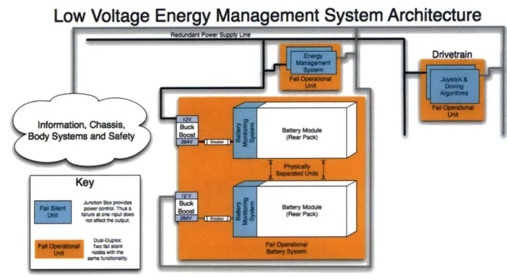
5.4 Energy Management System
The full extent of the vehicle's energy management system is beyond the scope of this paper. However, it is important to consider the redundancy necessary for safely operating the system using both the high-voltage and low voltage buses.
5.4.1 High Voltage Bus
In order to provide each wheel with an uninterrupted supply of power, and to allow for regenerative braking, we recommend the following architecture for the high voltage system within the vehicle:
High
Voltage Energy Management System Architecture
Figure 8 -An example architecture for the high voltage energy management system powering CityCarControl. 5.4.2 Batteries
The system's battery pack must achieve certain benchmarks with regard to the following criteria:
Form Factor Energy Power Voltage
Since we are developing under extreme constraints on size and weight, but also want the ability to rapid charge, the energy density and power density of the batteries are crucial.
5.4.2.1 Battery Form Factor
Each battery pack must fit in one of the compartments located between either the front wheels or the rear wheels. Further, they must be accessible for maintenance and
replacement. If the battery packs retain their charge properties for 1000 cycles, for high-use
vehicles (more than 5 recharges per day) we predict that battery replacement may be as common as once every six months.
5.4.2.2 Battery Energy
In order to provide the desired maximum range of 60 km in a loaded vehicle, we estimate that t at least 10 kW-h of energy must to be contained within the vehicle's batteries.
5.4.2.3 Battery Power
To provide power to the Powertrain and to all subfunctions of the vehicle, we need to be able to draw up to 30 kW from the batteries for peak operation.
Additionally, in order to charge the battery packs within 15 minutes, they need to be able to absorb 40kW when rapidly charging. This may require additional cooling during the
charging process.
5.4.2.4 Operating Voltage
Higher voltages allows for thinner wires and less energy loss throughout the wiring of the system. However, limitations are imposed by both the chemistry of the battery packs, and the operating voltages of the drive motors.
We suggest a maximum operating voltage of 264 V for each of the battery packs in the battery system. Further, we suggest that between 160V and 240V be used on the main high voltage bus. During the lifetime of the battery packs, their operating voltage will decrease from their initial operating voltage. By setting the voltage of the bus to significantly lower than that of the battery, we can use a unidirectional buck-boost converter, simplifying the system and allowing for cost savings.
Assuming the use of a unidirectional buck-boost converter, and a maximum battery pack operating voltage of 264V, there is a tradeoff to be considered when determining the operating voltage of the drivetrain system:
e A higher voltage (-240V) will allow the system to operate more efficiently for some
time. However, as the battery pack degrades, it's voltage will decrease to 240V fairly quickly.
e A lower voltage(-160V) would allow the battery pack to last longer, as more
recharge cycles can take place before the battery voltage will be reduced to 160V. However, more energy will be lost in the wires running through the system, and late stage batteries may have significantly worse total energy stores.
We recommend an operating voltage of 200V in order to provide a good balance between these competing goals.
5.4.3 Motor Controllers
We will be using Reductive Controllers to power the drive motors in each wheel robot. This
MCU also functions as a rectifier or inverter, allowing us to use three-phase AC current to
charge the batteries. 5.4.4 Safety Switches
We have a set of safety switches that are used in the case of a fault such as a soft-short to minimize damage.
5.4.5 Low Voltage Bus
The low voltage bus provides power to all systems that operate near 12 Volts. For the purpose of redundancy, we create two redundant low voltage power buses that share no connection point. These independent buses allow us to ensure fail operability of the mission critical ECUs.
nent System Architecture
Figure 9- An example architecture for the low voltage energy management system powering CityCarControl.
6 Conclusion
Through our investigation of the CityCarControl system, we have laid the foundation for a drive-by-wire solution that allows vehicle designers to create a product with adjustable vehicle dynamics, omnidirectional steering, regenerative braking, chassis folding and
customizable user-interfaces. We believe that by applying popular programming best-practices like data-abstraction and message passing, we can greatly reduce the time, expense, and complexity of designing vehicles incorporating myriad novel features. Furthermore, through the simulation and the partitioning of the system into the logical subcomponents we have described, we believe that we can greatly reduce the length and complexity of the subsequent development process of said vehicle.
We foresee three important areas of future study stemming from the work presented in this paper. Generally these three areas correspond to the user interface, the vehicle dynamics, and the safety system. We describe each problem below, and give suggestions for further research.
As we described early in this paper, one of the advantages of a drive-by-wire system is its flexibility with regard to various user-interfaces. However, with this broadening of possibilities comes the responsibility of evaluating the usability and safety of these new
user-interfaces. Thus we suggest that a further area of study is the development of sensible user interfaces to allow for usability and universal accessibility.
The vehicle dynamics of the system are another area that must be properly evaluated. By allowing the vehicle to fold, we force designers to consider the dynamics and properties of both a folded and an unfolded vehicle. However, by controlling each wheel independently we gain the ability to dynamically adjust the vehicle's handling capabilities on the fly. The ramifications of this shift in design warrant further study but are beyond the scope of this paper.
Finally, an in depth safety analysis of CityCarControl is necessary before it may be used in commercial production. As a starting point, we present our basic hazard analysis along with Automotive Safety Integrity Level (ASIL) decompositions in section 7.3 of the attached appendix.
7 Appendix
Key
enock
Sensor
Block Functional
Modules and Sensors
* mpact Safety ensors RADAR Autonomy~ ~~uA LIDAR GPS Telematics SStektttng connntcoo Latnora SafeThrottle Snvsorsu ThrottteByWre BrakeRegene Contr ~ Jo, Sensors FoldByWire BatteryMan ient ALocks B ody Primary Actuators and Sensors 24
Figure 10 - This diagram provides a complete picture of the major functional modules and their primary actuators and sensors.
7.2 Preliminary Communication Flow
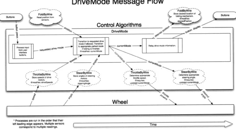
We present some preliminary solutions for the communication flow of the functions of the vehicle. Processes on the left of the diagram begin first and progress sequentially to the right of the diagram. These diagrams may serve as a template for the development of a fully functional system implementing CityCarControl
7.2.1 DriveMode Message Flow
DriveMode Message Flow
_________Control Aorithms DrivMods pFF g 0 lv Tv currsti~ode ~~dOM *~.~ *'n Ld rwkx~e Omfeamm Wheel
* Processes are ru in the order that thek
left aing edge appears. Mute sensors
correspond ruttoIe reading.
I
I Figure 11 0r -
in* Vhf.001-7.2.2 SafeThrottle Message Flow
SafeThrottle Message Flow
Control Algorithms SteerByW e C ec k 4 *e ic i
aN ucxed -- ior angles r are fad n .-diid.*0 power"a
-- rame nnel
ThrottleByWire
hrottle~yre Che a A aseels arde
Sequires:wee wheel 0 n a!rear ,
-sds .pdated speeds samespeedif not hi r n imtl~cionii5/ aseen ast
Wheel
* Processes are run in the order that their left leading edge appears. Multiple sensors
correspond to multiple readings, Time
7.2.3 SteerByWire Message Flow
SteerByWire Message Flow
Control
Algortthms
mad
---SetT nowi
dsu'.dgf
calumm0~ch~* -leA
sft
Wheel
Ouv
of
rrmrinr
%f -i ged apm. Moie m nr m
7.2.4 ThrottleByWire Message Flow
ThrottleByWire Message Flow
Control Algorithms
wh~ee p4
SafeThrottle -polypower Z-UE7r to
j- - ujstments wheel P
Autonomy
CCalculat
Dtive!Vode - drive mode cespwee'oe
for e I-P Wheel Poitveorneaa pwrdetiines rrakougeor deving. ccurate cuw wneel speed. co wm pow Aa oae rea . 9
ivo Drive Toru-Dv Mt Drive Torque
odor Gug Guage
-Processes are run in the ordr that tHeit
eft leadi'N edge appears. Multiple Sersors Time correspond to multiple readings :.e
7.2.5 BrakeRegen Message Flow
BrakeRegen Message Flow
Control AlgorithmsWheel
corespondon~ toV &uweeradns
Figure 15
1,ThrogM
.p
4-On eg appears.
Mu*soI-'-correspond lo mufle mmWVL Tinm
Figure 15
7.2.6 Infotainment Message Flow
Infotainment Message Flow
CAN BackBoneInfotainment update appropriate
dsplayMode models: eg speed
Proess all CAN traffic - 5ae 5 nmraar, safety
pare updates toe verncie state.
Charges the current
Urcwnal of the
Screen.
dispayoce based ob e d Splav nmadi Se
soaec touch handler: < CdelayMd I
Render Sceen
Touchscreen Display
* Processes are run in the order that tneireft leading edge appears. Multiple sensors T__me
correspond to multiple readings.
Figure 16
7.2.7 FoldByWire Message Flow
FoldByWire Message Flow
Control Algorithms
DriveMode
Folding
/Cr
ipara dseposition p mi n "'3"I
Prongseent ari r n t aortor I
Folding Folding
*Processes are run sn thre order that their left leading edge appears. Multiple sensors
correspond to multiple readings Time
7.2.8 7.2.9
Safety Message Flow BatteryMan Message Flow
BatteryMan Message Flow
cont Alorithms
we
P ross in ft Nwrdir Wi Inki
MRWOpWft~~qPM WWM
onuqnu 0*1 ff, TkW
Figure 18
7.2.10 Telematics Link Message Flow 7.2.11 Autonomy Message Flow
Autonomy Message Flow
Control Algorithms
DriveMode SteerByW re ThrotleByWire
---/ --- / --- ---/
Autonomy Box (Implemented by MIT)
1DAR Telematics Unk
Processes are run in the order that their left leading edge appears. M Iliple sensors correspond to multiple readingsTre
Figure 19
7.3 ASIL Decomposition
For the purpose of determining the functional safety requirements of each function in the system, we perform a hazard and risk analysis on each.
For each possible hazard, we rate the severity of the hazard (S), the probability of exposure
(E), and the controllability of the hazard (C). Based off of these three estimations, we assign
each hazard an Automotive Software Integrity Level (ASIL) rating using the guidelines put forth in IS02626210
7.3.1 DriveMode Function ASIL Decomposition
There are several possible hazards related to the DriveMode function to consider. These include:
* A requested or unrequested transition out of Standard (Driving) Mode while driving at high speed. (S3 E4 C3 ASIL-D)
* An internal folding state change that does not reflect the actual folding state of the vehicle while driving unfolded at high speeds and cornering quickly. (S3 E4 C1 ASIL-B)
* An internal folding state change that does not reflect the actual folding state of the vehicle allowing the driver to travel at high speeds while folded. (S3 E2 C1 QM)
An unrequested transition out of Parked Mode while the vehicle is parked. (S2 E4 C2
ASIL-B)
7.3.2 SafeThrottle Function ASIL Decomposition
There are several possible hazards related to the SafeThrottle function to consider. These include:
- An unnecessary increase in braking power to one or more wheels due to a problem with the Electronic Stability Control or Electronic Brake Force Distribution functions when the vehicle is moving at high speeds. (S3 E4 C3 ASIL-D)
- An unnecessary decrease in throttle power to one or more wheels due to a problem with the Traction Control function when traveling at high speeds in traffic. (S3 E3 C2
ASIL-B)
- A failure in the initiation of antilock braking function leading to a single wheel's
brake locking. (S3 E4 C3 ASIL-D)
e A problem with the antilock braking function leading to all wheels' brakes failing to
activate. (S3 E4 C3 ASIL-D)
- A problem with the antilock braking function leading to a single wheel's brake failing
to activate. (SO E4 C3 QM, due to redundancy of the wheels) 7.3.3 SteerByWire Function ASIL Decomposition
There are several possible hazards related to the SteerByWire Function to consider. These include:
e A failure that causes one or more wheels to actively steer in an unrequested direction
while at high speed. (S3 E4 C3 ASIL-D)
e A failure to place one or more wheel at the appropriate angle during 0-turn. (S2 E4
C2 ASIL-B)
- A failure that causes all wheels to lose steering power and passively steer in an
unpowered state while at high speed. (S3 E4 C3 ASIL-D)
e A failure that causes one wheel to lose steering power and passively steer in an
unpowered state while at high speed. (SO E4 C3 QM, due to redundancy of the wheels)
7.3.4 ThrottleByWire Function ASIL Decomposition
There are several possible hazards related to the ThrottleByWire Function to consider. These include:
- A failure that causes one or more wheels to increase their throttle in an unrequested
manner. (S3 E4 C3 ASIL-D)
- A failure that causes one or more wheels brake in an unrequested manner. (S3 E4 C3
ASIL-D)
- A failure that causes one or more wheels to lose the ability to brake or drive as
requested. (SO E4 C3 QM, due to redundancy of the wheels) 7.3.5 BrakeRegen Function ASIL Decomposition
There are several possible hazards related to the BrakeRegen Function to consider. These include:
- A failure that causes a brake to continue to use regenerative braking after the
batteries are already full, leading to a thermal event and loss of steering control in at least two wheels. (S3 E4 C3 ASIL-D)
- A failure that causes braking to be impaired in a single a wheel. (S2 E4 CO QM, due to
redundancy of the wheels)
- A failure that causes one or more wheels brake in an unrequested manner. (S3 E4 C3
ASIL-D)
7.3.6 Infotainment Function ASIL Decomposition
There are several possible hazards related to the Infotainment Function to consider. These include:
e A failure that causes the rear-view video to fail while backing the car up. (S2 E3 C1
QM)
- A failure that prevents up to date diagnostic information from being displayed. (S2
E4 CO QM)
- A failure that causes the stereo system to suddenly become very loud. (S2 E4 CO QM)
7.3.7 Body Systems Function ASIL Decomposition
There are several possible hazards related to the Body Systems function to consider. These include:
e A failure that causes the headlights to go out while traveling at high speeds through
the dark. (S2 E3 C1 QM)
* A failure that causes the seat to adjust itself into an uncomfortable position while traveling at high speeds. (S2 E3 C1 QM)
e A failure that prevents the user from being warned of impending battery exhaustion,
resulting in loss of control. (S3 E4 C3 ASIL-D)
- A failure in the network management system that causes a component of the drive or
energy management systems to enter sleep mode when not requested. (S3 E4 C3
ASIL-D)
7.3.8 Canopy Function ASIL Decomposition
There are several possible hazards related to the Canopy Function to consider. These include:
e A failure that causes a requested or unrequested opening of the canopy while
traveling at high. (S3 E4 C2 ASIL-C) 7.3.9 FoldByWire Function ASIL Decomposition
There are several possible hazards related to the FoldByWIre Function to consider. These include:
e A failure that causes a requested or unrequested folding of the vehicle while
traveling at high. (S3 E4 C2 ASIL-C) 7.3.10 Safety Function ASIL Decomposition
There are several possible hazards related to the Safety Function to consider. These include:
A failure that causes the airbag to deploy unnecessarily while stationary (S1 E4 C3 ASIL-B)
* A failure that causes the airbag to deploy unnecessarily while driving (S3 E4 C3
ASIL-D)
* A failure that prevents the airbag from deploying during impact (S3 E4 C3 ASIL-D) 7.3.11 BatteryMan Function ASIL Decomposition
There are several possible hazards related to the BatteryMan Function to consider. These include:
e A failure that causes all four wheels to lose power. (S3 E4 C3 ASIL-D)
- A failure that prevents the driver from being notified of impending battery
exhaustion. (S3 E4 C3 ASIL-D) 7.3.12 Telematics Link ASIL Decomposition
There are several possible hazards related to the Telematics Link to consider. These include:
e A failure that causes the GPS system to fail. (SO E4 C1 QM)
* A failure that prevents the system from assisting the user with inter-vehicular communication. (SO E4 C1 QM)
7.3.13 Autonomy Function ASIL Decomposition
There are several possible hazards related to the Autonomy Function to consider. These include:
* A failure that causes the vehicle to lose control when driving autonomously in an occupied area and hit a bystander. (S1 E2 C3 QM)
* A failure that causes the vehicle to lose control when driving autonomously in a controlled environment and destroy property (SO E2 C3 QM)
7.4 Drivetrain Simulator Source Code
Processing Code capable of being run with the IDE found at www.processing.org or the tools at www.processingjs.org.
Live demo can be found at http://mobility-server.media.mit.edu/drivetrain/car.html. Here are screenshots of the system in action:
Figure 20
Roar Rioht acts champe Dexired Angles 49.7636416907261
Rear Left ZcUs Change Desired Angles -49.76364169072618 Front Ieft IEU: change Throttle: -52 percent of maX. Fro.t Right .. : Chage Thrttle: 52 percent of max. Rear Right .CUz Change Throttle: -52 percent of max.
Rear Left cDus Change Throttle: 52 percent of sax.
Figure 21 // Global variables float wheelOffsetX; float wheelOffsetY; float X, Y; float nX, nY;
boolean bover = false;
float sWidth, SHeight; //Car Components Chassis chassis; SteeringControlAlg steeringControlAlg; ThrottleControlAlg throttleControlAlg; DriveModeAlg driveModeAlg; Wheel wheelFL; Wheel wheelFR; Wheel wheelRR; Wheel wheelRL; WheelECU wheelECUFL; WheelECU wheelECUFR; WheelECU wheelECURR; WheelECU wheelECURL;
//Enumerate Driving Modes
int normalMode = 0;
int hurricaneMode = 1;
int foldingMode = 2; //Disables driving while in the process of
folding
int unfoldingMode = 3; //Disables driving while in the process of
folding //Colors
int bgColor = 124;
boolean messageMode;
Drive Mode Algorithm ECU Class
Determines active mode and sets the activeMode of the steering
Alg.
Singleton Pattern
class DriveModeAlg extends Node{ String name;
int currentMode;
int lastMode;
DriveModeAlg(String name){ super(name); this.name = name; this.currentMode = normalMode; this.lastMode = normalMode;
}
void run(){ checkfoldedstatus();}
void checkfoldedstatus(){if (currentMode == foldingMode && chassis.getlength() ==
chassis.foldedL){
currentMode = lastMode;
}
if (currentMode == unfoldingMode && chassis.getlength() ==
chassis.unfoldedL){
currentMode = lastMode;
}
}
void h mode(){
if (currentMode != foldingMode && currentMode !=
unfoldingMode){
currentMode = hurricaneMode;
print message("Activate Hurricane Mode");
}
}
void n mode(){
if (currentMode != foldingMode && currentMode !=
unfoldingMode){
currentMode = normalMode;
print message("Normal Hurricane Mode");
}
}
/*Bring wheels straight, fold, put wheels back into mode they were in before folding began.
Disable all inputs except unfold */ void fold({
printmessage("Activate Folding Mode");
if (currentMode == foldingMode){
//don't do anything return;
}
else if (currentMode == unfoldingMode){
//don't change lastMode
}
else{
//store the mode we were in before folding began
}
//set folding mode
this.currentMode = foldingMode;
checkfoldedstatus(); //are we already folded?
}
/*Bring wheels straight, fold, put wheels back into mode they were in before folding began.
Disable all inputs except unfold */
void unfold({
printmessage("Activate Unfolding Mode");
if (currentMode == unfoldingMode){
//don't do anything return;
}
else if (currentMode == foldingMode){
//don't change lastMode
}
else{
//store the mode we were in before folding began
lastMode = currentMode;
}
//set folding mode
this.currentMode = unfoldingMode;
checkfoldedstatus(); //are we already unfolded?
}
int getmode(){
return this.currentMode;
}
String get modestring({
if (get mode() == 0)
return "Normal Mode";
if (get-mode() == 1)
return "Hurricane Mode";
if (get mode() == 2)
return "Folding Mode";
if (get mode() == 3)
return "Unfolding Mode"; return "ERROR";
}
}
/*
Throttle Control Algorithm ECU Class Singleton Pattern
class ThrottleControlAlg extends Node{ String name;
float throttleInput;
super(name);
this.name = name;
}
void processinput(float throttleInput){
this.throttleInput = 1-(throttleInput/300); //between -1 and
1
}
void run(){
int driveMode = driveModeAlg.getmode();
if (driveMode==normalMode){ change throttle(this.throttleInputwheelECUFLdriveMode); changethrottle(this.throttleInputwheelECUFR,driveMode); changethrottle(this.throttleInputwheelECURR,driveMode); changethrottle(this.throttleInput,wheelECURL,driveMode);
}
else if (driveMode == hurricaneMode){
float scalar = .75;//reduce the throttle power by some
scalar changethrottle(-this.throttleInput*scalar,wheelECUFLdriveMode); change throttle(this.throttleInput*scalar,wheelECUFR,driveMode); changethrottle(-this.throttleInput*scalar,wheelECURRdriveMode); change throttle(this.throttleInput*scalar,wheelECURLdriveMode);
}
else{ change throttle(0,wheelECUFL,driveMode);changethrottle(0 ,wheelECUFR, driveMode);
changethrottle(0,wheelECURRdriveMode); changethrottle(0,wheelECURLdriveMode);
}
}
/*
Determine desired throttle based on throttle input and drive mode
void change throttle(float throttleInput, WheelECU wheelECU, int driveMode){
Wheel wheel = wheelECU.wheel; //Get the wheel associated with
the wheel ECU
wheel.setthrottle(throttleInput);
}
/*
Steering Control Algorithm ECU Class Singleton Pattern
*/
class SteeringControlAlg extends Node{ String name;
float steeringInput;
SteeringControlAlg ( String name) {
super(name);
this.name = name;
}
void processinput(float steeringInput){
this.steeringInput = steeringInput;
if (driveModeAlg.getmode() == foldingMode |
driveModeAlg.get mode() == unfoldingMode) {
//set all wheels to straight forwards
this.steeringInput = width/2; //set wheels straight
}
}
void run(){
int driveMode = driveModeAlg. get mode (;
printmessage("Current Mode is: "+driveModeAlg.getmode_string()); changesteering(this.steeringInputwheelECUFL,driveMode); changesteering(this.steeringInput,wheelECUFR,driveMode); changesteering(this.steeringInputwheelECURR,driveMode); changesteering(this.steeringInput,wheelECURL,driveMode);
}
//calculate the turn radius based on the current steeringInput float get turnradius(){
float trOffset=O, trCenterX=O, trCenterY=O;
if (driveModeAlg. get mode () == normalMode) {
//calculate desired turn radius
trOff set = turn_r adius( (this. steeringInput*2/width)-1);
trCenterX = trOffset;
trCenterY = chassis.carCenterY;
}
else if (driveModeAlg.getmode() == hurricaneMode) {
trCenterX = 0; //hack to put it in the right place
trCenterY = chassis.carCenterY;
}
else if(driveModeAlg.getmode() == foldingMode
driveModeAlg. get mode () == unfoldingMode) {
trOffset = turnradius((this.steeringInput*2/width)-1); trCenterX = trOffset; trCenterY = chassis.carCenterY;
}
return trCenterX;/*
Determine desired angle based on steering input and drive mode
*/
void change steering(float steeringInput, WheelECU wheelECU, int driveMode){
Wheel wheel = wheelECU.wheel; //Get the wheel associated with
the wheel ECU
if (driveMode==hurricaneMode){
float yOff = chassis.carCenterY-wheel.wheelCenterY;
float xOff = chassis.carCenterX-wheel.wheelCenterX;
float angle = PI/2-atan(xOff/yOff);
//hack to keep it pointing forward if(angle>(PI/2)){
angle = angle-PI;
}
//Send message with angle wheelECU.setangle(angle);
}
else{
float trOffset =
this.turn radius((this.steeringInput*2/width)-1);
float trCenterX = trOffset;
// trCenterX = turnradius(X)
float trCenterY = chassis.carCenterY;
float yOff = chassis.carCenterY-wheel.wheelCenterY;
float xOff = abs(wheel.wheelCenterX-chassis.carCenterX) +
trCenterX;
float angle = PI/2-atan(xOff/yOff);
//hack to keep it pointing forward if(angle>(PI/2)){
angle = angle-PI;
}
//Send message with angle wheelECU.setangle(angle);
}
// takes an input between -1 and 1, calculates turn radius.
// we let the minimum turn radius be 100px and the max be 10A12
float turnradius(float normSteeringInput){ if(normSteeringInput<0){
//make positive, change scale, then make result negative return -this.turnfunction(-normSteeringInput);
}
else{ return this.turnfunction(normSteeringInput);}
}
//maps [0,1] to [10A5,10A2]float turnfunction(float val){
float sensitivitybase = 10;
float sensitivityscalar = 3;
float offset = 2.3; //how tight is the closest turn radius?
//map [0,1] to [5,2] val=offset+sensitivityscalar-(val*sensitivityscalar); //use as exponent val = pow(sensitivitybase,val); return val;
}
II
Draws turn radii that show the turning range of the carvoid drawturnradii(){
float carCenterX = chassis.carCenterX;
float carCenterY = chassis.carCenterY;
float wheelOffsetX = chassis.wheelOffsetX;
float wheelOffsetY = chassis.wheelOffsetY;
float TR = steeringControlAlg.getturnradius();
//draw turn left and right radius based on calulated trCenter
II Draw inner turn radius
II Set stroke-color to grey
stroke(40);
strokeWeight( 10 );
// Set fill-color to clear
fill(0,0,0,0);
if(driveModeAlg.get mode() == hurricaneMode){
float wheelRadius= sqrt(pow(wheelOffsetX,2) +pow(wheelOffsetY,2))+10;
ellipse(carCenterXcarCenterY, wheelRadius*2,wheelRadius*2);
}
else{float leftTR = sqrt(pow((TR+wheelOffsetX),2)
ellipse(TR+carCenterX, carCenterY, leftTR*2,
float rightTR = sqrt(pow((TR-wheelOffsetX),2)
+pow(wheelOffsetY,2));
ellipse(TR+carCenterX, carCenterY, rightTR*2,
/*
Wheel Robot Class
class WheelECU extends Node{ float desiredAngle;
Wheel wheel; String name;
WheelECU(String name,Wheel wheel){ super(name);
this.wheel = wheel;
this.name = name;
}
Sets the desired angle, motor controller the rest.
leftTR*2);
rightTR*2);
should take care of
void set angle(float angle){
//we print this in degrees rather than radians for
this .print message( "Change Desired Angle:
"+str(angle*180/PI));
this.desiredAngle = angle;
clarity
//update steering MCU and receive updated position from it. wheel.set_angle(this.desiredAngle);
}
}
FlexRay Bus Class
Messages are sent over the Flexray network, all the nodes on the FlexRay bus receive all
the messages and write them to their FlexRay buffer. The Bus keeps track of all the nodes on it.
*/
ArrayList nodes;
Bus(String name, ArrayList nodes){ super(name);
this.nodes = nodes;
}
void write(Message message){
for (int i = nodes.size(-1; i >= 0;
//ArrayList doesn't know what it's cast it
i--) {
storing so we have to
Node node = (Node) nodes.get(i);
node.tobuffer(message); print_message(message+"");
}
}
}
/*
FlexRay Message Class
Messages are sent over the Flexray network
class Message {
Node fromNode; Node toNode; String command; float argument;
Message(Node FromNode, Node toNode, argument){
this.fromNode = fromNode;
this.toNode = toNode;
this.command = command;
this.argument = argument;
String command, float
FlexRay Node Class
Everything connected to the FlexRay bus with a FlexRay tranceiver is a FlexRay Node.
*/
class Node extends NamedObject {
ArrayList buffer; Node(String name){
super(name);
buffer = new ArrayList(; //set
}
void tobuffer(Message message){ buffer.add(message);
}
up an empty arraylist
void readbuffer(){
for (int i = buffer.size()-1; i >= 0; i--) {
//ArrayList doesn't know what it's storing so we have to cast it
Message message = (Message) buffer.get(i);
//figure out what to do with the message. this.process(message);
} }
/* For now, just print the message instead of processing it.
*/
void process(Message message){ printmessage(message+"");
} }
//////////////////////////////Wheels (and MCU abstracted
out)//////////IIIII///IIII//////////////
class Wheel extends NamedObject{ float wheelCenterX;
float wheelCenterY; float currentAngle;
float currentThrottle; //between -1 and
float maxSteeringSpeed = .1;//PI/180*5;
degrees per frame
Wheel(String name, float centerX, float super(name);//create the parent
this.wheelCenterX = centerX;
this.wheelCenterY = centerY;
this.currentAngle = 0;
this.currentThrottle = 0;
1
I/we can turn at 5 centerY){
void update folded_position(float centerY){
this.wheelCenterY = centerY;
}
Send desired angle to MotorController and receive actual angle back
*/
void set angle(float desiredAngle){ //figure out new current angle
float angleDiff = this.currentAngle - desiredAngle;
if(abs(angleDiff)<=maxSteeringSpeed){
this.currentAngle = desiredAngle;
}