HAL Id: hal-01461713
https://hal.archives-ouvertes.fr/hal-01461713
Submitted on 8 Feb 2017
HAL is a multi-disciplinary open access
archive for the deposit and dissemination of
sci-entific research documents, whether they are
pub-lished or not. The documents may come from
teaching and research institutions in France or
abroad, or from public or private research centers.
L’archive ouverte pluridisciplinaire HAL, est
destinée au dépôt et à la diffusion de documents
scientifiques de niveau recherche, publiés ou non,
émanant des établissements d’enseignement et de
recherche français ou étrangers, des laboratoires
publics ou privés.
On an efficient equalization structure for aeronautical
communications via a satellite link
Bilel Raddadi, Nathalie Thomas, Charly Poulliat, Marie-Laure Boucheret,
Benjamin Gadat
To cite this version:
Bilel Raddadi, Nathalie Thomas, Charly Poulliat, Marie-Laure Boucheret, Benjamin Gadat. On an
efficient equalization structure for aeronautical communications via a satellite link. 7th international
workshop on selected topics in mobile and wireless computing (STWiMob 2014) in 10th IEEE
Inter-national Conference on Wireless and Mobile Computing,Networking and Communications: WiMob
2014, Oct 2014, Larnaca, Cyprus. pp. 396-401. �hal-01461713�
O
pen
A
rchive
T
OULOUSE
A
rchive
O
uverte (
OATAO
)
OATAO is an open access repository that collects the work of Toulouse researchers and
makes it freely available over the web where possible.
This is an author-deposited version published in :
http://oatao.univ-toulouse.fr/
Eprints ID : 17187
The contribution was presented at WiMob 2014 :
http://easyconferences.eu/portfolio/wimob-2014/
To cite this version :
Raddadi, Bilel and Thomas, Nathalie and Poulliat, Charly
and Boucheret, Marie-Laure and Gadat, Benjamin On an efficient equalization
structure for aeronautical communications via a satellite link. (2014) In: 7th
international workshop on selected topics in mobile and wireless computing
(STWiMob 2014) in 10th IEEE International Conference on Wireless and
Mobile Computing,Networking and Communications: WiMob 2014, 8 October
2014 - 10 October 2014 (Larnaca, Cyprus).
Any correspondence concerning this service should be sent to the repository
administrator:
[email protected]
On an efficient equalization structure for aeronautical
communications via a satellite link.
Bilel RADDADI, Nathalie THOMAS, Charly POULLIAT, Marie-Laure BOUCHERET
University of Toulouse, INPT/ENSEEIHT, IRIT, France {vorname.name}@enseeiht.fr
Benjamin GADAT
Thales Alenia Space, Toulouse, France [email protected]
Abstract—In this paper, we investigate a sub-optimal but efficient receiver structure for the equalization of aeronautical communications via a satellite link. The structure is based on the inherent sparsity of the equivalent discrete baseband channel model that enables an efficient implementation based on simple parallel trellis using Maximum A Posteriori (MAP) detection combined with iterative residual interference estimation and cancellation. The proposed scheme is shown to be very efficient while significantly decreasing the complexity compared to a MAP receiver that does not exploit the sparsity of the aeronautical channel.
I. INTRODUCTION
Nowadays, UAV (Unmanned Air Vehicle) fly almost exclu-sively in reserved airspace. However, in the near future, several civil and military applications will require remote controlled aircrafts to monitor a very large civilian land area [1]. Some of the possible applications are environment surveillance and pollution detection or surveillance of energy, transportation and communications infrastructures. In this context, there is a growing interest for designing highly reliable and cost effective communication systems for both the command and the mission links.
The considered communication system is composed of three key links: land-aircraft, aircraft-satellite and satellite-aircraft. This paper will focus on the command link between the satellite and the aircraft. In fact, in the scenario considering for example UAVs controlled by satellite, it is essential to correctly model the link between the satellite and the aircraft to find appropriate solutions in order to fight against introduced distortions and to ensure a highly reliable signal reception. Generally, the studied link is composed of a line of sight (LOS)path with added multipath echoes coming from the ground and from waves scattered by the aircraft itself [2] [3]. The purpose of this paper is to make an efficient use of the channel properties of aeronautical communications to derive an enhanced structure for equalization. Based on the characterization of the aeronautical channel widely used in the literature, we study the discrete equivalent baseband channel. We show that under classical mild assumptions, this channel can be well represented by a “strong” sparse channel compo-nent plus some low power interference residual terms. Based on this model, a simple but efficient equalization structure is derived, that considers parallel trellis MAP receivers that are only matched to the sparse channel component. The residual interference term is iteratively mitigated by considering block
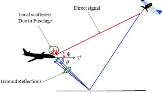
Fig. 1: Illustration of the geometry of the aeronautical com-munication channel.
based interference estimation based on hard outputs from parallel MAP equalizers followed by interference cancellation from the received signal at the input of the parallel equalizers. Note that sparse channel equalization has still been considered in several works [4]–[7], exploiting the sparsity mainly using parallel trellis based detection algorithm such as Viterbi or MAP algorithms. For equalization of zero padded sparse channels, the parallel MAP receiver is shown to be optimal [5], [6], [8]. For more general sparse channels, interference cancellation has been taken into account by introducing inter-trellis interference mitigation between parallel inter-trellis, but at the expense of additional complexity due to the need for proper scheduling [7], [9]. Several extensions of these works have been considered for application in turbo-equalization [6], [10], [11]. In this paper, the interference mitigation is completely revised to enable an easy and efficient implementation.
This paper is organized as follows. Section II summarizes the theoretical channel baseband model. The discrete equiva-lent baseband channel is derived and analyzed in Section III. Based on this analysis, the proposed structure for efficient equalization of the aeronautical channel is given in Section IV. Simulation results are presented in Section V and section VI concludes the paper.
II. BASEBAND CHANNEL MODEL
The aeronautical satellite channel is characterized by a strong line of sight (LOS) component that is present most
of the time. Depending on the type of terrain and the ge-ometry, multiple delayed reflections from the ground arrive at the aircraft with a certain attenuation compared to the LOS component. Furthermore local scatterers from the fuselage of the aircraft might deteriorate the signal as shown in Fig. 1. Especially the big surface of the wings of the aircraft may be the source of non-negligible scattered components.
For this type of channel, a model is proposed in [12]. it is composed of two main paths: a line of sight (LOS) path and a ground reflection (GR) path. For the LOS path, a large part of the signal arrives directly from the satellite, but another part also occurs from reflections on the surface of the aircraft. The complex envelope of the received signal for the LOS path can be written as follows:
yLOS(t) = [
p
PD+ αSCAT(t)] e2πjfLOS t x(t), (1)
where PD is the power of the direct component,αSCAT
rep-resents the fading due to local scattering,x(t) is the complex envelope of the emitted signal and fLOS is the Doppler shift
given by
fLOS =
vxcos(Ψ) + vzsin(Ψ)
λ ,
withλ the wavelength , (vx, vy, vz) the aircraft speed
coordi-nates andΨ the elevation angle (see Fig. 1).
Similarly, the complex envelope of the received signal for the GR path can be written as
yGR(t) = αGR(t) e2πjfGR t x(t − τGR), (2)
where the different terms have the following meanings and expressions:
• τGR is the delay spread given by the path difference
between the GR and the LOS paths divided by the speed of lightc. Based on geometrical considerations, we can derive it from the following expression
τGR= 2 H sin(θ)
c ,
whereH is the height of the aircraft above the ground and θ the incidence angle of the signal coming by ground reflections (see Fig. 1).
• αGR is the corresponding fading. Its expression
as-sumes that the arrival signal is a beam of many signals, each one arriving from an angleθk and corresponding
to an attenuation ak, a delay τGR + εk , where
εk ≪ τGR, and a frequency shift ∆fk = f (θk). If
fc is the carrier frequency, the expression is given by
αGR(t) =
X
k
ake2πj∆fkt e−2πj(τGR+εk)fct.
• fGR is the Doppler shift. It is the mean value of the
different frequency shifts∆fk and can be calculated
as
fGR= vxcos(θ) + vzsin(θ)
λ ,
where θ is the mean value of the different arrival anglesθk. According to [13],∆fkvaries according to
a Gaussian distribution centered onfGRfor a standard
deviation BGR
2 .
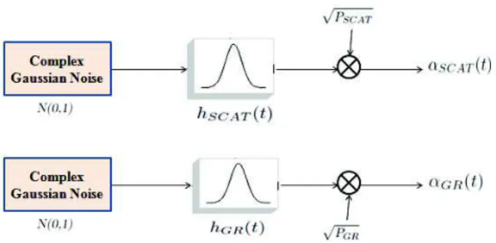
Fig. 2: Blocks generating αSCAT andαGR
As shown in Fig. 2, both fading componentsαSCAT and
αGR can be generated by filtering white Gaussian noises with
Gaussian filters whose impulsional responses can be written as: hSCAT(t) = exp(−π 2B2 SCAT 2 t 2) (3) hGR(t) = exp(−π 2B2 GR 2 t 2), (4) with BSCAT = 4 × α λ q
(vxsin(Ψ) + vzcos(Ψ))2+ (vysin(Ψ))2,
BGR= 4 × α
λ q
(vxsin(θ) + vzcos(θ))2+ (vysin(θ))2
α denotes the standard deviation of slope of the reflecting surface on the ground. The white Gaussian noise is assumed normalized. PSCAT andPGR respectively represent the
scat-tering path and the ground path powers. Assuming that the height of the aircraft in our coordinate system is constant (vz = 0), the Doppler power spectrum gets wider with
increasing elevation. This was confirmed by the measurements in [14] [15]. A last remark concerns the parameterα defined by [13] in his theoretical model. The largerα is, the rougher is the surface, the wider is the Doppler spectrum. Values around 0.07 or less are common. In fact the parameter alpha comes from maritime communications. A value of 0.07 assumes a sea surface with fully developed waves with a height of approximately4 m.
A block diagram summarizing a possible implementation of the aeronautical channel is given in Fig. 3. The upper path represents the LOS component including coherent multipath coming from local scatterers. The lower path represents the ground reflections composed of incoherent multipaths, assum-ing that all reflected components arrive within a short time interval.
Finally, considering both LOS and GR components, the impulsional response of the aeronautical channel can be finally written as follows:
Fig. 3: Aeronautical channel model where h1(t) = [ p PD+ αSCAT(t)] e2πjfLOSt, (6) h2(t) = αGR(t) e2πjfGRt. (7)
III. DISCRETE EQUIVALENT CHANNEL MODEL
A. Received signal
By calculating the correlation RHH(∆t) of the frequency
channel response H(t, f ) between two instants separated by ∆t, the coherence time Tcis the value giving ˜RHH(∆t) = K,
where ˜RHH(∆t) = |R
H H(∆t)
RH H(0) | is the reduced correlation term
andK, 0 < K < 1, is the required correlation factor. Since the signal arriving after reflection on the surface of the earth has a low power compared to the signal coming directly from the satellite, the calculation of the coherence time can be simplified as follows:
Tc≈ 1 2 BSCAT s ln(K(kLOS A + 1) −k LOS A ) ln(0.5) , (8) A = √πB1 SCAT , (9)
where kLOS represents the LOS Rice factor.
Assuming raised cosine shaping filter g(t) with a given roll-off and stationarity of the channel duringTc, the complex
envelope of the signal before sampling can be written as: y(t) =X
k
ak r(t − kTs) + b(t), (10)
where
r(t) = h1g(t) + h2g(t − τGR), (11)
b(t) represents the filtered Gaussian noise with variance σ2 b
andTs is the emitted symbol period.
The delay of the second path can be rewritten as τGR= (⌊τGR
Ts ⌋ + κ) Ts
= (L + κ) Ts − 0.5 < κ < 0.5, (12)
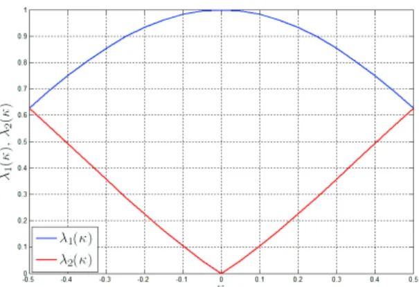
Fig. 4: λ1(κ) and λ2(κ) as a function of κ
where ⌊(.)⌋ stands for the integer part of (.). Then, after sampling att0+ mTs, we have the following expression:
y(t0+ mTs) = X k ak r(t0+ (m − k)Ts) + b(t0+ mTs) = am r(t0) + am−L r(t0+ LTs) + am−L−(κ |κ|)r(t0+ (L + ( κ |κ|))Te) + X k6=m k6=m−L k6=m−L−(κ |κ|) ak r(t0+ (m− k)Te) + b(t0+ mTs) (13)
Thanks to Nyquist filtering g(t) and neglecting the term with g(t0+ τGR) associated to the symbol am, the expression of
the sampled signal can be simplified as
y(t0+ mTs) = h1g(t0) am+ h2g(t0) λ1(κ) am−L + h2g(t0) λ2(κ) am−L−(κ |κ|) +h2 X k6=m k6=m−L k6=m−L−(κ |κ|) ak g(t0+ (m − k)Ts− τm) | {z } µk | {z } νκ(m) + b(t0+ mTs). (14)
The coefficientsλ1(κ) and λ2(κ) are given the following
expressions (see also Fig. 4): λ1(κ) = g(t0+ LTs− τGR) g(t0) = g(t0− κTs) g(t0) (15) λ2(κ) = g(t0+ (L + (|κ|κ))Ts− τGR) g(t0) = g(t0+ κ |κ|(1 − |κ|)Ts) g(t0) (16)
B. Simplified equivalent discrete channel model
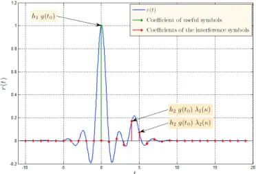
Fig. 5 represents the signalr(t) as given in equation (10). Coefficientsh2g(t0) λ1(κ) and h2g(t0) λ2(κ) are inside the
Fig. 5: Discrete equivalent channel filter,t0= 0, κ = 0.3.
Fig. 6: Discrete equivalent channel model with one term for residual interference
outside. Since almost 90% of the power of g(t − τGR) is on
its main lobe, we can neglect the coefficients outside. In other words, we can neglect νκ(m) in equation (14) to obtain
y(t0+ mTs) =
useful term
z }| { ˜ h1 am +
main interference term
z }| { ˜ h2am−L + g(t0)λ2(κ)h2am−L−(κ |κ|) | {z }
residual interference term
+ b(t0+ mTs),
where ˜h1= g(t0) λ1 h1 and ˜h2= g(t0) λ2 h2.
As shown in Fig. 6, the received signal samples ym =
y(t0+mTs) can thus be obtained from the emitted symbols am
using the convolution with a sparse two taps(˜h1, ˜h2) channel
of memory L + 1 and adding a residual interference term. This model is the simplest model that can be drawn from the equivalent discrete channel model. Of course, the model can be further refined by considering additional terms for the residual interference term leading to a more accurate model for the residual interference to be taken into account.
Fig. 7: Proposed MAP equalizer structure
IV. EFFICIENT CHANNEL EQUALIZATION FOR THE AERONAUTICAL CHANNEL
A. Existing equalization solutions for sparse channels Sparse channel equalization has been considered in several works [4]–[7] to exploit the sparsity, mainly using parallel trellis based detection algorithm such as Viterbi or MAP algorithms. For equalization of zero padded sparse channels, the parallel MAP receiver is shown to be optimal [5], [6], [8]. For more general sparse channels, interference cancellation has been taken into account by introducing inter-trellis interfer-ence mitigation between parallel trellis. This is done at the expense of additional complexity due to the need for proper scheduling [7], [9]. Several extensions of these works have been considered for application in turbo-equalization [6], [10], [11]. However, in these approaches, there is no consideration for a particular structure of the sparse channel. In our context, we try to take further benefit from the sparse nature of the channel by considering the relative power levels of the different channel taps to have an efficient interference cancellation scheme combined with parallel equalizers.
B. Proposed MAP equalizer structure
Knowing the values ˜h1 and ˜h2, the proposed equalizer
model as presented in Fig. 7 is composed of two blocks. The lower block presents the Feed-back; it is used to remove the residual interference term. The upper block is used to equalize the underlying sparse channel [7] [6] [8]. This block is able to equalize in parallelL streams of the received signal such that in each stream, a channel with two successive taps[˜h1, ˜h2] is
equalized.
The receiver contains three main steps. In the first step, the signal to be equalized is passed by the upper block com-posed of independent parallel Maximum A Posteriori (MAP) equalizers, which considers the incoming block symbols as the result of convolution with a sparse two taps channel assuming that fading coefficients ˜h1 and ˜h2 are known. Thus, we
intentionally consider a mismatched decoding by neglecting the effect of the residual interference. This is motivated by the power distribution properties of the considered channels. At the second step, the second block (Feed-back) estimates and generates the interference term taking into consideration
Ψ
5° 20° 40° 70°
[C/M ]dB 6 14 22.5 40
TABLE I: C/M as a function of Ψ
a decision of outgoing symbols of the first block. After generating the remaining interference, it is canceled from the incoming signal before feeding to the parallel equalizers. In the third step, the signal with reduced residual interference will be detected using the parallel MAP equalizers. The detection and interference cancellation steps are iteratively processed. Compared to existing solutions, we do not consider inter-ference cancellation between parallel trellis that leads to the definition of a particular scheduling during the detection step. We rather consider mismatched decoding while performing block based interference cancellation from detected symbols on the received signal.
In this paper, we have considered Maximum A Posteriori (MAP) equalizers. For each flow the complexity of the trellis it equal toM , where M is the modulation order. Thus the com-plexity scales linearly with L. In result, the total complexity of the proposed equalizer is equal to O (L × M). Compared to a conventional MAP equalizer with complexity ML+1, the
proposed equalizer structure has a reduced complexity, that is due to the parallel trellis structure inherited from the sparse component of the channel.
V. SIMULATION RESULTS
A. Simulation parameters
Practically, the parameters of the model can be computed for different elevation angles, aircraft speeds, aircraft heights, receiving antennas, carrier frequencies, always assuming a geostationary satellite. Based on [15] we will take a Rice factor of14dB ( [kLOS]dB= 10 log10(PD / PSCAT) ≈ 14dB ) for
the LOS path. The collected data was shown to be matching with the theoretical considerations in [13]. It is shown in [16] that the power ratio of the signal-to-multipath, denotedC/M , depends on the elevation angle Ψ as shown in Table I.
Assuming thatPD+ PSCAT+ PGR= 1 and Knowing the
value of C/M = (PD + PSCAT) / PGR we can deduct the
value of the power for the different paths as follows:
PGR= 1 / (1 + C/M )
PSCAT = (1 − PGR) / (1 + kLOS)
PD= kLOS PSCAT
B. Uncoded case performance
In Fig. 8, we present the performance in terms of BER (Bit Error Rate) for an uncoded BPSK (Binary Phase Shift Keying) modulation. Performance shown by the red curve represents the unequalized case. For the blue curve, we assume a simple parallel MAP equalizer (mismatched decoder). The curve in black represents the case where we add a feedback block to
Fig. 8: Uncoded BER BPSK, C/M = 6 dB
Fig. 9: Uncoded BER 8-PSK, C/M = 6 dB
iteratively mitigate the effects of residual interference using three iterations. It can be seen that we are achieving the perfect feedback case. In Fig. 9, for the case of an 8-PSK modulation, the same kinds of results are observed.
C. Coded case performance
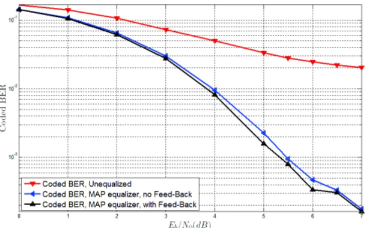
In Fig. 10, we consider a coded BPSK modulation using ARJA (Accumulate Repeat Jagged Accumulate) protograph based low-density parity-check (LDPC) codes of rateR = 2/3 with information length K = 2048 bits. We only consider serial channel equalization and channel decoding. The results show that we always have a significant gain when using an equalizer, however the performance when using a feedback block or not are almost identical. As a consequence, in order to have a low-complexity system it would be better to use an equalizer without a feedback block. The residual interference being low-powered, it does not have a visible effect on the performance of the coded BPSK modulation. This result is not valid for higher order modulations such as 8-PSK. In Fig. 11, for the 8PSK modulation, we notice the gain resulting from the contribution of an equalizer with a feedback block enabling interference cancellation.
Fig. 10: Coded BPSK, C/M = 6 dB
Fig. 11: Coded 8-PSK, C/M = 6 dB
VI. CONCLUSION
In this paper, we have investigated an efficient imple-mentation of channel equalization for aeronautical channels using a satellite link. The discrete equivalent channel can be decomposed in a strong sparse channel component with additional low power interference residual terms. Based on this model, an efficient equalizer structure can be derived that considers independent parallel MAP equalizers with proper it-erative interference cancellation. The proposed scheme exhibits interesting performance. Further investigations will consider turbo-equalization based on this structure.
ACKNOWLEDGMENTS
The authors would like to thank the Deutschen Zentrums für Luft- und Raumfahrt (DLR) for providing us their reference sofware for the simulation of the aeronautical channel.
This work has been partly supported by the French National Agency for Research (Agence Nationale pour la Recherche, ANR) under Grant Number ANR-13-SECU-0003 (CSOSG13 SURICATE project).
REFERENCES
[1] B. Gadat, E. L. E. Ho, H. Gonzalez, and F. Zeppenfeldt, “Satellite communications : a key enabler for UAV insertion into civil airspace,” Toulouse Space Show, 2012.
[2] E. Haas, “Aeronautical channel modeling,” IEEE Transactions on Ve-hicular Technology, vol. 51, no. 2, pp. 254–264, Mar. 2002. [3] A. Lehner and A. Steingass, “A Novel Channel Model for Land Mobile
Satellite Navigation,” Proceedings of the 18th International Technical Meeting of the Institute of Navigation Satellite Division, Long Beach, California, USA, pp. 2132–2138, 2005.
[4] N. Benvenuto and R. Marchesani, “The viterbi algorithm for sparse channels,” Communications, IEEE Transactions on, vol. 44, no. 3, pp. 287–289, Mar 1996.
[5] N. McGinty, R. Kennedy, and P. Hocher, “Parallel trellis viterbi algo-rithm for sparse channels,” Communications Letters, IEEE, vol. 2, no. 5, pp. 143–145, May 1998.
[6] F. H. Lee and P. Mclane, “Parallel-Trellis Turbo Equalizers for Sparse-Coded Transmission over SISO and MIMO Sparse Multipath Channels,” IEEE Transactions on Wireless Communications, vol. 5, no. 12, pp. 3568–3578, Dec. 2006.
[7] J. Mietzner, S. Badri-Hoeher, I. Land, and P. a. Hoeher, “Equalization of Sparse Intersymbol-Interference Channels Revisited,” EURASIP Jour-nal on Wireless Communications and Networking, vol. 2006, pp. 1–13, 2006.
[8] J. Mietzner, S. Badri-Hoeher, I. Land, and P. Hoeher, “Trellis-based equalization for sparse ISI channels revisited,” Proceedings. Interna-tional Symposium on Information Theory, 2005. ISIT 2005., pp. 229– 233, 2005.
[9] F. Lee and P. McLane, “Iterative parallel-trellis MAP equalizers with nonuniformly-spaced prefilters for sparse multipath channels,” Proceed-ings IEEE 56th Vehicular Technology Conference, vol. 4, pp. 2201– 2205, 2002.
[10] J. Park and S. Gelfand, “Turbo equalizations for sparse channels,” in Wireless Communications and Networking Conference, 2004. WCNC. 2004 IEEE, vol. 4, March 2004, pp. 2301–2306 Vol.4.
[11] ——, “Sparse map equalizers for turbo equalizations,” in Vehicular Technology Conference, 2005. VTC 2005-Spring. 2005 IEEE 61st, vol. 2, May 2005, pp. 762–766 Vol. 2.
[12] M. Richharia, N. Kaluvala, M. Alvarez-diaz, and A. Jahn, “Aeronautical Channel Model for Broadband L-Band,” pp. 1–12.
[13] P. Bello, “Aeronautical Channel Characterization,” IEEE Transactions on Communications, vol. 21, no. 5, pp. 548–563, May 1973. [14] A. Neul, J. Hagenauer, W. Papke, F. Dolainsky, and F. Edbauer,
“Propagation measurements for the aeronautical satellite channel,” in Vehicular Technology Conference, 1987. 37th IEEE, vol. 37, June 1987, pp. 90–97.
[15] A. Steingass, A. Lehner, F. Pérez-Fontàn, E. Kubista, and B. Arbesser-rastburg, “Characterization of the aeronautical satellite navigation chan-nel through high-resolution measurement and physical optics simula-tion,” Int. J. Satellite Communications Networking 26(1), no. October 2007, pp. 1–30, 2008.
[16] P. Spiga, G. Soriano, and M. Saillard, “Scattering of Electromagnetic Waves From Rough Surfaces: A Boundary Integral Method for Low-Grazing Angles,” IEEE Transactions on Antennas and Propagation, vol. 56, no. 7, pp. 2043–2050, Jul. 2008.